Table of Contents
Advertisement
Quick Links
ASM 456 interface module
SIMATIC Ident
RFID systems
ASM 456 interface module
Operating Instructions
07/2015
J31069-D0162-U001-A6-7618
___________________
Introduction
___________________
Description
___________________
Installation
___________________
Connection
___________________
Parameterization
___________________
Diagnostics
___________________
Firmware update
___________________
Technical specifications
___________________
Dimensional drawings
___________________
Appendix
1
2
3
4
5
6
7
8
9
A
Advertisement
Table of Contents

Related Manuals for Siemens ASM 456


Summary of Contents for Siemens ASM 456
- Page 1 ___________________ ASM 456 interface module Introduction ___________________ Description ___________________ SIMATIC Ident Installation ___________________ Connection RFID systems ASM 456 interface module ___________________ Parameterization ___________________ Diagnostics Operating Instructions ___________________ Firmware update ___________________ Technical specifications ___________________ Dimensional drawings ___________________ Appendix 07/2015 J31069-D0162-U001-A6-7618...
- Page 2 Note the following: WARNING Siemens products may only be used for the applications described in the catalog and in the relevant technical documentation. If products and components from other manufacturers are used, these must be recommended or approved by Siemens. Proper transport, storage, installation, assembly, commissioning, operation and maintenance are required to ensure that the products operate safely and without any problems.
-
Page 3: Table Of Contents
Wiring connection block ECOFAST ..................21 Wiring connection block M12, 7/8"..................25 Loop-through connection of PROFIBUS DP and supply voltage ........... 30 Connecting an ASM 456 up to functional earth ..............31 Parameterization ........................... 33 Hardware configuration ......................33 Parameter setting by means of GSD file ................35 Parameter assignment with FB 45/55 and FC 56 .............. - Page 4 Table of contents Appendix .............................. 57 Connecting cables ......................... 57 A.1.1 Routing of standard cables ....................57 A.1.2 Self-assembled cables ......................59 Ordering data ......................... 60 Service & Support ........................62 ASM 456 interface module Operating Instructions, 07/2015, J31069-D0162-U001-A6-7618...
-
Page 5: Introduction
Purpose of these operating instructions The information provided in these operating instructions will enable you to start up and operate the interface module ASM 456 on the PROFIBUS DP as a DP slave. Basic knowledge required These operating instructions assume general knowledge of automation engineering and identification systems. - Page 6 SIMATIC ®, SIMATIC RF ®, MOBY ®, RF MANAGER ® and SIMATIC Sensors ® are registered trademarks of Siemens AG. Guide These operating instructions describe the hardware of the interface module ASM 456. They comprise introductory chapters and reference chapters (e.g. technical data). The operating instructions include the following subject areas: ●...
-
Page 7: Description
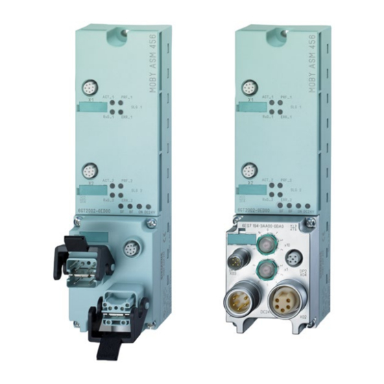
Description Area of application The ASM 456 interface modules are slave modules for the operation of RFID readers and code readers via PROFIBUS DP-V1 on any controllers. Figure 2-1 Interface module ASM 456 with ECOFAST or M12, 7/8" terminal block When operating the interface module with a SIMATIC S7, convenient function blocks are available to the user. - Page 8 PROFIBUS nodes (e.g. DI/DO) can still be processed at great speed. Up to 2 readers can be operated at the same time on the ASM 456. This allows you to start a command at the same time on 2 readers (using the corresponding FB/FC).
- Page 9 The ASM has a terminal block for connecting up to the PROFIBUS DP which is available as an option and the ECOFAST version or M12, 7/8". The following figure shows the basic design of the ASM 456. Figure 2-2 Basic design of the ASM 456...
- Page 10 Figure 2-4 Sample configuration ASM 456 The ASM 456 is linked into STEP 7 by means of a GSD file. The ASM can then be configured using HW Config of the SIMATIC Manager, the device configuration of the TIA Portal or another PROFIBUS tool (e.g. operating mode). You will find the GSD file on the DVD "RFID Systems, Software &...
-
Page 11: Installation
Installation Mounting position, mounting dimensions Mounting position There are no restrictions regarding the mounting position of the ASM 456. Mounting and clearance dimensions The following table shows the installation dimensions and clearance distances. Table 3- 1 Mounting dimensions Dimensions Mounting width... -
Page 12: Installing The I/O Module
3.2 Installing the I/O module Installing the I/O module Simple installation The ASM 456 is designed for easy mounting. Properties ● The I/O module should be mounted on a solid surface. ● The I/O module can be prewired (without installed terminal block). -
Page 13: Installing The Terminal Block
Installation 3.3 Installing the terminal block Installing the terminal block Properties The terminal block is used to connect the ASM 456 to PROFIBUS DP and supplies power to the device. Requirements The base unit is already mounted. Tools required Recessed head screwdriver, medium size Installing the terminal block 1. -
Page 14: Replacing Labels
1. Push the screwdriver into the small opening of the label at an angle, then lever it out. Figure 3-2 Removing labels 2. Push the label into the module using your fingers. ASM 456 interface module Operating Instructions, 07/2015, J31069-D0162-U001-A6-7618... -
Page 15: Removing The Asm 456
3.5 Removing the ASM 456 Removing the ASM 456 Procedure The ASM 456 is wired up and operational. Follow the steps below to remove the ASM: 1. Switch off the supply voltage for the ASM 456. 2. Disconnect the wiring from the terminal block. - Page 16 Installation 3.5 Removing the ASM 456 ASM 456 interface module Operating Instructions, 07/2015, J31069-D0162-U001-A6-7618...
-
Page 17: Connection
(https://support.industry.siemens.com/cs/ww/en/view/59193579)". Reader connector system One reader always occupies one M12 connector socket (X1, X2) on the ASM 456. A pre- assembled cable therefore permits the optimum and simple connection of the reader. The standard version connection cable is 2 m long. -
Page 18: Setting The Profibus Address
NOTICE Number of operable readers/reading points Note that you can normally connect two readers to the ASM 456 and operate them. The readers RF680R and RF685R are an exception. On the ASM 456, only one RF680R/RF685R reader can ever be operated at connector socket X1 and one reading point. - Page 19 – Upper rotary switch: 10th position 3. Screw the two seal caps back onto the rotary switches (torque: 0.5 to 0.8 Nm.) Figure 4-2 Setting PROFIBUS addresses on connection block M12, 7/8” ASM 456 interface module Operating Instructions, 07/2015, J31069-D0162-U001-A6-7618...
- Page 20 5. After starting up the first time, the connector can be removed again. The PROFIBUS address remains stored on the ASM 456. To ensure it remains watertight, the plug should be sealed with a screw cap.
-
Page 21: Wiring Connection Block Ecofast
ECOFAST connector plug. ● You can loop the supply voltages and PROFIBUS DP through via another ECOFAST connector plug. ● The first and last ASM 456 (consumer) on the PROFIBUS DP must be terminated with the terminating resistor. Requirements You have set the PROFIBUS address (according to your project). - Page 22 (wiring end for supply and loop-through connec- tion) PROFIBUS DP signal A PROFIBUS DP signal B Electronics/encoder supply (1L+) (voltage supply for ASM 456 and write/read device) Ground for electronic / encoder supply (1M) Load voltage ground (2M) Load voltage supply (2L+)
- Page 23 In so doing, note the mechanical coding of the connector plugs for supply and loop-through connection. 3. Press up the interlock for ECOFAST connector plugs. Figure 4-5 Connecting up ECOFAST connector plugs ASM 456 interface module Operating Instructions, 07/2015, J31069-D0162-U001-A6-7618...
- Page 24 (1L+) is within the tolerance range of 20 - 30 V. Sealing unused sockets Seal all unused ASM 456 sockets using caps in order to achieve degree of protection IP65, IP66 or IP67. For order numbers, refer to "Ordering data" section.
-
Page 25: Wiring Connection Block M12, 7/8
● You can loop the supply voltages and PROFIBUS DP through via M12 and/or 7/8” round sockets. ● On nodes (ASM 456) at the beginning or end of a PROFIBUS DP chain, a terminating resistor must be turned on. Requirements ●... - Page 26 Data line B (RxD / TxD-P) Shield Thread Shield *) Can only be used for the M12 terminating resistor. Looping the voltage through to the next connector via a 5-core cable is not permitted. ASM 456 interface module Operating Instructions, 07/2015, J31069-D0162-U001-A6-7618...
- Page 27 View of 7/8” connector (wiring side) Chassis load voltage supply (2M) Chassis electronics/sensor supply (1M) Electronics / encoder supply (1L+) (voltage supply for ASM 456 and write/read device) Load voltage supply (2L+) (unused on ASM 456) Note When connecting up the supply voltage, we recommend the cable specified in the "Ordering data"...
- Page 28 1. Press the connector (M12 or 7/8”) into the relevant round socket on the connection block. Make sure the connectors and sockets are properly interlocked (tongue and groove). 2. Use the knurled locking ring to secure the connector. Figure 4-7 Connecting M12, 7/8" connectors ASM 456 interface module Operating Instructions, 07/2015, J31069-D0162-U001-A6-7618...
- Page 29 If the ASM 456 is the last PROFIBUS node, then you must terminate PROFIBUS DP with the M12 terminating resistor. For the order number, refer to the section "Ordering data".
-
Page 30: Loop-Through Connection Of Profibus Dp And Supply Voltage
Loop-through connection of PROFIBUS DP and supply voltage NOTICE Ensuring the degree of protection The IP65, IP66 or IP67 degree of protection is no longer guaranteed if the terminal block is removed. ASM 456 interface module Operating Instructions, 07/2015, J31069-D0162-U001-A6-7618... -
Page 31: Connecting An Asm 456 Up To Functional Earth
Connecting an ASM 456 up to functional earth Properties The ASM 456 needs to be connected to functional earth. This normally happens automatically when you mount the device on a grounded metal support. If you mount the module on a support that is not grounded, a separate grounding screw must be provided on the communications bus. - Page 32 Connection 4.5 Connecting an ASM 456 up to functional earth Required accessories (optional) ● M5 x 10 retaining bolt and washers ● Grounding cable (copper braided cable) with minimum cross-section of 4 mm ● Cable lug Connecting the ASM 456 to functional earth...
-
Page 33: Parameterization
Parameterization Hardware configuration The ASM 456 is integrated into the hardware configuration of the SIMATIC Manager, the TIA Portal or other configuration software using the GSD file "SIEM8114.GSD". The file is incorporated into HW Config of the SIMATIC Manager using the "Options > Install new GSD ..."... - Page 34 To allow the configuration software to use the full functionality (diagnostics texts, firmware update), support of GSD revision 5 or higher is required. The ASM 456 is displayed in the device configuration under "Other field devices > PROFIBUS DP > Ident Systems > SIEMENS AG > MOBY".
-
Page 35: Parameter Setting By Means Of Gsd File
In addition to the PROFIBUS-relevant control parameters, several MOBY-relevant control parameters are also defined for the ASM 456 in the GSD file. The relevant parameters are set using the "Object properties" of the slave in HW Config or the TIA Portal. The parameters are described in the function manual "FB 45"... -
Page 36: Parameter Assignment With Fb 45/55 And Fc 56
MOBY D: B#16#00, 01 You will find special information on the input parameters for ASM 456 with FB45 in combination with the RF620R/RF630R readers in the section "Parameterizing > Parameterizing RF620R/RF630R with FB 45 > Input parameters" in the "Configuration Manual RF620R/RF630R". - Page 37 Parameterization 5.3 Parameter assignment with FB 45/55 and FC 56 Input parameters for ASM 456 with FC 56 The assignment is made in UDT 10. Table 5- 3 Input parameters for ASM 456 with FC 56 Address Name Permissible values Comment +0.0...
-
Page 38: Table Of Commands For Asm 456
5.3 Parameter assignment with FB 45/55 and FC 56 5.3.2 Table of commands for ASM 456 Table of commands of the ASM 456 with standard addressing (FB 45) The assignment is made in UDT 20/UDT 30 using the "command" variable. Table 5- 4... - Page 39 Parameterization 5.3 Parameter assignment with FB 45/55 and FC 56 ASM 456 instruction table for filehandler addressing (FC 56) The assignment is made in UDT 50 using the "command" variable. Table 5- 5 ASM 456 commands with filehandler addressing Command...
-
Page 40: Parameter Assignment With The Ident Profile And Fb 101/116/132
Note that the input parameters of the RFID standard profile differ from those of the Ident profile essentially due to the changed physical address setting of the reader. Figure 5-3 Input parameters for ASM 456 with the Ident profile and RFID standard profile with FB 101/116/132 ASM 456 interface module Operating Instructions, 07/2015, J31069-D0162-U001-A6-7618... -
Page 41: Table Of Commands For Asm 456
5.4.2 Table of commands for ASM 456 Table of commands of the ASM 456 with Ident profile/RFID standard profile (FB 101/116/132) Assignment is made in UDT 1 using the "command" variable. Note that some of the commands shown in the table are block-specific and cannot be used with both blocks. - Page 42 5.4 Parameter assignment with the Ident profile and FB 101/116/132 Command Command code Description ASCII READ-CONFIG Reads out the parameters from the communications mod- ule/reader. WRITE-CONFIG Sends new parameters to the communications module/reader. ASM 456 interface module Operating Instructions, 07/2015, J31069-D0162-U001-A6-7618...
-
Page 43: Diagnostics
Diagnostics Diagnosis using LEDs The following figure shows details of the LEDs of the ASM 456. Figure 6-1 LEDs of the ASM 456 Table 6- 1 Status LEDs for ASM 456 LEDs Meaning Lights up when there is logic voltage at the ASM (is generated by the 24 V sup- ply voltage). - Page 44 • The set PROFIBUS address is Set the address in the range 1 to 99 • • incorrect or greater than 99. and carry out new run-up. – = Status not relevant ASM 456 interface module Operating Instructions, 07/2015, J31069-D0162-U001-A6-7618...
-
Page 45: Parameterization Of The Diagnostics
– = not relevant Parameterization of the diagnostics In addition to the PROFIBUS standard diagnostics, the ASM 456 offers user-specific diagnostics data structured in the form of device-related diagnostics. Along with error messages that are also communicated with command processing, diagnostics data contain cross-application information such as the start of a firmware update. - Page 46 The event is no longer current, a diagnostics message is output without a set Ext_Diag bit. For events that only exist momentarily, the reset is delayed by 3 seconds. The hard errors are supported by text messages stored in the GSD file. ASM 456 interface module Operating Instructions, 07/2015, J31069-D0162-U001-A6-7618...
-
Page 47: Structure Of The Diagnostics Frame
The diagnostics frame consists of 6 bytes of standard diagnostics and 18 bytes of diagnostics extension. For the ASM 456, the diagnostics extension is designed as a status PDU for device-related diagnostics. The structure complies with the PROFIBUS Profile Guideline (PROFIBUS Proxy Guideline, Identification Systems Proxy Ident Function Block) for Identification Systems with MOBY-specific additional information. - Page 48 Diagnostics 6.3 Structure of the diagnostics frame ASM 456 interface module Operating Instructions, 07/2015, J31069-D0162-U001-A6-7618...
-
Page 49: Firmware Update
Firmware update The firmware of the ASM 456 can be updated via PROFIBUS. You have several options for updating the firmware: ● With STEP 7 Classic ● With STEP 7 Basic / Professional (TIA Portal) Note Firmware update with connected RF680R/RF685R readers Note that when the RF680R/RF685R are connected to the ASM 456, the firmware update of the readers must be performed via the WBM of the readers. - Page 50 (see section Diagnostics (Page 43)). Firmware update with the TIA Portal (STEP 7 Basic / Professional) Follow the steps below to run a firmware update on the ASM 456 with the TIA Portal: 1. Start the TIA Portal in the project view.
- Page 51 – If this option is selected, a successful update is followed by a new startup of the ASM (active commands on the ASM are canceled). – If the option is not selected, the ASM 456 continues to operate with the previous firmware version. The new firmware is activated the next time the power supply is cycled.
- Page 52 Firmware update ASM 456 interface module Operating Instructions, 07/2015, J31069-D0162-U001-A6-7618...
-
Page 53: Technical Specifications
Technical specifications 6GT2002-0ED00 Product type designation ASM 456 Technical specifications - interfaces ASM 456 (normal addressing) ASM 456 (filehandler) Serial interface to the user Principle PROFIBUS DP-V1 Transmission rate 9600 Bd to 12 MBd (automatic detection) Plug-in connection EN 50170 Vol. 2 PROFIBUS M12, 7/8"... - Page 54 (File E116536) • To allow this, the relevant profile block is required on the non-Siemens system; according to the PIB specification of PROFIBUS INTERNATIONAL to IEC 611313; order no. of the specification: 3.142 All supply and signal voltages must be safety extra-low voltage (SELV/PELV according to EN 60950) 24 VDC supply: Safety (electrical) isolation of low voltage (SELV / PELV acc.
-
Page 55: Dimensional Drawings
Dimensional drawings The following figure shows the dimensional drawing of an ASM 456 with bus connection block. Figure 9-1 Dimensional drawing of ASM 456 (in mm) ASM 456 interface module Operating Instructions, 07/2015, J31069-D0162-U001-A6-7618... - Page 56 Dimensional drawings ASM 456 interface module Operating Instructions, 07/2015, J31069-D0162-U001-A6-7618...
-
Page 57: Appendix
● Extension cable for all RFID / MOBY systems ● Length: 2 m, 5 m, 10 m, 20 m, 50 m Figure A-3 Connecting cable M12 ↔ D-sub ● Connecting cable MOBY D ● Length: 2 m ASM 456 interface module Operating Instructions, 07/2015, J31069-D0162-U001-A6-7618... - Page 58 A.1 Connecting cables Maximum cable length The ASM 456 can be operated with every reader configuration with the maximum cable length of 50 m. In some situations, longer connecting cables up to 1000 m are possible. The current consumption of the connected reader must, however, be taken into account. You will find information in the relevant system manuals.
-
Page 59: Self-Assembled Cables
MOBY catalog. The pin assignment is listed in the following table. Cable structure You will need cables of the following specifications for self-assembled cables: 7 x 0.25 mm LiYC11Y 7 x 0.25 ASM 456 interface module Operating Instructions, 07/2015, J31069-D0162-U001-A6-7618... -
Page 60: Ordering Data
−RxD manufacturer −TxD Free PE / shield Ordering data Table A- 5 Ordering data - ASM 456 Article number ASM 456 communications module 6GT2002-0ED00 for PROFIBUS DP V1 max. 2 readers can be connected ECOFAST terminal block 6ES7194-3AA00-0AA0 M12, 7/8" terminal block... - Page 61 DVD "RFID Systems Software & Documentation" 6GT2080-2AA20 with FB 45/55, FC 56, FB 101/116/132, Ident profile, GSD/GSDML files, driv- ers, tools and RFID documentation Not permitted in conjunction with the RF680R/RF685R readers ASM 456 interface module Operating Instructions, 07/2015, J31069-D0162-U001-A6-7618...
-
Page 62: Service & Support
● In the catalog ID 10 specially for Industrial Identification Systems Service & Support for Process Industries and Drives On the Internet, on the Support home page (https://support.industry.siemens.com/cs/de/en/) of Process Industries and Drives (PD), you will find various services. There you will find the following information, for example: ●... - Page 63 D-90327 Nuremberg. Phone: +49 (0) 180 523 56 11 (€ 0.14 /min. from the German landline network, deviating mobile communications prices are possible) For information about courses, see the SITRAIN homepage (http://sitrain.automation.siemens.com/sitrainworld/). ASM 456 interface module Operating Instructions, 07/2015, J31069-D0162-U001-A6-7618...
- Page 64 Appendix A.3 Service & Support ASM 456 interface module Operating Instructions, 07/2015, J31069-D0162-U001-A6-7618...