Table of Contents
Advertisement
Quick Links
Download this manual
See also:
User Manual
Advertisement
Table of Contents

Related Manuals for Advantech DS-570


Summary of Contents for Advantech DS-570
- Page 1 User Manual DS-570 Graphics-Enhanced Digital Signage Player Powered by NVIDIA GeForce GT730M...
- Page 2 The documentation and the software included with this product are copyrighted 2014 by Advantech Co., Ltd. All rights are reserved. Advantech Co., Ltd. also reserves the right to improve the products described in this manual at any time without notice. No part of this manual may be reproduced, copied, translated, or transmitted in any form or by any means without the prior written permission of Advantech Co., Ltd.
- Page 3 Product Warranty (1 year) Advantech warrants the original purchaser that each of its products will be free from defects in materials and workmanship for two years from the date of purchase. This warranty does not apply to any products that have been repaired or altered by persons other than repair personnel authorized by Advantech, or products that have been subject to misuse, abuse, accident, or improper installation.
- Page 4 Technical Support and Assistance Visit the Advantech website at http:// .com for the latest prod information. Contact your distributor, sales representative, or Advantech's customer service center for technical support if you require additional assistance. Please have the following information ready before calling: –...
-
Page 5: Packing List
Packing List Before installation, please ensure that the following items have been shipped: 1 x DS-570 unit 1 x accessory box containing the items listed below – 1 x power adapter bracket set –... -
Page 6: Safety Instructions
The sound pressure at the operator position does not exceed 70 dB (A), as per IEC 704-1:1982. DISCLAIMER: These instructions are provided according to IEC 704-1. Advantech disclaims all responsibility for the accuracy of all statements contained herein. DS-570 User Manual... -
Page 7: Table Of Contents
1.2.2 Display ..................2 1.2.3 Power Consumption..............2 Hardware Specifications ................3 Mechanical Specifications................. 4 Figure 1.1 DS-570 mechanical dimensions ......... 4 Power Requirements................. 4 Environmental Specifications ..............4 Chapter Hardware Installation ......5 DS-570 Front and Rear Views ..............6 Figure 2.1 Front view .............. - Page 8 Boot BIOS Feature Setup ............28 Figure 3.12Boot Configuration setup screen ......28 3.2.6 Save & Exit BIOS Feature Setup..........29 Figure 3.13Save & Exit Configuration setup screen....29 Chapter Software..........31 Intel® TXE Driver Installation..............32 DS-570 User Manual viii...
-
Page 9: Chapter 1 General Introduction
Chapter General Introduction This chapter gives background information regarding the DS-570 series. -
Page 10: Introduction
DS-570 features four display output interfaces (2 x HDMI, 1 x DP++, and 1 x VGA) to accommodate up to four simultaneous display outputs. For superior connectivity, DS- 570 supports two mini PCIe interfaces with add-on functions such as wireless net- works and TV tuner cards to fulfill various requirements. -
Page 11: Hardware Specifications
HDD: Supports 1 x 2.5" SATA HDD (7 mm height only) SSD: Shared with the 2.5" SATA HDD bay (7 mm height only) Watchdog Timer: Supported by Advantech SUSI API I/O Interface: 2 x RS-232 USB: 1 x USB 3.0 and 3 x USB 2.0-compliant ports ... -
Page 12: Mechanical Specifications
Dimensions: 220.0 x 150.0 x 44.2 mm (8.67" x 5.91" x 1.74") (L x W x H) 247.40 [9.740] 235.40 [9.268] 220 [8.661] Figure 1.1 DS-570 mechanical dimensions Weight: 1.7 kg (3.75 lb) Power Requirements System Power: –... -
Page 13: Chapter 2 Hardware Installation
Chapter Hardware Installation This chapter describes the DS-570 hardware installation process and external I/O. -
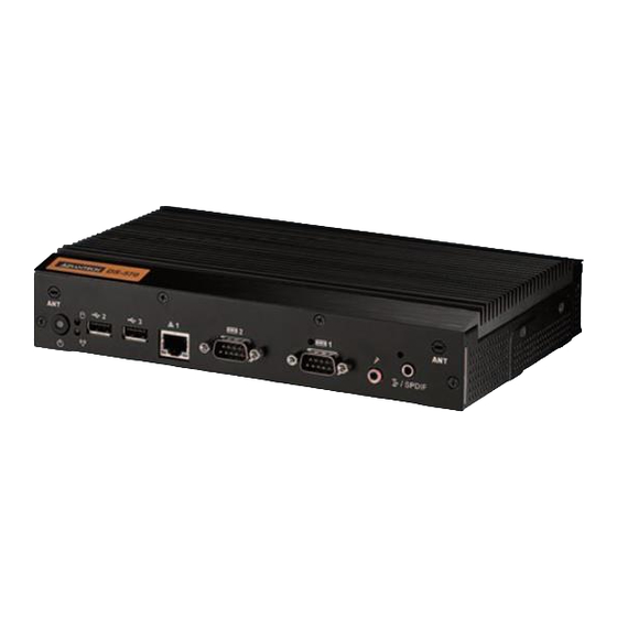
Page 14: Ds-570 Front And Rear Views
2.2.1 Power ON/OFF Button DS-570 features a power ON/OFF button on the front of the device. Push this button to turn the system on or off. DS-570 also supports the 4-second delay soft power off function. Figure 2.3 Power button 2.2.2... -
Page 15: Ethernet Connector (Lan)
2.2.3 Ethernet Connector (LAN) DS-570 provides two RJ45 LAN interface connectors (1 x LAN at the front and 1 x LAN at the rear) that are fully compliant with IEEE 802.3u 10/100/1000 Base-T CSMA/CD standards. The Ethernet port at the front supports a standard RJ-45 jack connector with LED indicators for denoting its active/link and speed status. -
Page 16: Com Connector
The S/PDIF port allows users to send digital audio to an amplifier or television, and also supports jack sensing and line-out function. Figure 2.8 S/PDIF connector DS-570 Rear External I/O Connectors 2.3.1 Power Input Connector DS-570 is equipped with a DC jack header that supports 19 V DC power input. DS-570 User Manual... -
Page 17: Vga Connector
Figure 2.9 DC input connector 2.3.2 VGA Connector DS-570 features one high-resolution VGA interface connected by a D-sub 15-pin connector to support VGA CRT-compatible monitors. The connector provides display resolutions of up to 2048 x 1536 @ 60 Hz. Figure 2.10 VGA connector Table 2.4: VGA Connector Pin Assignments... -
Page 18: Figure 2.11Hdmi Connector
Figure 2.11 HDMI connector Table 2.5: HDMI Connector Pin Assignments Signal Name TMDS Data2+ TMDS Data2– TMDS Data1+ TMDS Data1– TMDS Data0+ TMDS Data0– TMDS Clock+ TMDS Clock– +5 V Power Detect DS-570 User Manual... -
Page 19: Dp++ Connector
2.3.4 DP++ Connector The DS-570 DP++ connector not only supports DP output, but can also directly out- put single-link HDMI and DVI signals using a simple passive adapter. Although a maximum resolution of 3840 x 2160p is supported, the actual display resolutions depend on the monitor used. -
Page 20: Usb Connectors
2.3.5 USB Connectors On the rear of the DS-570 device are two USB interface connectors (1 x USB 2.0 and 1 x USB 3.0) that provide complete plug-and-play and hot-swapping capabilities for up to 127 external devices. The three USB 2.0 interfaces are compliant with USB UHCI specification, Rev. -
Page 21: Hardware Installation
Remove the heatsink by loosening the four fixing screws on the front and rear panels, as well as the two fixing screws inside the chassis. Insert the memory module into the memory socket. Perform the above steps in reverse to reassemble the system. Figure 2.14 Memory module installation DS-570 User Manual... -
Page 22: Hdd Installation
HDD Installation Attach the 2.5-inch SATA HDD to the HDD bracket by tightening the four fixing screws. Insert the HDD module into the system. Reassemble the HDD cover by tightening the two fixing screws. Figure 2.15 HDD installation DS-570 User Manual... -
Page 23: Mini Pcle And Sim Card Installation
Reattach the mini PCIe slot cover by tightening the fixing screws. Note 1 Mini PCIe 1 supports mSATA and mini PCIe cards. Note 2 The SIM card slot is located under the mini PCIe 2 slot. Figure 2.16 Mini PCIe and SIM card installation DS-570 User Manual... -
Page 24: Wireless Lan Antenna Installation
O panels, as well as the two fixing screws inside the chassis. Then loosen the four fixing screws on the front panel to remove the front cover. Attach the antenna onto the front I/O panel. Reassemble the system. Figure 2.17 Wireless LAN antenna installation DS-570 User Manual... -
Page 25: Bios Settings
Chapter BIOS Settings This chapter explains the BIOS configuration process. -
Page 26: Bios Introduction
BIOS Introduction With the AMI BIOS Setup program, users can modify the BIOS settings and control various system features. This chapter describes the basic navigation of the DS-570 series BIOS setup screens. AMI BIOS’s ROM features a built-in setup program that allows users to modify the basic system configuration. -
Page 27: Advanced Bios Features Setup
3.2.2 Advanced BIOS Features Setup Select the Advanced tab in the DS-570 BIOS Setup Utility to enter the Advanced BIOS setup screen. Highlight any items in the left frame, such as CPU configuration, and press <Enter> to access the submenu for that item. Users can view the Advanced BIOS Setup options for any item by highlighting the item using the <Arrow>... -
Page 28: Figure 3.3 Acpi Setup Screen
The ISCT sleep duration value is presented in seconds; the standard time format is not supported – ISCT RF Kill Switch Type Software/hardware ISCR RF kill switch type – ISCT RTC Timer Support Enable/disable the ISCT RTC timer ITE8528E Super I/O Configuration System Super I/O chip parameters DS-570 User Manual... -
Page 29: Figure 3.4 Hw Monitoring Screen
ITE8528E HW Monitor Monitor hardware status (PC health status) Figure 3.4 HW monitoring screen S5 RTC Wake Settings Enable/disable system wake from S5 using RTC alarm Figure 3.5 S5 RTC wake setup screen DS-570 User Manual... -
Page 30: Figure 3.6 Cpu Configuration Setup Screen
Serial Port Console Redirection Enable/disable Serial Port Console redirection CPU Configuration Allows users to adjust the CPU configuration Figure 3.6 CPU configuration setup screen PPM Configuration Enable/disable CPU C state report to OS DS-570 User Manual... -
Page 31: Figure 3.7 Ide Configuration Setup Screen
High Precision Timer Enable/disable the high precision event timer – PCI Express Dynamic Clock Gating Enable/disable PCIe dynamic clock gating – OS Selection Allows users to select the OS. The selected OS should be specified and employed. DS-570 User Manual... -
Page 32: Figure 3.8 Miscellaneous Configuration Setup Screen
Allows users to specify the USB mass storage device Start Unit Command timeout value. The value options available are 10, 20, 30, and 40 seconds. – Device Power-Up Delay Allows auto/manual configuration of the USB mass storage device Start Unit Command timeout value. DS-570 User Manual... -
Page 33: Figure 3.9 Usb Configuration Setup Screen
Figure 3.9 USB Configuration setup screen Security Configuration Intel® Anti-Theft Technology configuration Figure 3.10 Intel® TXE Configuration setup screen DS-570 User Manual... -
Page 34: Chipset Bios Feature Setup
3.2.3 Chipset BIOS Feature Setup Select the Chipset tab in the DS-570 BIOS Setup Utility to enter the Chipset BIOS setup screen. Users can select any item displayed in the left frame. North Bridge North Bridge parameters – Memory Information Max TOLUD: Maximum value of TOLUD ... -
Page 35: Security Bios Feature Setup
3.2.4 Security BIOS Feature Setup Select the Security tab in the DS-570 BIOS Setup Utility to enter the Security BIOS setup screen. Figure 3.11 Security Configuration setup screen Administrator Password Allows users to set the administrator password User Password... -
Page 36: Boot Bios Feature Setup
3.2.5 Boot BIOS Feature Setup Select the Boot tab in the DS-570 BIOS Setup Utility to enter the Boot BIOS setup screen. Users can select any item displayed in the left frame. Figure 3.12 Boot Configuration setup screen Setup Prompt Timeout Allows users to specify the number of seconds to wait for a setup activation key. -
Page 37: Save & Exit Bios Feature Setup
3.2.6 Save & Exit BIOS Feature Setup Select the Save & Exit tab in DS-570 BIOS Setup Utility to enter the Save & Exit BIOS setup screen. Figure 3.13 Save & Exit Configuration setup screen Save Changes and Exit Exit system setup after saving changes ... - Page 38 Allows users to launch the EFI Shell application (Shell.efi) from an available file system device – Reset System With ME Disable Mode MEUD000 ME will execute the temporary disable mode, or ignore if ME ignition is FWMED001 DS-570 User Manual...
-
Page 39: Software
Chapter Software This chapter explains the OS installation prompts. -
Page 40: Intel® Txe Driver Installation
Intel® TXE FW 1.1.0.1089 is possible; however, a downgrade from Intel® TXE FW 1.1.0.1113 to an earlier kit is not possible. Caution! Before OS installation, the selected OS should be specified and match the OS employed by the BIOS (refer to Figure 3.8). DS-570 User Manual... - Page 41 DS-570 User Manual...
Need help?
Do you have a question about the DS-570 and is the answer not in the manual?
Questions and answers