Table of Contents
Advertisement
Gas Metal Arc
Welding Machine
Welding Machine
USER MANUAL
USER MANUAL
Welding Method and Specifications
GMAW (MIG/MAG)
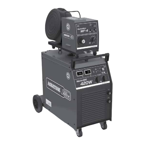
Eczacıbaşı - Lincoln Electric recommend to use "ASKAYNAK" gas metal arc
welding wire for obtaining high performance from MasterMIG 420W.
3
Phase
2 years limited spare part warranty
(Clamps and cables excluded)
Advertisement
Table of Contents

Subscribe to Our Youtube Channel
Related Manuals for ASKAYNAK MASTERMIG 420W


Summary of Contents for ASKAYNAK MASTERMIG 420W
- Page 1 USER MANUAL USER MANUAL Welding Method and Specifications Phase GMAW (MIG/MAG) 2 years limited spare part warranty (Clamps and cables excluded) Eczacıbaşı - Lincoln Electric recommend to use “ASKAYNAK” gas metal arc welding wire for obtaining high performance from MasterMIG 420W.
- Page 2 и свидетельствует о том, что aşağıda modeli belirtilen kaynak makinesinin declares that the welding machine déclare que le poste de soudage нижеуказанная модель сварочного аппарата ASKAYNAK MasterMIG 420W ® ® aşağıda belirtilen yönergelere uygun olduğunu conforms to the following directives est conformé...
-
Page 3: Table Of Contents
TOSB Otomotiv Yan Sanayi İhtisas Organize Sanayi Bölgesi 2. Cadde, No: 5, Şekerpınar 41420 Çayırova, KOCAELİ - TURKEY Tel: (+90 262) 679 78 00 Fax: (+90 262) 679 77 00 www.askaynak.com.tr Manufactured in People’s Republic of China by KAYNAK TEKNİĞİ SANAYİ ve TİCARET A.Ş. -
Page 4: Safety In Welding
Safety in Welding - 1 This Machines has been designed for GMAW (MIG/MAG). Shall not be used for any other purpose. Be sure that this machine should only operated by qualified personnel. Be sure that all installation, operation, maintenance and repair procedures are performed only by authorized personnel. - Page 5 Safety in Welding - 2 Other protective clothing used in dangerous situations are stated below: • Flame resistant clothing, • Gaiters, • Aprons, • Leather cuff gloves and capes, • Helmet used under the welding mask. To protect hands against burns, cuts and scratches, gloves made from flame resistant materials such as leather must be used.
- Page 6 Safety in Welding - 3 Primary electric shock is very dangerous since it is much higher than welding voltage. When the power to the machine is open, you can encounter with primary electric shock while your body is in contact with ground or touching a live point within the machine.
- Page 7 Safety in Welding - 4 GASES and FUMES CAN BE DANGEREOUS : When welding with electrodes which require special ventilation such as stainless or hard facing or on lead or cadmium plated steel and other metals or coatings which produce highly toxic fumes, keep exposure as low as possible and keep the exposure level under “Minimum Limit Values”...
- Page 8 Safety in Welding - 5 operation can easily go through small cracks and openings to adjacent areas. Until ensuring that precautions are used to fully clean flammable and toxic gases, never weld any tanks, drums, containers or material. Never operate welder in places that flammable gases, vapors or liquid fuels exist. Always keep in mind the fire risk due to high temperatures in arc welding.
- Page 9 Safety in Welding - 6 CYLINDER MAY EXPLODE IF DAMAGED : Use only compressed gas cylinders containing the correct shielding gas for the process used and properly operating regulators designed for the gas and pressure used. All hoses, fittings, etc. should be suitable for the welding application and maintained in good condition with a proper installation.
- Page 10 Safety in Welding - 7 WELDED HOT MATERIAL MAY CAUSE BURNS : High amounts of heat may be produced from welding process. Hot surfaces and material may cause serious burns. While touching or moving this kind of material, always wear gloves. ELECTRIC and MAGNETIC FIELDS MAY BE HAZARDOUS ON HUMAN HEALTH : Electric current flowing through any conductor causes electromagnetic fields.
-
Page 11: Safety In Welding
INFORMATION ON RESIDUAL RISKS: Askaynak MasterMIG 420W welder has been designed and manufactured in compliance with safety rules required by TS EN 60974-1 standard. To eliminate the safety risks all necessary precautions have been taken, precautions that need to be taken by operators and users and all rules to be followed have been stated in the user manual. -
Page 12: Electromagnetic Compliance
Electromagnetic Compliance - 1 Designed according to TS EN 60974-1. EMU Class of machine according to TS EN 55011 is Group 2 Class A. For detailed information refer to TS EN 60974-10. • While welding do not turn on/off the power switch. This situation may cause voltage fluctuations in mains as well as shorten the economic life of the machine. - Page 13 Electromagnetic Compliance - 2 building and other activities that are taking place. The surrounding area may extend beyond the boundaries of the premises. Assessment of welding installation In addition to the assessment of the area, the assessment of arc welding installations may be used to evaluate and resolve cases of interference.
-
Page 14: General Information
General Information - 1 Warning! Read entire section before installing and starting the machine. • Do not install, operate or repair the welder without reading safety precautions included in user manual. Keep this user manual and place to an easy accessible place. •... -
Page 15: General Information
General Information - 2 • Do not place the machine on a surface with a slope over 15° and do not operate on such surface. • Machine should always be operated in an environment having clean airflow and there should be no obstacle that prevents ventilation or stops airflow. Do not cover the machine while operating with paper, cloth or similar objects. -
Page 16: Specifications
Specifications - 1 • MasterMIG 420W, is a compact type gas metal arc (MIG/MAG) welding machine with combined wire feeder unit and power unit. • Especially suitable for spot welding and high quality welding of mild structural steels and stainless steels with medium thickness used in metal manufacturing industry. - Page 17 Specifications - 2 Input Input Voltage Power Consumption Frequency 380 V ± 10 / 3 Phase 21 kVA (25% operation cycle) 50/60 Hertz (Hz) Current Taken Output (min.) Power Factor (Cos ) (min.) From Mains 73 % 0.94 32.0 A (25 %) Welding Current Output Rates Duty Cycle Output Current...
-
Page 18: Preparations For Work
Preparation for Work - 1 Welding wire reel protection cabinet cover Wire feeder unit handle 2/4 trigger selection switch Gas flow without welding Wire feed control without control switch welding button Torch connector (EURO) Wire feed speed setting button Wheels Water pump switch Power indicator Digital welding... - Page 19 Preparation for Work - 2 Wire feeder unit handle Welding wire reel protection cabinet Shielding gas inlet socket Pin for placing wire Control cable connection socket feeder unit to power unit Coolant inlet and outlet sockets Wire feeder unit (+) power connection socket Wire feeder unit rear wheels...
- Page 20 Preparation for Work - 3 CONTROLS IN WIRE FEEDER UNIT...
- Page 21 Preparation for Work - 4 CONNECTION DIAGRAM...
-
Page 22: Installation And Operation
Installation and Operation - 1 Mains Supply • Mains supply connection of the machine should be made as per rules and only by qualified personnel trained with necessary information. • Welding machine has been designed for triphase mains supply, 380 V± 10, 50/60% and should be protected by 40A delay action fuse. - Page 23 Installation and Operation - 2 • Welding current circuit made by the connection of “Wire Feeder Unit Power Connection Sockets” located in the rear of power unit and wire feeder unit, to each other via “Wire Feeder Unit Connection Cable”. •...
- Page 24 Installation and Operation - 3 Welding Setting Button” located within the wire feeder unit. - Release “Wire Feed Without Welding Control Button” after the welding wire is seen and install the contact nozzle and gas nozzle to the welding torch and tighten properly. Adjusting Press Force of Wire Drive Reel - Properly set the press force of reels.
-
Page 25: Functions Of Wire Feeder System
Functions of Wire Feeder Unit Wire drive system has the following functions : Welding Torch Operation Modes : • 2 Trigger Mode (manual): Welding procedure is started by pressing and holding down the trigger on the welding torch. When trigger released welding stops. •... -
Page 26: Environment Conditions
Environment Conditions Warning ! Before starting the machine following procedures should be performed : • Provide the necessary environment conditions for the welding machine. For example there shouldn’t be any flammable gases and vapors, conducting dusts, burner/flammable fumes and other factors that may be hazardous for insulation and mechanical structure of the machine. -
Page 27: Gmaw (Mig/Mag) Method
GMAW (MIG/MAG) Method • Make sure that the welding machine is installed according to the explanations included on Page 68-70. • By considering the desired welding current values, install the work cable to the “Work Cable Connector” located in front of the welding machine by using the fitting screw at the end of work cable. -
Page 28: Efficient Use Of Machine In Terms Of Energy Consumption
Unpacking ASKAYNAK MasterMIG 420W Gas Metal Arc Welding Machine sold in its original cartoon box and on a pallet. Do not purchase the machines without packaging. To unpack the machine, cut the strap connected to the pallet and lift up the box. -
Page 29: Maintenance And Troubleshooting
Maintenance and Troubleshooting - 1 Warning ! Proper usage and performing periodical maintenance fully will enable high performance and important for long economical life. Maintenance, repair and service works should only performed by the qualified personnel who had the required training! Mains current of the welding machine should be disconnected and power cable should be unplugged while performing maintenance and service. - Page 30 Maintenance and Troubleshooting - 2 YEARLY MAINTENANCE Contact to authorized service for yearly maintenance. Grounding continuity and insulations test must be applied during yearly maintenance. Check if this tests has been done from the yearly maintenance report. SOLUTION REASON PROBLEM Spiral is dirty.
- Page 31 Maintenance and Troubleshooting - 3 REASON SOLUTION PROBLEM Supply voltage value is too Check the supply voltage as to be low (under 350 V). 380 ±10%V. One of the phases is missing Open circuit voltage is low. Check the mains phases. in supply voltage.
- Page 32 Maintenance and Troubleshooting - 4 REASON SOLUTION PROBLEM Gas hose is not connected Check the hose and gas connection or there is disconnection in system. Tighten the connections. the hose. Replace the hose if necessary. There is no shielding Gas hose is crushed or gas flow.
-
Page 33: Failures In Welding Seams
Failures in Welding Seams - 1 Pore Creation Possible Reasons : 1- Insufficient gas shielding. 2- Used gas is dirty or gas flow speed is not suitable. 3- Surface of welding wire is dirty. 4- Work piece is dirty. 5- Voltage value is too high. 6- Distance between the nozzle and workpiece (free wire length) is too much. - Page 34 Failures in Welding Seams - 2 Insufficient Penetration Possible Reasons : 1- Combination preparation is wrong. 2- Applied welding technique is wrong. 3- Heat input is insufficient. Solutions : 1- To access to the soul of seam, with the condition to provide correct free wire length and arc characteristics, revise connection shape and connection preparation.
-
Page 35: Electrical Circuit Diagram
Electrical Circuit Diagram - 1 HEATER PLUG... -
Page 36: Spare Parts
Spare Parts - 1 Power Unit... - Page 37 Spare Parts - 2 Part Number Part Description Amount 82N01301000 Right side panel 82N01301001 Left side panel 82N01301002 Rear wheel 82N01301003 Lower panel (base sheet metal) 82N01301004 Front swiwel wheel 82N01301005 Radiator 82N01301006 Choke coil 82N01301007 Rectifier Diode 82N01301008 Main Transformer 82N01301009 Transformer mounting stand 82N01301010...
- Page 38 Spare Parts - 3 Wire Feeder Unit...
-
Page 39: Warning Label
Spare Parts - 4 Part Number Part Description (Wire Feeder Unit) Amount 8220505301 Welding wire reel protector (plastic) 82N01401000 Left side panel-Moving 82N01401001 Right side panel - Stable 8220740312 Wire drive unit - Complete 8220711006 Potentiometer button 82N01401002 Inner medium panel 82N01401003 Handle 82N01401004... -
Page 40: Wire Feeder And Power Unit Specifications
Wire Feeder and Power Unit Specifications Power Unit Wire Feeder Unit...
Need help?
Do you have a question about the MASTERMIG 420W and is the answer not in the manual?
Questions and answers