Table of Contents
Advertisement
Quick Links
Advertisement
Table of Contents

Subscribe to Our Youtube Channel
Related Manuals for Rydeen BSS1


Summary of Contents for Rydeen BSS1
- Page 1 Owner’s Manual BSS1 Microwave Radar Blind Spots System Version1.2...
-
Page 2: Table Of Contents
Table of Contents Items List .............................. 2 II. Technical Specification ........................3 III. Wiring Diagram..........................IV. Wire Connection Diagram ........................ Installation Guide ..........................Alert Conditions ..........................8 VII. How does it Alert ..........................VIII. Troubleshooting ..........................Technical Support Info........................ -
Page 3: Items List
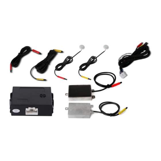
I. Items list Number Item Name Quantity Picture Main Unit 1PCS Main Harness + Extension Cable 1SET Radar Sensor 2PCS LED Indicator 2PCS GPS Antenna 1PCS Buzzer 1PCS 3M Velcro 4PCS Tools for installation: angle gauge; insulation tape; multi-meter; screwdriver; cleaning cloth; tape. -
Page 4: Technical Specification
II. Technical specification Operating frequency 24.0 ----24.25GHZ Transmit power 15dbm Detection range 40 degree ( Horizontal ) Detection ability 5 targets can be detected at the same time Speed range 0.5mph---137mph Speed accuracy < 0.5mph 1. The GPS Antenna when connected activates notifications Speed Restriction over 20mph (Example LED + Speaker) 2. -
Page 5: Wire Connection Diagram
IV. Wire Connection Diagram Black White/gray Black ACC/IGN GPS Ant Yellow Yellow L_sensor Orange Black R_lamp L_LED indicator Pink L_lamp R_sensor R_LED indicator Green Reverse Trigger Buzzer (Optional) -
Page 6: Installation Guide
Fig.2 Step1: Measuring method: Measure the rear bumper using the angle gauge to locate the 20 to 30 Degrees angle. (Fig.3-Fig.4) The microwave sensors are only intended for plastic bumpers. Please note the BSS1 is NOT applicable for metal bumpers. - Page 7 Step2: Locate the desired position for the sensors. (Fig.5 - Fig.6) Step3: Remove the rear bumper to clean the surface for the sensors. (Fig.7) Make sure the surface is clean before Velcro placed with sensors. Fig7 Step4: Place the provided Velcro (To Help Absorb Vibration) on the surface of the sensors (black side) and the desired location on the bumper (See image below).
- Page 8 2. Installation of the left/right turn signal. Step 5. Using the voltage Multi-meter, locate the left and right turn signal trigger wires behind the tail lamp. Once verified, connect the left and right signal wires of the BSS1 wire harness to the correct signal wires.
-
Page 9: Alert Conditions
VI. Alert conditions: 1. When the vehicle is on, the system would start detecting objects in the blind area in the lane next to and behind the vehicle 50 feet. (Fig.16) 2. When vehicles are approaching and their speed is faster than our own speed. Fig.16 VII. -
Page 10: Troubleshooting
VIII. Troubleshooting: Issue Reason Solution LED light does not Incorrect connection or pins Check the harness and make work not making contact sure connection is correct LED light is broken Replace LED light Opposite LED Microwave sensor Make sure RED is driver side and indicator indicators are plugged in to the YELLOW is passenger side. -
Page 11: Limited Warranty
1. Installation by anyone other than an authorized Rydeen Mobile Retailer may void the warranty. 2. Any products distributed outside of the USA by Rydeen North America Inc. (Rydeen) or which is not purchased in the USA or Canada 3. Any product(s) which are purchased from an unauthorized retailer (in-store or online). - Page 12 THIS PAGE INTENTIONALLY LEFT BLANK...
- Page 13 Phone: 1-877-777-8811 Fax: 1-310-943-3778 Copyright © 2017 Rydeen North America Inc. All Rights Reserved. RYDEEN ® is a registered trademark of Rydeen North America Inc. These materials are protected by copyright law and international treaties. Any unauthorized use, reproduction or distribution of these materials, or any portion herein, will result in severe civil and...
Need help?
Do you have a question about the BSS1 and is the answer not in the manual?
Questions and answers