Hitachi Compute Blade 2500 Getting Started Manual
Hide thumbs
Also See for Compute Blade 2500:
- Installation manual (46 pages) ,
- Installation manual (52 pages)

Related Manuals for Hitachi Compute Blade 2500


Summary of Contents for Hitachi Compute Blade 2500
-
Page 1: Getting Started Guide
Hitachi Compute Blade 2500 Series Getting Started Guide Document Organization Product Version Getting Help Contents MK-99CB2500003-12... - Page 2 Hitachi, Ltd. Hitachi, Ltd., reserves the right to make changes to this document at any time without notice and assumes no responsibility for its use. This document contains the most current information available at the time of publication.
-
Page 3: Table Of Contents
Reducing server blade power consumption ............ 1-7 Internal LAN and management LAN .............. 1-7 Various consoles that manage the CB 2500 ............ 1-8 Types of consoles supported by the CB 2500 ........... 1-8 System console prerequisites ................. 1-9 Web console .................... 1-12 CLI console .................... 1-12 Hitachi Compute Blade 2500 Series Getting Started Guide... - Page 4 Preparing the server blades so that they can operate in LP mode ...... 3-11 Powering on the server blade ................ 3-11 Resetting the power of the server blade .............. 3-12 Restarting the BMC of a server blade .............. 3-13 Setting the UEFI of a server blade ............... 3-14 Hitachi Compute Blade 2500 Series Getting Started Guide...
- Page 5 Taking a memory dump with VMware .............. B-5 Configuring the settings to stop VMware when a failure occurs ...... B-6 Taking a memory dump with VMware ............. B-6 C Cleaning the System Unit .............. C-1 Rough guide for cleaning intervals ................ C-2 Hitachi Compute Blade 2500 Series Getting Started Guide...
- Page 6 Removing the dust from the ventilation holes ............ C-2 D Components that have specified lifetimes ........... D-1 Components that have specified lifetimes .............. D-2 E License ..................... E-1 End user license .................... E-2 Glossary Index Hitachi Compute Blade 2500 Series Getting Started Guide...
-
Page 7: Preface
This document describes how to use the Compute Blade 2500 series. This preface includes the following information: Notice: The use of Compute Blade 2500 series and all other Hitachi Data Systems products is governed by the terms of your agreement(s) with Hitachi Data Systems. -
Page 8: Safety Information
Example label 3: Unplug Power Cable Icons represented by indicate required actions. A graphic that indicates the required action, such as Unplug Power Cable, is placed inside . Note that indicates a general, required action. viii Preface Hitachi Compute Blade 2500 Series Getting Started Guide... -
Page 9: Common Precautions Concerning Safety
Do not continuously subject the power cables to ultraviolet or strong ¢ visible light. Do not use damaged power cables. ¢ Do not use the power cables in a high-temperature environment. ¢ Preface Hitachi Compute Blade 2500 Series Getting Started Guide... - Page 10 Inside the power supply slot, some conductors are exposed. Touching them with your hands or tools might cause electric shock or an equipment failure. Abnormal heat, smoke, abnormal noise, or abnormal odors Preface Hitachi Compute Blade 2500 Series Getting Started Guide...
- Page 11 If the system unit has to be installed in 31U or higher in the rack cabinet or the system unit has already been installed there, call for Preface Hitachi Compute Blade 2500 Series Getting Started Guide...
- Page 12 Do not allow clips, pins, or any other metal items or flammable items to enter the equipment through a vent or by any other means. Using the equipment under such conditions can cause an equipment failure. Impacts from drops and falls Preface Hitachi Compute Blade 2500 Series Getting Started Guide...
- Page 13 Do not place a device that generates strong magnetism, such as a magnet or a speaker, near the equipment. If you do so, a system unit failure might occur. Handling of hard disks xiii Preface Hitachi Compute Blade 2500 Series Getting Started Guide...
- Page 14 Notes on rack mount safety ¢ Elevated ambient temperature If you install the system unit in a closed or multi-unit rack assembly, the operating ambient temperature of the rack Preface Hitachi Compute Blade 2500 Series Getting Started Guide...
-
Page 15: Intended Audience
The reader is familiar with the location where the Compute Blade will be installed, including knowledge of physical characteristics, power systems and specifications, and environmental specifications. Product Version This document revision applies to support for Windows 10. Preface Hitachi Compute Blade 2500 Series Getting Started Guide... -
Page 16: Release Notes
Appendix E, License Describes the license terms for the CB 2500, including the license terms for products of other vendors. Preface Hitachi Compute Blade 2500 Series Getting Started Guide... -
Page 17: Referenced Documents
Hitachi Compute Blade Series Hitachi Compute Rack Series OS Installation Guide for Windows Server, MK-99COM076 • Hitachi Compute Blade Series OS Installation Guide for Red Hat Enterprise Linux, MK-99COM141 Document Conventions The term "Compute Blade" refers to all the models of the Compute Blade, unless otherwise noted. -
Page 18: Conventions For Storage Capacity Values
1,024 KB or 1,024 bytes 1 GB 1,024 MB or 1,024 bytes 1 TB 1,024 GB or 1,024 bytes 1 PB 1,024 TB or 1,024 bytes 1 EB 1,024 PB or 1,024 bytes xviii Preface Hitachi Compute Blade 2500 Series Getting Started Guide... -
Page 19: Safety Information
Getting help The Hitachi Data Systems customer support staff is available 24 hours a day, seven days a week. If you need technical support, log on to the Hitachi Data Systems Portal for contact information: https://portal.hds.com Comments Please send us your comments on this document: doc.comments@hds.com. - Page 20 Preface Hitachi Compute Blade 2500 Series Getting Started Guide...
-
Page 21: Cb 2500 Overview
2500 and the various modules to be installed in the CB 2500. □ Features of the CB 2500 □ Various consoles that manage the CB 2500 □ General procedure for setup of the CB 2500 CB 2500 Overview Hitachi Compute Blade 2500 Series Getting Started Guide... -
Page 22: Features Of The Cb 2500
A power supply module supplies power to the system unit. A maximum of 6 power supply modules can be installed in the CB 2500 server chassis. • Fan module CB 2500 Overview Hitachi Compute Blade 2500 Series Getting Started Guide... -
Page 23: Features Of The Server Chassis
8 fan modules and 2 switch modules are installed. 2 cooling fan control modules that control these fan modules are installed. • A maximum of 28 I/O board modules can be installed. CB 2500 Overview Hitachi Compute Blade 2500 Series Getting Started Guide... -
Page 24: Features Of Server Blades
Support high density, high performance optimal for server data centers, virtualization, high-speed computer processing, and flexible I/O capability. • By installing flash storage in a PCI expansion blade, you can configure a high-speed storage system. CB 2500 Overview Hitachi Compute Blade 2500 Series Getting Started Guide... -
Page 25: Management Module Overview
Manual Hitachi Compute Blade Series Hitachi Compute Rack Series OS Installation Guide for Windows Server • Manual Hitachi Compute Blade Series OS Installation Guide for Red Hat Enterprise Linux Management module overview A management module manages the power supply of each module and monitors the status of the system unit. -
Page 26: I/O Board Module
LPARs. You can construct flexible virtual server environments that suit your purposes. For example, for a high-load LPAR, you can use resources in dedicated mode or share them only among limited LPARs. CB 2500 Overview Hitachi Compute Blade 2500 Series Getting Started Guide... -
Page 27: N+M Cold Standby
The reliability of the system unit is enhanced by multiplexing the system. Note that N+M cold standby can be used by linking Hitachi Compute Systems Manager (HCSM), which is an external server management software, with the CB 2500. -
Page 28: Various Consoles That Manage The Cb 2500
LAN so that server blades and switch modules can communicate with the management module. Related topics • Manual Hitachi Compute Blade 2500 Series Management Module User Guide • Setting the network for the server blades and modules on page 3-5... -
Page 29: System Console Prerequisites
The Web console can manage and set all of the equipment installed in a server chassis. The Web console adopts the GUI design that is common to Hitachi storage systems and their storage management software, and provides operability that is standardized over Hitachi's consolidated service platforms. - Page 30 If the TLS 1.1 or TLS 1.2 protocol is used for communication between the remote console and the system unit, use one of the following OSs: Windows 7 or later or Windows Server 2008 R2 or later. 1-10 CB 2500 Overview Hitachi Compute Blade 2500 Series Getting Started Guide...
- Page 31 If you have installed Oracle Java Version 7 Update 21 or later and startup of the remote console is suppressed, use the following method to resolve the suppression. Use the Java Control Panel to change the security level to Medium. ¢ 1-11 CB 2500 Overview Hitachi Compute Blade 2500 Series Getting Started Guide...
-
Page 32: Web Console
Figure 1-4 Web console window The Hitachi Compute Blade 2500 Series Getting Started Guide explains the setting procedures that use the Web console, for the basic settings required when installing server blades and switch modules. For other items that can be... -
Page 33: Remote Console
To use the LCD touch console, connect it to the USB port of the management module on the front surface of the server chassis. Figure 1-5 LCD touch console connection 1-13 CB 2500 Overview Hitachi Compute Blade 2500 Series Getting Started Guide... -
Page 34: General Procedure For Setup Of The Cb 2500
The following figure shows the general procedure from powering on a server blade to setting up the OS. For details on the tasks in LP mode, see the Hitachi Compute Blade 2500 Series Logical partitioning manager User Guide. 1-14 CB 2500 Overview... -
Page 35: Stopping The Running System Unit
For details on the tasks in LP mode, see the Hitachi Compute Blade 2500 Series Logical partitioning manager User Guide. 1-15... - Page 36 Figure 1-8 General procedure for stopping the system unit 1-16 CB 2500 Overview Hitachi Compute Blade 2500 Series Getting Started Guide...
-
Page 37: Cb 2500 Appearance
□ Appearance of the management module □ Appearance of the management LAN module □ Appearance of the switch module □ Appearance of the power supply module □ Appearance of the fan module CB 2500 Appearance Hitachi Compute Blade 2500 Series Getting Started Guide... -
Page 38: Appearance Of The Server Chassis
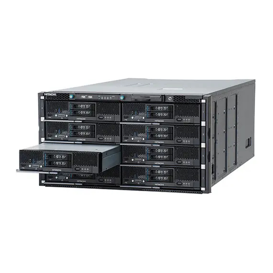
The following figures show the locations where server blades and modules are installed, for the front and rear sides of the server chassis. Figure 2-1 Server chassis (front side) and modules CB 2500 Appearance Hitachi Compute Blade 2500 Series Getting Started Guide... -
Page 39: Id Tag Of The Server Chassis
This section describes the slots in which server blades and modules are installed and the location tags. The following figure shows slots and their slot numbers on the front of the server chassis. CB 2500 Appearance Hitachi Compute Blade 2500 Series Getting Started Guide... - Page 40 Therefore, when a PCI expansion blade is used, half-wide blades are installed in odd-numbered slots, PCI expansion blades are installed in even-numbered slots, and then each blade is connected to a corresponding I/O adapter. CB 2500 Appearance Hitachi Compute Blade 2500 Series Getting Started Guide...
-
Page 41: Server Blade Appearance
A full-wide blade has slots for installing HDDs and SSDs, as well as connectors for connecting external devices. It also has indicators to show the operational status of the server blade. The appearance of a full-wide blade is shown below. CB 2500 Appearance Hitachi Compute Blade 2500 Series Getting Started Guide... - Page 42 The drive is idle. Flashing green The drive is running or is being accessed. The drive is being rebuilt (source drive). Fault lamp Orange light on An error occurred on the drive. CB 2500 Appearance Hitachi Compute Blade 2500 Series Getting Started Guide...
- Page 43 The BMC has been initialized and the server blade has been powered off. Light on ¢ The server blade is powered on. Light off ¢ The server blade is powered off. CB 2500 Appearance Hitachi Compute Blade 2500 Series Getting Started Guide...
- Page 44 This LED lights up when hardware in the server blade needs to be replaced. PRM LED (white LED) This LED lights up when the server blade is set as the primary server blade. CB 2500 Appearance Hitachi Compute Blade 2500 Series Getting Started Guide...
-
Page 45: Appearance Of A Half-Wide Blade
A half-wide blade has slots for installing HDDs and SSDs, as well as connectors for connecting external devices. It also has indicators to show the operational status of the server blade. The appearance of a half-wide blade is shown below. CB 2500 Appearance Hitachi Compute Blade 2500 Series Getting Started Guide... - Page 46 Figure 2-14 ID tags of half-wide blades Figure 2-15 Switch and connector of a half-wide HDD slots 0 and 1 These are slots for installing HDDs on the server blade. 2-10 CB 2500 Appearance Hitachi Compute Blade 2500 Series Getting Started Guide...
- Page 47 BMC of the server blade is being initialized. Slow flashing ¢ The BMC has been initialized and the server blade has been powered off. Light on ¢ The server blade is powered on. 2-11 CB 2500 Appearance Hitachi Compute Blade 2500 Series Getting Started Guide...
-
Page 48: Appearance Of A Pci Expansion Blade
Appearance of a PCI expansion blade A PCI expansion blade has slots that are used to install one or more I/O adapters. The following figure shows the appearance of a PCI expansion blade. 2-12 CB 2500 Appearance Hitachi Compute Blade 2500 Series Getting Started Guide... -
Page 49: About Network Devices Installed In A Server Blade
Function number connection number installation destination locations Broadcom 1Gb 4- Switch module 1 8(08h) port Switch module 2 Mezzanine card slot 1 Switch module 1 2-13 CB 2500 Appearance Hitachi Compute Blade 2500 Series Getting Started Guide... - Page 50 SMP configurations support only CB 520X B1 server blades. 2-blade SMP configuration ¢ Node #1: 69(45h) Node #2: 197(C5h) 4-blade SMP configuration ¢ Node #1: 37(25h) Node #2: 101(65h) Node #3: 165(A5h) Node #4: 229(E5h) 2-14 CB 2500 Appearance Hitachi Compute Blade 2500 Series Getting Started Guide...
- Page 51 Mezzanine card slot #3: 33(21h) Node #2 Mezzanine card slot #1: 72(48h) Mezzanine card slot #3: 97(61h) Node #3 Mezzanine card slot #1: 136(88h) Mezzanine card slot #3: 161(A1h) 2-15 CB 2500 Appearance Hitachi Compute Blade 2500 Series Getting Started Guide...
-
Page 52: Appearance Of The I/O Board Module
Figure 2-19 I/O board module and PCI Express adapter appearance The I/O board module has some indicators. The indicators on the I/O board module are as described below. 2-16 CB 2500 Appearance Hitachi Compute Blade 2500 Series Getting Started Guide... - Page 53 Full-wide blade Installation number of Corresponding I/O board module slot number mezzanine cards slot number 01A, 01B 02A, 02B 03A, 03B 04A, 04B 05A, 05B 06A, 06B 07A, 07B 2-17 CB 2500 Appearance Hitachi Compute Blade 2500 Series Getting Started Guide...
-
Page 54: Appearance Of The Management Module
The appearance of the management module is shown below. Figure 2-21 Management module The switches, indicators, and connectors of the management module are described below. 2-18 CB 2500 Appearance Hitachi Compute Blade 2500 Series Getting Started Guide... - Page 55 ¢ server chassis has been powered on. OFF: The server chassis is powered off. ¢ On the standby management module, this LED is always off. System WRN LED 2-19 CB 2500 Appearance Hitachi Compute Blade 2500 Series Getting Started Guide...
-
Page 56: Appearance Of The Management Lan Module
Figure 2-23 Management LAN module The connectors and indicators on the management LAN module are described below. Figure 2-24 Management LAN module connectors and indicators MGMT1 port, MGMT2 port 2-20 CB 2500 Appearance Hitachi Compute Blade 2500 Series Getting Started Guide... -
Page 57: Appearance Of The Switch Module
The appearance of the 1/10Gb LAN switch module is shown below. Figure 2-25 1/10Gb LAN switch module The connectors and indicators of the 1/10Gb LAN switch module are described below. 2-21 CB 2500 Appearance Hitachi Compute Blade 2500 Series Getting Started Guide... -
Page 58: Appearance Of The Brocade 10Gb Dcb Switch Module
Appearance of the Brocade 10Gb DCB switch module The appearance of the Brocade 10Gb DCB switch module is shown below. 2-22 CB 2500 Appearance Hitachi Compute Blade 2500 Series Getting Started Guide... - Page 59 QSFP port (Trunk group C) These optical transceiver ports connect to an external network. QSFP ports 57 to 58 belong to Trunk group C. 2-23 CB 2500 Appearance Hitachi Compute Blade 2500 Series Getting Started Guide...
-
Page 60: Appearance Of The Power Supply Module
The appearance of the power supply module is shown below. Figure 2-29 Power supply module The connectors and indicators of the power supply module are described below. Figure 2-30 Power supply module connector and indicators 2-24 CB 2500 Appearance Hitachi Compute Blade 2500 Series Getting Started Guide... -
Page 61: Appearance Of The Fan Module
This is an IEC60320/C20-compliant connector. Appearance of the fan module Fan modules have indicators to show their operational statuses. The connectors and indicators of the fan module are described below. 2-25 CB 2500 Appearance Hitachi Compute Blade 2500 Series Getting Started Guide... - Page 62 The indicators of the fan module are described below. PWR LED This LED lights up when the fan module is powered on. ARM LED This LED lights up when a failure occurs on the fan module. 2-26 CB 2500 Appearance Hitachi Compute Blade 2500 Series Getting Started Guide...
-
Page 63: Starting The Cb 2500 And Performing Initial Setup
□ Resetting the power of the server blade □ Restarting the BMC of a server blade □ Setting the UEFI of a server blade Starting the CB 2500 and Performing Initial Setup Hitachi Compute Blade 2500 Series Getting Started Guide... -
Page 64: Connecting The System Unit To The Power Supply
LAN. This section describes the preparation for using the system console to manage the system unit. Starting the CB 2500 and Performing Initial Setup Hitachi Compute Blade 2500 Series Getting Started Guide... -
Page 65: Setting The Web Browser Used To Display The Web Console
You can use the serial port of the management module to log in to CLI console. For more information of those commands, see the manual Hitachi Compute Blade 2500 Series Management Module User Guide. -
Page 66: Management Lan When Lpar Manager Is Used
LAN module. • Connect the network device used by LPAR manager for management communications, to the management LAN. See the related topics for more information. Starting the CB 2500 and Performing Initial Setup Hitachi Compute Blade 2500 Series Getting Started Guide... -
Page 67: Setting The Network Information Of The System Console
This manual describes only the minimum settings required for the system unit when installing it for the first time. For detailed information on configuring other settings and operations via the management module, see the manual Hitachi Compute Blade 2500 Series Management Module User Guide. Related topics •... -
Page 68: Changing The Password Used To Log In To The Management Module
Password field, and then enter the same password again in the Retype Password field. In the Edit Account dialog box, click the OK button to change the password. Starting the CB 2500 and Performing Initial Setup Hitachi Compute Blade 2500 Series Getting Started Guide... -
Page 69: Setting The Chassis Id Of The Server Chassis
Ensure that the IP addresses that you have entered will not conflict with the resources that you will connect to the management LAN network later. Starting the CB 2500 and Performing Initial Setup Hitachi Compute Blade 2500 Series Getting Started Guide... -
Page 70: Setting A User Account For The Lan Switch Module
When the terminal software displays the prompt login: type admin and press Enter. The following response is displayed: password: Type admin and press Enter. You are now successfully logged in. Starting the CB 2500 and Performing Initial Setup Hitachi Compute Blade 2500 Series Getting Started Guide... -
Page 71: Setting A User Account For The Brocade 10Gb Dcb Switch Module
"admin") to ensure the security for the switch. To do this, follow the procedure described below. Log in to the switch module. Reset the password for the initial "admin" account. Log out from the switch module. Starting the CB 2500 and Performing Initial Setup Hitachi Compute Blade 2500 Series Getting Started Guide... -
Page 72: Connecting The System Console And The System Unit To The Management Lan
LAN. Once they are connected, you can manage the system unit remotely via the management LAN network. 3-10 Starting the CB 2500 and Performing Initial Setup Hitachi Compute Blade 2500 Series Getting Started Guide... -
Page 73: Preparing The Server Blades So That They Can Operate In Lp Mode
LP mode, in which the LPAR manager functionality is applied. For more information on the settings and operating methods for applying the LPAR manager functionality, see the manual Hitachi Compute Blade 2500 Series Logical partitioning manager User Guide. Related topics •... -
Page 74: Resetting The Power Of The Server Blade
You can reset the power of the server blade from the Web console or CLI console. You can also reset the power of the server blade by using Hitachi Compute Systems Manager. -
Page 75: Restarting The Bmc Of A Server Blade
Start the remote console and log in to the desired server blade. In the Power menu, click Hard Reset. Related topics • The section on the reset blade command in the manual Hitachi Compute Blade 2500 Series Management Module User Guide • Functionality of the remote console on page 5-7 Restarting the BMC of a server blade If a failure occurs in the server blade, restart the BMC of the server blade. -
Page 76: Setting The Uefi Of A Server Blade
Set up the PXE boot environment or iSCSI boot environment. For more information on using UEFI to configure these environmental settings on the server blade, see the manual Hitachi Compute Blade 2500 Series UEFI Setup Guide. The setup menu for configuring UEFI on the server blade can be opened from the remote console while the server blade is starting. -
Page 77: Stopping The Cb 2500
This chapter explains how to stop the system unit. □ Powering off a server blade □ Forcibly powering off a server blade □ Powering off a switch module □ Powering off the server chassis Stopping the CB 2500 Hitachi Compute Blade 2500 Series Getting Started Guide... -
Page 78: Powering Off A Server Blade
This section describes the procedure for powering off a server blade that is running in the Basic mode. For details on how to power off a server blade that is running in LP mode, see the Hitachi Compute Blade 2500 Series Logical partitioning manager User Guide. -
Page 79: Forcibly Powering Off A Server Blade
Using the CLI console to forcibly power off a server blade Execute the poweroff blade -h command. For more information about the poweroff blade command, see the Hitachi Compute Blade 2500 Series Management Module User Guide. Using the remote console to forcibly power off a server blade Start the remote console and log in to the desired server blade. -
Page 80: Powering Off The Server Chassis
Using the CLI console to power off the server chassis Execute the shutdown chassis command. For more information about the shutdown chassis command, see the Hitachi Compute Blade 2500 Series Management Module User Guide. Using the LCD touch console to power off the server chassis First, ensure that the LCD touch console is connected to the USB port of the management module for the active system. - Page 81 Down Chassis, and then touch the Operate button. The Shutting Down Server Chassis window is displayed. Related topics • The section on the shutdown chassis command, in the Hitachi Compute Blade 2500 Series Management Module User Guide • Appearance of the management module on page 2-18...
- Page 82 Stopping the CB 2500 Hitachi Compute Blade 2500 Series Getting Started Guide...
-
Page 83: Functionality And Operation Of The Remote Console
□ Functionality of the remote console □ Creating a disk image for access from the server blade □ Exiting the remote console □ Screen messages displayed by the remote console Functionality and Operation of the Remote Console Hitachi Compute Blade 2500 Series Getting Started Guide... -
Page 84: Notes On Using The Remote Console
If the connection with the remote console is terminated, it might become impossible to read or write the Functionality and Operation of the Remote Console Hitachi Compute Blade 2500 Series Getting Started Guide... -
Page 85: Server Blade Image Signals That Can Be Displayed On The Remote Console
To enable display on the remote console, VGA settings are required on the server blade side. These settings are as follows. Functionality and Operation of the Remote Console Hitachi Compute Blade 2500 Series Getting Started Guide... -
Page 86: Starting The Remote Console
In Finder, from the Go menu, execute the Utilities command. The Utilities window opens. In the Utilities window, execute the Terminal icon. The Terminal window opens. In the Terminal window, enter the following commands: Functionality and Operation of the Remote Console Hitachi Compute Blade 2500 Series Getting Started Guide... -
Page 87: Starting The Remote Console From The Management Module Via A Web Console
In the Server Blade n Information view, select the Status tab, and then from the Server Blade Operation drop-down list, select Start Remote Console. Functionality and Operation of the Remote Console Hitachi Compute Blade 2500 Series Getting Started Guide... -
Page 88: Starting The Remote Console From The Web Console On A Server Blade
In the Remote Console Launch window, click Launch Remote Console. Related topics • Hitachi Compute Blade 2500 Series Management Module User Guide manual Remote console window This section describes the remote console window and the information displayed in the window. -
Page 89: Functionality Of The Remote Console
Maximize the View Full Screen command remote console menu window. Restore the View Windowed command maximized remote menu Functionality and Operation of the Remote Console Hitachi Compute Blade 2500 Series Getting Started Guide... - Page 90 Functionality and Operation of the Remote Console Hitachi Compute Blade 2500 Series Getting Started Guide...
- Page 91 If the resolution setting for the VGA window of the server blade exceeds that of the system console window, the Full Screen command cannot be executed. Functionality and Operation of the Remote Console Hitachi Compute Blade 2500 Series Getting Started Guide...
-
Page 92: Creating A Disk Image For Access From The Server Blade
From the Tools menu of the remote console, execute the Launch Virtual Media command. Items in the Virtual Media console This section describes the window and functionality of the Virtual Media console. 5-10 Functionality and Operation of the Remote Console Hitachi Compute Blade 2500 Series Getting Started Guide... - Page 93 Read Bytes column This column displays the amount of data that the server blade has read from the virtual media. Write Bytes column 5-11 Functionality and Operation of the Remote Console Hitachi Compute Blade 2500 Series Getting Started Guide...
-
Page 94: Notes On Creating Disk Images
Disk images created using the image creation tools (FDDUMP.exe and MakeCDImg.exe) can only be used for the virtual media functionality of the remote console. If you use a disk image for any other purpose and any problem arises as a result, Hitachi will accept no responsibility or liability. •... - Page 95 (FDDUMP.exe or MakeCDImg.exe). These tools are stored in the flash memory mounted on the server chassis. To use the tools, download them onto the system console. Hitachi cannot guarantee that image files created using other tools will function correctly with the virtual media functionality.
-
Page 96: Creating A Disk Image From Cd/Dvd Media
100%, the image file has been created. Exiting the remote console Exit the remote console. In the File menu of the remote console, click Exit. 5-14 Functionality and Operation of the Remote Console Hitachi Compute Blade 2500 Series Getting Started Guide... -
Page 97: Screen Messages Displayed By The Remote Console
VideoStopped_OutOfRange The VGA signal sent from the server blade was interrupted or the VGA signal became unavailable for display on the remote console. 5-15 Functionality and Operation of the Remote Console Hitachi Compute Blade 2500 Series Getting Started Guide... - Page 98 5-16 Functionality and Operation of the Remote Console Hitachi Compute Blade 2500 Series Getting Started Guide...
-
Page 99: Troubleshooting
Troubleshooting This chapter describes troubleshooting procedures for the CB 2500. □ Troubleshooting on the remote console □ Issuing an NMI for the operating system running on the server blade Troubleshooting Hitachi Compute Blade 2500 Series Getting Started Guide... -
Page 100: Troubleshooting On The Remote Console
The remote screen might not display "No blade, the VGA window of the Signal", even after the server blade is powered server blades is still displayed. off. In this case, check the status bar of the Troubleshooting Hitachi Compute Blade 2500 Series Getting Started Guide... - Page 101 If connected server blade does the problem persists, switch to a different not respond to mouse input. mouse mode and then revert to the correct Troubleshooting Hitachi Compute Blade 2500 Series Getting Started Guide...
- Page 102 Press the USB Reset button on the virtual media by using the operating system console to reset the virtual drive. on the server blade, the operating system no longer recognizes the virtual drive after it is reconnected. Troubleshooting Hitachi Compute Blade 2500 Series Getting Started Guide...
- Page 103 OS X system console. Next, in the Web browser, access the Java Web However, you cannot connect Start application, which is located in the to the remote console because following path: Troubleshooting Hitachi Compute Blade 2500 Series Getting Started Guide...
-
Page 104: Issuing An Nmi For The Operating System Running On The Server Blade
Issue NMI button. Issuing an NMI from the CLI console Execute the reset blade -s command. For more information about the reset blade command, see the Hitachi Compute Blade 2500 Series Management Module User Guide. Troubleshooting Hitachi Compute Blade 2500 Series Getting Started Guide... - Page 105 Related topic • Hitachi Compute Blade 2500 Series Management Module User Guide, reset blade Troubleshooting Hitachi Compute Blade 2500 Series Getting Started Guide...
- Page 106 Troubleshooting Hitachi Compute Blade 2500 Series Getting Started Guide...
-
Page 107: A System Unit Specifications
This appendix describes the specifications of the system unit components. □ Specifications of the server chassis □ Specifications of server blades □ Specifications of switch modules □ Specifications of the power supply module □ Specifications of fan modules System Unit Specifications Hitachi Compute Blade 2500 Series Getting Started Guide... -
Page 108: Specifications Of The Server Chassis
Air suction port: Front side Air exhaust port: Rear side Flow rate 14.4 m3 / min Specifications of server blades The following table shows the specifications of server blades. System Unit Specifications Hitachi Compute Blade 2500 Series Getting Started Guide... - Page 109 Display resolution 640 x 400 to 1,680 x 1,050 Refresh rate 60 Hz to 85 Hz Color depth 8 bpp, 16 bpp, 32 bpp Internal USB port USB 2.0 x 2 ports (for LPAR manager) System Unit Specifications Hitachi Compute Blade 2500 Series Getting Started Guide...
- Page 110 3.2 GHz QPI frequency 9.6 GT/s 9.6 GT/s 9.6 GT/s L3 Cache 45 M 45 M 45 M 150 W 165 W 140 W Number of CPUs Maximum: 2 System Unit Specifications Hitachi Compute Blade 2500 Series Getting Started Guide...
- Page 111 FCoE Mezzanine card Number of slots 4 slot Management function Remote console Supported Serial redirection DC input supply voltage DC + 12 V Front interface 1 (USB 3.0) System Unit Specifications Hitachi Compute Blade 2500 Series Getting Started Guide...
- Page 112 Independent Mode (Default), Lockstep Mode, Rank Sparing Mode, Mirrored Memory Mode Number of slots Memory capacity Maximum: 1,536 GB (32 GB x 48) 3,072 GB (64 GB x 48) System Unit Specifications Hitachi Compute Blade 2500 Series Getting Started Guide...
- Page 113 In SMP configuration between blades, VGA and COM are not available and only USB port is available on non-primary server blades. The Weight of a server blade includes that of SMP connection board. System Unit Specifications Hitachi Compute Blade 2500 Series Getting Started Guide...
- Page 114 Memory capacity Maximum: 768 GB(RDIMM 32GB x24) 1536 GB(LR-DIMM 64 GB x 24) Memory frequency 2133, 1866, 1600 MT/s HDD/SSD Number of HDDs Maximum: 2 Maximum: 3.6 TB Capacity System Unit Specifications Hitachi Compute Blade 2500 Series Getting Started Guide...
- Page 115 Number of cores 12 C 16 C CPU frequency 3.5 GHz 3.4 GHz 2.2 GHz 3.2 GHz 2.1 GHz QPI frequency 9.6 GT/s 9.6 GT/s 9.6 GT/s 9.6 GT/s 9.6 GT/s System Unit Specifications Hitachi Compute Blade 2500 Series Getting Started Guide...
- Page 116 Maximum: 2 Maximum: 3.6 TB Capacity Internal disk I/F Controller LSI SAS 3004 SAS (SATA is not supported) Number of I/F Maximum: 2 (2.5 inch SAS HDD, SSD) A-10 System Unit Specifications Hitachi Compute Blade 2500 Series Getting Started Guide...
- Page 117 - Low profile (MD2) slots: 4 (I/O adapter slot 2/3/4/5) I/O adapter slot 0 Electrical x8/Physical x8; Maximum: 25 W I/O adapter slot 1 - Electrical x16/Physical x16; Maximum: 225W (PCI expansion blade ((x16 FH 1slot))) A-11 System Unit Specifications Hitachi Compute Blade 2500 Series Getting Started Guide...
-
Page 118: Specifications Of Switch Modules
SerDes 1000Base-X×2 port (for connecting port management modules) • RS232C Serial port×1port (Connector: mini-USB) Layer 2 VLAN • VLAN(IEEE802.1Q) functionality • Private VLAN Spanning Tree • STP(IEEE802.1D) Protocol (STP) • RSTP(IEEE802.1w) A-12 System Unit Specifications Hitachi Compute Blade 2500 Series Getting Started Guide... - Page 119 Simple Network Management Protocol and monitoring functionality (SNMP v1/v2/v3) • Telnet interface for CLI • SSH and SSH v2 for CLI • Serial interface for CLI • HTTP browser for GUI A-13 System Unit Specifications Hitachi Compute Blade 2500 Series Getting Started Guide...
- Page 120 40GBASE-SR4 (QSFP+)×2 port (default:0 port) Management LAN • SerDes 1000Base-X×2 port (for connecting port management modules) • RS232C Serial port×1port (Connector: mini-USB) Layer 2 VLAN • VLAN(IEEE802.1Q) functionality • Private VLAN A-14 System Unit Specifications Hitachi Compute Blade 2500 Series Getting Started Guide...
- Page 121 Automatic Migration of Port Profiles(AMPP) • VMware-aware Network Automation Other network • IEEE802.1p Class of Service(CoS) functionality • Eight queues per port • Per-port QoS configuration • Scheduling:Strict Priority(SP), Deficit Weighted Round-Robin(DWRR) A-15 System Unit Specifications Hitachi Compute Blade 2500 Series Getting Started Guide...
-
Page 122: Specifications Of The Power Supply Module
(the settings at shipping time). Using this port requires a dedicated serial management cable. Specifications of the power supply module The following table shows the specifications of the power supply module. A-16 System Unit Specifications Hitachi Compute Blade 2500 Series Getting Started Guide... -
Page 123: Specifications Of Fan Modules
Support for N+1 redundant configuration Fan control type Fan speed is controlled by the thermal sensor and the power supply. Fan speed detection Install a detector for each fan. Air filter Optional A-17 System Unit Specifications Hitachi Compute Blade 2500 Series Getting Started Guide... - Page 124 A-18 System Unit Specifications Hitachi Compute Blade 2500 Series Getting Started Guide...
-
Page 125: B Taking A Memory Dump Of The Os Running On A Server Blade
□ Taking a memory dump in Windows □ Taking a memory dump in Linux □ Taking a memory dump with VMware Taking a Memory Dump of the OS Running on a Server Blade Hitachi Compute Blade 2500 Series Getting Started Guide... -
Page 126: Taking A Memory Dump In Windows
If you have purchased a pre-installed edition or bundled installation service edition, or have installed the OS by using the OS setup functionality (Installation Assistant) of Hitachi Server Navigator, which is bundled with the system unit, the settings for taking a memory dump are configured automatically. -
Page 127: Configuring The Settings For Taking A Complete Memory Dump
Close the Startup and Recovery window and the System Properties window, and then restart Windows. Related topics • Setting the Windows system environment on page B-2 Taking a Memory Dump of the OS Running on a Server Blade Hitachi Compute Blade 2500 Series Getting Started Guide... -
Page 128: Taking A Memory Dump In Windows
See the following registry information to check the current output destination. Key: HKEY_LOCAL_MACHINE\System\CurrentControlSet\Control \CrashControl Name: DumpFile Taking a Memory Dump of the OS Running on a Server Blade Hitachi Compute Blade 2500 Series Getting Started Guide... -
Page 129: Taking A Memory Dump In Linux
OS setting file /etc/ kdump.conf. Taking a memory dump with VMware This section describes the procedure to take a memory dump with VMware. Taking a Memory Dump of the OS Running on a Server Blade Hitachi Compute Blade 2500 Series Getting Started Guide... -
Page 130: Configuring The Settings To Stop Vmware When A Failure Occurs
In vmkernel debugger, type "reboot" and then press the Enter key. • For ESXi 5.0 or earlier Press the Esc key. Taking a Memory Dump of the OS Running on a Server Blade Hitachi Compute Blade 2500 Series Getting Started Guide... - Page 131 If you do not plan to start the virtual machine, start the system in maintenance mode. Taking a Memory Dump of the OS Running on a Server Blade Hitachi Compute Blade 2500 Series Getting Started Guide...
- Page 132 Taking a Memory Dump of the OS Running on a Server Blade Hitachi Compute Blade 2500 Series Getting Started Guide...
-
Page 133: C Cleaning The System Unit
Cleaning the System Unit This appendix describes how to clean the system unit. □ Rough guide for cleaning intervals □ Removing the dust from the ventilation holes Cleaning the System Unit Hitachi Compute Blade 2500 Series Getting Started Guide... -
Page 134: Rough Guide For Cleaning Intervals
Use a dry cloth to wipe the ventilation holes in the locations shown below, or use a vacuum cleaner to vacuum the dust. Figure C-1 Ventilation holes to be cleaned Cleaning the System Unit Hitachi Compute Blade 2500 Series Getting Started Guide... -
Page 135: D Components That Have Specified Lifetimes
This appendix describes the service life of the hardware components making up the system unit, and the components that have specified lifetimes. □ Components that have specified lifetimes Components that have specified lifetimes Hitachi Compute Blade 2500 Series Getting Started Guide... - Page 136 Not applicable Note: The service life periods described here are only rough guides and do not guarantee that failures will not occur during these periods. Components that have specified lifetimes Hitachi Compute Blade 2500 Series Getting Started Guide...
-
Page 137: E License
License This appendix describes the license terms for the CB 2500, including the license terms for products of other vendors. □ End user license License Hitachi Compute Blade 2500 Series Getting Started Guide... -
Page 138: End User License
Avocent, (iii) the end user shall safeguard the confidentiality of the Licensed Products, and (iv) that neither Avocent nor Distributor shall be liable for any special, indirect, incidental, or consequential damages. License Hitachi Compute Blade 2500 Series Getting Started Guide... -
Page 139: Glossary
A controller that monitors and controls the status of server blades. The BMC monitors and controls server blades by connecting to the system console and the management module. Command Line Interface Converged Network Adapter Glossary-1 Hitachi Compute Blade 2500 Series Getting Started Guide... - Page 140 Double-Data-Rate3 Deployment Manager Software provided as part of Hitachi Compute Systems Manager. Deployment Manager is a function that allows you to back up and restore the disk data of a server blade as an image file. You can also use a backed up image file to replicate the environment of a managed resource on another managed resource.
- Page 141 The Institute of Electrical and Electronics Engineers, Inc. IPv4 Internet Protocol version 4 IPv6 Internet Protocol version 6 iSCSI Internet Small Computer System Interface Java Runtime Environment Keyboard, Video and Mouse Glossary-3 Hitachi Compute Blade 2500 Series Getting Started Guide...
-
Page 142: Logical Partitioning
An LED lamp that you can use to identify the location of server chassis and modules. By controlling the LIDs of a server blade or server chassis remotely from the system console or Hitachi Compute Systems Manager, you can easily identify a managed resource in the system unit. - Page 143 A hardware interrupt issued to the CPU from an external device. An NMI can be used, for example, to collect OS dump files. Network Time Protocol Peripheral Component Interconnect PCIe PCI Express Priority Flow Control Preboot eXecution Environment QuickPath Interconnect Glossary-5 Hitachi Compute Blade 2500 Series Getting Started Guide...
-
Page 144: Server Chassis
When using the N+M cold standby function, the standby blade remains in standby with its power off until a failover occurs from a failed active blade. system console A computer from which a user monitors and configures the CB 2500 system unit. Glossary-6 Hitachi Compute Blade 2500 Series Getting Started Guide... -
Page 145: Switch Module
A console that runs in a Web browser. You can use the Web console to view hardware information for a server chassis or server blade, or to control the hardware remotely. Glossary-7 Hitachi Compute Blade 2500 Series Getting Started Guide... - Page 146 Wake-on LAN Glossary-8 Hitachi Compute Blade 2500 Series Getting Started Guide...
-
Page 147: Index
2-17 full-wide blade Auto Run functionality 5-13 half-wide blade 2-10 connectors management LAN module 2-20 management module 2-19 backplane power supply module 2-24 Basic mode 3-11 console CLI console 1-9, 1-12 Index-1 Hitachi Compute Blade 2500 Series Getting Started Guide... - Page 148 LAN connector iSCSI boot environment 3-14 ID tag issuing an NMI switch Java VM 1-11 general procedure for setup 1-14 global tabs 1-12 Index-2 Hitachi Compute Blade 2500 Series Getting Started Guide...
- Page 149 OUT LED 2-25 connecting by using RS232C cable connectors 2-19 indicators 2-19 logging in PCI expansion blade 1-2, 2-12 MM ALM LED 2-19 appearance 2-13 MM HB LED 2-20 PCI Express adapter Index-3 Hitachi Compute Blade 2500 Series Getting Started Guide...
- Page 150 2-8, 2-12 ID tag ATN LED 2-8, 2-12 installation locations Basic mode 3-11 location tag changing network address setting the chassis ID Diagnostic Panel slot 2-4, 2-5 ERR SMP LED standby slot Index-4 Hitachi Compute Blade 2500 Series Getting Started Guide...
- Page 151 LID LED 2-19 system PWR LED 2-19 system unit cleaning connecting to management LAN 3-10 connecting to power supply system WRN LED 2-19 taking memory dump Linux VMware Windows TEMP LED troubleshooting Index-5 Hitachi Compute Blade 2500 Series Getting Started Guide...
- Page 152 Index-6 Hitachi Compute Blade 2500 Series Getting Started Guide...
- Page 153 Hitachi Compute Blade 2500 Series Getting Started Guide...
- Page 154 Hitachi Data Systems Corporate Headquarters 2845 Lafayette Street Santa Clara, California 95050-2639 U.S.A. www.hds.com Regional Contact Information Americas +1 408 970 1000 info@hds.com Europe, Middle East, and Africa +44 (0)1753 618000 info.emea@hds.com Asia Pacific +852 3189 7900 hds.marketing.apac@hds.com MK-99CB2500003-12...