Electrolux T4900 Service Manual
Hide thumbs
Also See for T4900:
- Installation manual (44 pages) ,
- Specifications (2 pages) ,
- Service manual (70 pages)
Chapters
Table of Contents

Related Manuals for Electrolux T4900


Summary of Contents for Electrolux T4900
- Page 1 Service manual Tumble dryers T4900, T41200 TD100, TD135 Type N4... Dryer type T4900/TD100 from serial number: 00900/0100000 Dryer type T41200/TD135 from serial number: 01200/0100000 487 05 46 91/EN Original instructions 2015.02.03...
- Page 3 DRAWER OR NEAR THIS APPLIANCE. DO NOT SPRAY AEROSOLS IN THE VICINITY OF THIS APPLIANCE WHILE IT IS IN OPERATION. DO NOT MODIFY THIS APPLIANCE. For parts, service and technical assistance please contact: Electrolux Laundry Systems 5-7 Keith Champbell Crt Scoresby Victoria 3179...
- Page 4 Service Additional safety instructions and warnings manual To minimize the risk of fire in a tumble dryer, the following should be observed: • Items that have been spotted or soaked with vegetable or cooking oil constitute a fire hazard and should not be placed in a tumble dryer. • Oil-affected items can ignite spontaneously, especially when exposed to heat sources such as in a tumble dryer.
-
Page 5: Table Of Contents
Service manual Contents Safety Precautions........7 Technical data . - Page 6 Service manual Safety Precautions This appliance can be used by children aged from 8 years and above and persons with reduced physical, sensory or mental capabilities or lack of experience and knowledge if they have been given supervision or instruction concerning use of the appliance in a safe way and understand the hazards involved Children shall not play with the appliance.
- Page 7 Service Safety Precautions manual WARNING. Never stop the machine before the end of the drying cycle unless all items are quickly removed and spread out so that the heat is dissipated. Adequate ventilation has to be provided to avoid the back flow of gases into the room for appliances burning other fuels, including open fires.
-
Page 8: Safety Precautions
Service manual Safety Precautions Gas heated tumble dryer: Before installation, check that the local distribution conditions, nature of gas and pressure and the adjustment of the appliance are compatible. The machine is not to be installed in rooms containing cleaning machines with perchloroethylene, TRICHLOROETHYLENE or CHLOROFLUOROCONTAINING HYDROCARBONS as cleaning agents. - Page 9 Contents Technical data - type T4900 ....... . . 10 Technical data - type T41200 ....... . 11 Technical data - type TD100 .
-
Page 10: Technical Data - Type T4900
Service Technical data manual Technical data - type T4900 Heating Steam Electric Drum volume: 900 litres 900 litres 900 litres Weight net: Basic: Standard door 545 kg 545 kg 545 kg Basic: Sliding Door 599 kg 599 kg 599 kg... -
Page 11: Technical Data - Type T41200
Service Technical data manual Technical data - type T41200 Heating Steam Electric Drum volume: 1200 litres 1200 litres 1200 litres Weight net: Basic: Standard door 580 kg 580 kg 580 kg Basic: Sliding Door 634 kg 634 kg 634 kg Heating unit 46 kg 50 kg... -
Page 12: Technical Data - Type Td100
Service Technical data manual Technical data - type TD100 Heating Steam Electric Drum volume: (900 litres) 32 cu.ft 32 cu.ft 32 cu.ft Basic: Standard door 1202 lb 1202 lb 1202 lb Weight net: Basic: Sliding Door 1321 lb 1321 lb 1321 lb Heating unit 86 lb... -
Page 13: Technical Data - Type Td135
Service Technical data manual Technical data - type TD135 Heating Steam Electric Drum volume: (1200 litres) 42.4 cu.ft 42.4 cu.ft 42.4 cu.ft Basic: Standard door 1279 lb 1279 lb 1279 lb Weight net: Basic: Sliding Door 1398 lb 1398 lb 1398 lb Heating unit 101 lb... - Page 15 Service Description of principal components manual Contents Machine description ........16...
-
Page 16: Description Of Principal Components
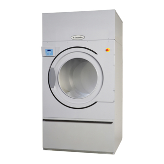
Service Description of principal components manual Machine description Dryer types T4900 / TD100 and T41200 / TD135 are available as electric, gas or steam heated. They are supplied with either standard door or with Sliding Door. Sliding Door can also be fitted with tilting function. Programs - Selecta Control The dryer has a microprocessor. The microprocessor control has different functions including: • Drum reversing for less tangling of large items. • An anticrease function which engages after the end of the program sequence. • Dryer functions monitoring - errors occurred during the program sequence are registered in the log. Some error codes are shown on the display at the same time. • Autostop, the dryer stops automatically when the clothes are dry. Heating unit Gas reset button (active on gas Emergency stop dryers only) Operating control box Drum Standard door Filter door / filter Adjustable feet... - Page 17 Service Description of principal components manual Sliding Door and Tilt Operating panel Heating unit Indicator lamp Emergency stop Operating control panel Options - Sliding Door and tilt (see the following page) Loading door Drum Filter door / filter Tilt...
- Page 18 Service Description of principal components manual Options - Sliding Door and tilt buttons and symbols Indicator lamp for end of drying cycle ROTATION Knob for adjusting the Drum rotation while rotation speed of the emptying the dryer drum Operation control panel 487 19 24 03.02 Tilting the dryer. ROTATION TILT Rotation of drum in The tilting can be both directions during disconnected by the emptying process. turning the knob back to upright position.
- Page 19 Service Description of principal components manual Sliding Door - Tilt 7° Fig. 1 With tilt the dryer can tip forwards at 7° Rotation of the drum The drum can be rotated with or without tilt and with the door open or closed. Gas reset button Fig. 2 Open the control panel. The gas reset button is located on the rear of the control panel on all dryers. However, it is active on gas dryers only.
-
Page 20: Loading Door
Service Description of principal components manual Drum The drum is rear suspended in a bearing where the bearing housing is mounted in a cross beam on the inner back plate. The drum is either made of stainless or galvanized steel. See section Drum with bearing. Loading door The dryer has a right or a left hinged standard door, fig. 1. or Sliding Door, fig. 2. A door switch ensures that the dryer stops automatically if the door is opened during a program sequence. See section Door switch and filter door switch. Motor Both dryer types (900 litres and 1200 litres) have 2 motors: • 1 drum motor. • 1 blower motor. See section Motor. 487 19 24 03.02 Heating unit The heating unit is positioned in the top of the dryer. - Page 21 Service Periodic maintenance manual Contents Function check ..........22 Maintenance .
-
Page 22: Function Check
Service Periodic maintenance manual Function check Check that the drum is empty and the loading door is closed. Checking the micro switches Start the dryer. Check if the micro switches are working properly: • The dryer must stop if the loading door is opened. If the dryer operates with the loading door open, go to section Door switch and filter door switch. • The dryer must stop when the filter door is opened. If the dryer operates with the filter door open, go to section Door switch and filter door switch. Correct direction of rotation For dryers with a 3-phase motor the direction of rotation must be checked. Correct direction of rotation must be clockwise, fig. -
Page 23: Maintenance
Service Periodic maintenance manual Maintenance Exhaust duct Check that the exhaust duct on the back of the dryer has not become blocked with lint or other debris (after three months, then every three to six months, as required). Nonreturn flap in exhaust duct If the exhaust duct has a nonreturn flap (2 dryers on a shared exhaust duct), it must be cleaned at least once quarterly. Check that the flap is working. After six months check that the fan has not become blocked with lint or other debris, then once every year, as required. Be careful not to damage the fan wheel. Door gasket Standard door Check that the loading door gasket is clean and in good condition. Use a suitable cleaner. Max. 2 mm Do not use solvents that may damage sensitive plastics or painted finish. Check that the gaskets are clean and give a tight seal. Sliding Door Cleaning is the same as for Standard door, see above. Check that felt sealing A is intact and in good condition. - Page 24 Service Periodic maintenance manual Lint filter Make a daily lint check. When maintaining the lint filter on a daily basis it does not have to be removed. Filter, steam heated dryers only Once a month the filter in front of the steam calorifier must be cleaned: 1. Open the front panel. 2. Remove the filter as shown, fig. 1. 3. Clean the filter with water or with compressed air. 4. Replace the filter and close front panel.
-
Page 25: Maintenance - Internal Wearing Parts
Service Periodic maintenance manual Maintenance - Internal wearing parts Maintenance should be conducted to an extent related to operation frequency and the conditions on the premises, or at least once a year. Cleaning around the drum Fig. 1 Cleaning around the support rollers is performed through the 2 service holes B. Fig. 1 Cleaning around the the upper section, emergency stop and door switch can be performed through the service holes F. 1. Disconnect the power supply to the dryer. 2. Fig. 2 Open the filter door and remove the filter. The finger guard is removed by unscrewing 2 screws A, fig. 2. 3. Service cover plates B, fig. 3. To be continued... - Page 26 Service Periodic maintenance manual Continued 4. Undo the 8 screws in each service cover plate (the screws must not be completely unscrewed). 5. Fig. 4 Dismount service cover plates B. 6. Open front shutter. Fig. 5 Dismount service cover plates F (the screws must not be completely unscrewed). 7. Remove the lint using a vacuum cleaner. 8. Reassemble the dryer. 9. Connect the power supply. 10. Function check the dryer. Note! Fig. 6 The filter must turn so that the centre brace M in the filter is visible.
- Page 27 Service Periodic maintenance manual Maintenance - Internal wearing parts Cleaning the component unit The component unit must be checked for lint and if necessary vacuumed carefully. 1. Fig. 1 Dismount back plate A and vacuum carefully. 2. Reassemble the dryer. 3. Connect the power supply. 4. Function check the dryer. Dryer with RMC In order for the residual humidity control to work in an optimal manner it is important that the lift rolls inside the drum and the glide surfaces for the graphite carbon are cleaned. If these surfaces are not cleaned the automatic residual humidity control can be degraded resulting in the garment being damper than required at the conclusion of the programme. Cleaning Wipe off/clean drum and lifters with citric acid (Acidum citricum). If soap/softener residue remains, it is recommended also to use a coarse sponge. Cleaning intervals depend on the operational usage. Cleaning must howeverbe carried out at least once each month.
- Page 28 Service Periodic maintenance manual Tightening belt 1. Remove back plate. 2. Fig. 1 Check that the spring is tightened as shown B Spring length A should be 45 mm ±1 mm. 3. Fig. 2 Loosen the 4 bolts C holding the motor and mount the belt between the motor pulley and the idler 4. Fig. 2 Tighten the screws D to 230N. 5. Fig. 3 Gauge the belt tension using a V-belt tension gauge. 6. Fig. 2 Tighten the 4 bolts C.
-
Page 29: The Area Surrounding The Dryer
Service Periodic maintenance manual The area surrounding the dryer Fresh-air intake to the room Check that the fresh-air intake to the room and the exhaust ducts/pipes from the room are not clogged by lint/dust or blocked in any other way. Dryer area Check that the dryer area is clear and free from combustible materials, gasoline and other flammable vapours and liquids. Safety and warnings signs (USA only) Product safety signs or labels should be replaced when they no longer meet the legibility requirements for safe viewing. Check that all the safety and warning signs are located on the dryer as shown in the installation manual supplied with the dryer. A copy of this manual is available from your dealer. Replacement of safety signs or labels should be in accordance with the installation manual. - Page 31 Service manual Control Contents Selecta II Printed circuit board ....... 32 Control locations ......... . 33 Sliding Door troubleshooting .
-
Page 32: Selecta Ii Printed Circuit Board
Service Control manual Selecta II Printed Circuit Board Tumble dryer with standard loading door Fig. 1 The Selecta II printed circuit board is placed in the operating box A. The Selecta II printed circuit board contains a display, indicator lamps and a connector for the user keypad. Fig. 2 The printed circuit board also contains a service switch B for changing to programming mode. See Selecta Control Service Manual for programming the dryer. -
Page 33: Control Locations
Service manual Control Warning! High voltage behind the screen Control locations Tumble dryer with Sliding Door Fig. 1 The Selecta II printed circuit board is placed behind the panel. The Selecta II printed circuit board contains a display, indicator lamps and a connector for the user keypad. Fig. 2 The Selecta II printed circuit board also contains a button A for changing to programming mode. See Selecta Control Service Manual for programming the dryer. To be continued... - Page 34 Service Control manual Warning! High voltage behind the screen Control locations Tumble dryer with Sliding Door Continued When replacing/repairing the circuit board or buttons, the protective screen and the wire bracket must be removed: 1. Disconnect the power supply to the dryer. 2. Loosen the screw in the operating panel protective screen B and then slide it downwards, fig. 3. 3. Loosen the two screws C in the wire bracket and then remove it, fig. 4. Note! Remember to mount protective screen and the wire bracket after service. Remember to disconnect the power!
- Page 35 Service manual Control Control unit Tumble dryer with standard loading door Fig. 1 Control unit is placed behind the rear panel. Internal control fuses, on electric heated dryers only Thermal motor Supply disconnector overload relays...
-
Page 36: Control Unit
Service Control manual Control unit Tumble dryer with Sliding Door, tilt and frequency control The control unit on a dryer with Sliding Door, tilt and frequency control is illustrated below. Please note that it is a 50 Hz dryer. 1. 2. 3. 4. Relays 110V AC: 1. KA: Tilt system DOWN / door switch circuit 2. KB: Tilt system circuit - rotation is possible in position "0" 3. KC: Tilt system UP 4. KD: Run frequency control (manual rotation) 5. PCB-5: Indicator light (anti-crease - ON for an hour) 6. KQ: Run frequency control (standard operation) -
Page 37: Sliding Door Troubleshooting
Service manual Control Sliding Door Troubleshooting - Tilt If the tilt function does not work: The input cable P to the control box K should give a reading of approximately 110V at 60 Hz or 220V at 50 Hz. If "Yes" If a reading of 110V/220V is given, check that there is 110V on relay coils KA DOWN or KC UP; at the same time, the tilt button on the control panel should be turned either to the left or the right. • Check glass fuse in control box K: • Remove the plug and dismantle the control box. • Remove the rear and replace the fuse with an equivalent fuse If "No" If no voltage (110V/220V) can be read off Supply cable on the input plug P, check glass fuse F11 on the secondary side of the transformer; in the event of a defect, replace with an 110V 60HZ equivalent fuse. 220V 50HZ General note! Check F DOWN Fuse 1,5AT When troubleshooting on tilt, rotation and inverter systems • Check according to wiring diagram... - Page 38 Service Control manual Sliding Door Troubleshooting: No light on display D No light on display Power ON/ OFF Check S Make sure emergency stop main control is not switched off switch is ON or is loose Check line fuses Check FH300 fuse on Selecta II Check...
-
Page 39: Replacement Of Selecta Ii Pcb
Service manual Control Replacement of Selecta II PCB The Selecta II PCB is not serviceable. It must be replaced if it fails. The Selecta II PCB can be ordered as a spare part. The spare part consists of: Circuit board with fuses in anti-static packing and instructions. Follow the instructions when replacing the main circuit board. The new Selecta II PCB is pre-programmed with specific features and may need to be “post- programmed” after installation. In order to start the programming, the programming mode has to be entered, see the following page. Following settings must be programmed: • Reversing (Yes or No) 4.01 • Heating type (gas, electric or steam) 4.02 • Payment settings (No payment) 4.03 • Panel type (OPL) 4.04 • Program type (OPL RMC, Auto Stop) 4.05 Selecta Control Service Manual Certain main circuit board parameters need to be set after installation, according to the characteristics of the dryer and the preferences... -
Page 40: Programming
Service Control manual Programming Sliding Door To enter programming mode: 1. Fig. 1a Standard Door: Open the operating box. Fig. 1b Sliding Door: Open the operating panel. Loosen the screw in panel and slide it down. 2. Fig. 1 Press button A on the Selecta II PCB. 3. Fig. 2 The display shows 0 _ _ and is ready for programming. Refer to Selecta Control Service Manual for programming details. Function check Test the dryer, see Periodic maintenance, Function check. Standard Door Caution! Static-sensitive components! Do not touch the circuit board. Programming... - Page 41 Service Sensors and overheating thermostats manual Contents Overview - inlet air ........42 Inlet air - overheating thermostat .
-
Page 42: Overview - Inlet Air
Service Sensors and overheating thermostats manual Overview - inlet air Positioning of sensors and overheating thermostats for inlet air. Fig. 1a+1b Gas and electric heated dryers have 1 overheating thermostat and thermistor element on the side of the heating calorifier. Fig. 2a+2b Electric heated dryers have an extra overheating thermostat placed on top of the heating elements. Note! On steam heated dryers there is no inlet overheating thermostat. On the following pages replacement and manual resetting is described. -
Page 43: Inlet Air - Overheating Thermostat
Service Sensors and overheating thermostats manual Inlet air - overheating thermostat Function The inlet overheating thermostat opens automatically in the event of overheating, and shuts off the dryer. It has to be reset manually. Resetting Electric heated dryers, fig. 1a+1b The overheating thermostats (2 pcs) are located behind the front shutter of the dryer - one on the side of the heating unit 1a and one just above the heating elements 1b. Gas heated dryers, fig. 2 The overheating thermostat is located behind the front shutter of the dryer, on the left side of the gas heating unit. Note! In order to reset the thermostats, open the front shutter and press the reset button A on the thermostats. Steam heated dryers There is no inlet overheating thermostat on steam heated dryers. Error code The following error code is related to this section: See Selecta Control Service Manual for more information. -
Page 44: Inlet Air - Thermistor Element (Pt100 Sensor)
Service Sensors and overheating thermostats manual Inlet air - thermistor element (PT100 sensor) Function The thermistor element measures the temperature of the heated air entering the drum. The resistance of this device is normally 110 kOhms at 20°C (68°F) and increases as the temperature rises. The signal is returned to the PCB and this ensures that the inlet air does not become excessively hot, thus preventing scorching of garments. Replacement Gas and electric heated dryers, fig. 1 The element A is located at the heating unit. Open the front shutter. Element A can now be replaced by dismounting the angle plate. Error codes The following error codes are related to this section: E03, E17 See Selecta Control Service Manual for more information. -
Page 45: Overview, Outlet Air
Service Sensors and overheating thermostats manual Overview, Outlet air Positioning of sensors and overheating thermostats for outlet air. Fig. 1. Overheating thermostat and thermistor element, on electric, steam and gas heated dryers. On the following pages replacement and manual resetting are described. -
Page 46: Outlet Air - Overheating Thermostat
Service Sensors and overheating thermostats manual Outlet air - Overheating thermostat Electric, gas and steam heated dryers Function The outlet air overheating thermostat is located on the outlet pipe at the back of the dryer. The overheating thermostat ensures that the dryer does not overheat during program operation. The thermostat opens automatically and has to be reset manually. Resetting 1. Disconnect the power supply to the dryer. 2 Remove bottom back plate. 4. Fig. 1 The thermostat can now be reset manually by pressing the reset button A on the thermostat. Error code The following error code is related to this section: See Selecta Control Service Manual for more information. -
Page 47: Outlet Air - Thermistor Element (Ntc Sensor)
Service Sensors and overheating thermostats manual Outlet air - Thermistor element (NTC sensor) Function The sensor measures the temperature in the outlet air and the signal is returned to the Selecta PCB. The selecta PCB turns the heating unit off when the outlet air thermistor indicates that the required temperature has been reached. The resistance of this device is normally 4 to 6 kOhms at 20°C and it drops as the temperature increases. The sensor A is mounted near the outlet air overheating thermostat, fig. 1. Error codes The following error codes are related to this section: E04, E18 See Selecta Control Service Manual for more information. -
Page 48: Vacuum Shutter And Switch
Service Sensors and overheating thermostats manual Vacuum shutter and switch Active on electric and gas heated dryers only Function The vacuum switch ensures the necessary airflow in the dryer. Adjustment The switch must click when the distance from the vacuum shutter plate to the body of the dryer is approx. 7 mm. If the distance is too big, the vacuum shutter might not close properly. Vacuum shutter and shutter switch are located behind the back plate. Fig. 1 The top screw A on the switch is used for adjusting the vacuum shutter distance from the body of the dryer. Error codes The following error codes are related to this section: E15, E16 See Selecta Control Service Manual for more information. - Page 49 Service manual Door switch and lint filter switch Contents Loading door switch, standard door ......50 Testing door lock on loading door - standard door ....51 Lint filter switch - standard door .
-
Page 50: Loading Door Switch, Standard Door
Service manual Door switch and lint filter switch Door switch - Standard door A switch is mounted by the locking unit. The switch ensures that the dryer stops automatically if the loading door is opened during operation. If the dryer does not stop when the loading door is opened, the switch needs replacing. Replacing door switch 1. Disconnect the power supply to the dryer. 2. Dismount the door 3. Dismount locking unit 4. Dismount the screws that secure the centre front panel to the dryer and remove the entire panel 5. Disconnect the wires from the door switch. 6. Dismount the door switch A. 7. Mount the new switch. 8. Connect the wires. 9. Re-assemble and test the new door switch, as follows: Testing door switch 1. Connect the power supply to the dryer. 2. Start the dryer. 3. If the dryer does not start when the door is closed and the start button is pressed, check that the door magnet B activates the switch A, fig. 1 + 2. 4. Check that the fan, drum rotation and heat all stop when the door is opened max. 40 mm. If the dryer does not start when the door is closed and the start button is pressed, check that the door magnet activates the switch. -
Page 51: Testing Door Lock On Loading Door Standard Door
Service manual Door switch and lint filter switch Testing door lock on loading door Standard door It must be possible to open the door lock on the loading door from the inside with a force not exceeding 70N (7.1Kp). The door must be strained with a force corresponding to the above 70N (7.1Kp). The strain must be done as far from the door hinge as possible. Fig. 1 The door lock can be adjusted with a screwdriver in both ends as indicated by the arrows A. Remember to adjust equally at both ends. -
Page 52: Lint Filter Switch - Standard Door
Service manual Door switch and lint filter switch Lint filter switch - Standard door Function The lint filter switch ensures that the dryer will not operate when the filter door is open. If the dryer does not operate with the lint filter door closed and locked, the lint filter switch might need replacing. Replacement 1. Disconnect the power supply to the dryer. 2. Open the filter door. 3. Unscrew the 2 screws A in the switch mounting bracket and pull out the bracket with switch, fig. 1. 4. Disconnect the wires from the switch. 5. Mount the new switch on the bracket. 6. Connect wires to the new switch. 7. Remount the bracket with the new switch. 8. Close the filter door. Testing lint filter switch 1. Connect the power supply to the dryer. 2. Start the dryer. 3. If the dryer does not start when the filter door is closed and the start button is pressed, check that the filter door magnet B activates the filter switch A, fig 1 + 2. 4. Confirm that the fan, drum and heat all stop when the filter door is opened while the dryer is operating. -
Page 53: Loading Door Switch - Sliding Door
Service Door switch and lint filter switch manual Loading door switch - Sliding Door Fig. 1 The switch B is mounted next to the gas reset button in the side panel. The switch ensures that the dryer stops automatically if the loading door or the panel is opened during operation. If the dryer does not stop when the loading door or panel is opened, the switch needs replacing. Replacing door switch 1. D isconnect the power supply to the dryer. 2. Loosen the screw in the operating panel cover and then slide the cover downwards. 3. Fig. 1 Remove the cable tie A in order to be able to move the operating panel cover. 4. Disconnect the wires from the door switch. 5. Fig. 1 Dismount the door switch B. 6. Mount the new switch. 7. Connect the wires. 8. Re-assemble and test the new switch, see next page. -
Page 54: Testing Door Switch Sliding Door
Service manual Door switch and lint filter switch Testing door switch Sliding Door 1. Connect the power supply to the dryer. 2. Start the dryer. 3. Fig. 1 Check that the blower, drum and burner stop when the door or panel is opened. If the loading door or panel can be opened without the dryer stopping, the switch must be checked for defects (disconnect power, click). -
Page 55: Lint Filter Switch, Sliding Door
Service manual Door switch and lint filter switch Lint filter switch, Sliding Door Function The lint filter switch ensures that the dryer will not operate when the filter door is open. If the dryer does not operate with the lint filter door closed and locked, the lint filter switch might need replacing. Replacement 1. Disconnect the power supply to the dryer. 2. Fig. 1 Open the filter door. 3. Fig. 2 Unscrew the switch. 4. Connect wires to the new switch. 5. Mount the new switch. 6. Close the filter door. Testing the lint filter switch 1. Connect the power supply to the dryer. 2. Start the dryer. 3. If the dryer does not start when the filter door is closed and the start button is pressed, check that the filter door is activating the lever on the lint filter switch. If the filter switch fails/hangs (without disconnecting) and the filter door is opened, false air is drawn in and this can cause vacuum error, error code E15. 4. Confirm that the fan, drum and heat all stop when the filter door is opened during operation. - Page 57 Service manual Motor Contents Motor and transmission........58 Internal fuses on electric heated dryers .
-
Page 58: Motor And Transmission
Service manual Motor Motor and transmission Fig. 1 Fan module A and Transmission module B. The dryer has two motors, one for the fan and one for the drum. Both motor types are protected by thermal overload relays. If a motor overheats, the thermal overload relay is switched off and the control displays an error code. The overheat protection re-closes automatically when the motor cools sufficiently. The dryer can then be re-started. The motors are located at the back of the dryer. Note! On electric heated dryers the internal control is protected with safety fuses. See next page. Before replacing the motor It is important to compare the data sign on the new motor with the one on the old motor regarding voltage and rpm. Error code The following error code is related to this section: E05 Motor, blower (A) E06 Motor, drum (B) See Selecta Control Service Manual for more information. -
Page 59: Internal Fuses On Electric Heated Dryers
Service manual Motor Internal fuses on electric heated dryers Internal control Fig. 1 On electric heated dryers the internal control is protected by internal fuses A located in fuse retainers B on the supply disconnector. Fig. 2 Fuse sizes are in the table below. Voltage/ Heat Fuse frequency effect size V/Hz 400-480V 3AC 50/60Hz 48-60-72kW 16A 230-240V 3AC 50/60Hz 48kW 440-480V 3AC 60Hz (USA) 48-60-72kW 15A 240V 3AC 60Hz (USA) 48kW... -
Page 60: Dismounting Fan Module
Service manual Motor Dismounting fan module 1. Disconnect the power supply to the dryer. 2. Remove the back plate. 3. Fig. 1 Remove the 2 screws A from the bottom of the dryer. 4. Fig. 2 Loosen the 4 screws B. 5. Fig. 1. Disconnect the motor plug C. 6. Fig. 2. Dismount the whole fan unit. The fan wheel is mounted directly on the motor shaft. -
Page 61: Replacements On Fan Module
Service manual Motor Replacements on fan module Fig. 1 It is now possible to change the following: • Motor (a) • Fan wheel (b) Dismounting fan wheel / motor 1. Fig. 2. Unscrew screw A with washer. 2. Fig. 3. Pull the fan wheel off the motor shaft using a wheel dresser. 3. Fan wheel or motor can now be re- placed. Be careful not to damage the fan wheel. Mounting motor If a motor has been taken apart / replaced it is important to lubricate the motor shaft with an anti-fretting paste (Antifret LAGF 3 / 0.6 or similar quality). 1. Mount motor on motor bridge with 4 screws. 2. Tighten the 4 screws with 20 Nm. 3. Fig. 4. Mount fan wheel, lubricate screw A using a protection product such as Omnifit Seal 40M or similar quality and tighten with 5 Nm. 4. Fan module can now be mounted on the dryer. -
Page 62: Dismounting Transmission Module
Service manual Motor Dismounting transmission module 1. Disconnect the power supply to the dryer. 2. Remove the back plate. 3. Fig. 1 Loosen the spring A by unscrewing screws B. 4. Fig. 2 Disconnect the motor plug D. To be continued... - Page 63 Service manual Motor Dismounting transmission module Continued 5. Fig. 3 Remove screw E (the whole motor bridge is hanging from the belts C). 6. Fig. 4 Dismount locking plate G in order to remove the motor bridge shaft F. 7. Lift the belts C off the pulleys and the whole transmission module with motor bridge can now be removed. Motor/transmission/pulley can be replaced or fixed. To be continued...
- Page 64 Service manual Motor Continued Finishing replacement 1. Assemble the dryer (for belt tightening, see section Periodic maintenance, Tightening belts). 2. Connect the power supply to the dryer. Function check Check the dryer, see section Periodic maintenance, Function check.
- Page 65 Service Heating manual Contents Gas heated dryers......... . 66 Description .
-
Page 66: Gas Heated Dryers
Service Heating - gas manual Gas heated dryers Description The gas burners (2 pcs) are located in the gas heating unit at the top of the dryer behind back plate A, fig. 1. The air is drawn through the louvres on the back plate and into the heating unit. The heated air passes through the garments and the drum vents. Fig. 2 The air then flows from the perforation through the filter and via the outlet to the open air. The gas burners with ignition electrodes, nozzles and gas valves are controlled by the Selecta Control and the thermostats. Overheating thermostats Also see section Sensors and overheating thermostats. Gas heated dryers are equipped with two overheating thermostats connected in series, one in the inlet and one in the outlet. In the event of overheating, the dryer stops and E08 flashes in the display. For resetting see section Sensors and overheating thermostats. This error is often caused by reduction of the air circulation in the dryer due to not enough air in the room or due to the dryer being overloaded. -
Page 67: Gas Error
Service Heating - gas manual Gas error Fig. 1 Should a gas error occur error code E 14 will be displayed. In general, gas errors occur due to supply shortage either if there is a gas failure or the gas pressure is too low. Other errors which can cause E 14 : • Ignition failure. Check the distance between the 487 19 24 03.02 electrodes on one burner, fig. 2. The distance must be 3.5 mm (± 0.5 mm). The distance above the burner must be 5 mm 5 mm (± 0.5 mm). ±0.5 • Fig. 3 The sensor S on the other burner (the ionization must detect the flame). 3.5 mm ±0,5 Control measuring the ionization current 1. Demount wire with quick connector A. 2. Fig. 4a+b Connect an ammeter/gauge between the quick connector A and the ignition electrode B. -
Page 68: Resetting Gas Error E14
Service Heating - gas manual Continued Control box • Fig. 5 The control box could be defective. Replace the defective control box. As mentioned earlier gas heating problems often occur due to shortage in the air supply. It is therefore very important that the air supply to the room is sufficient. The flame must be bluish as a yellowish flame indicates a shortage in the air supply. The glare from the flame is visable through the loading door glass, fig. 6. A rule of thumb for dimensioning the room’s air inlet is that the air inlet opening must be 5 times the size of the air outlet opening. To read more about the exhaust system see the installation manual for T31200 /T3900, TD135/TD100. Resetting gas error E 14 When resetting gas error E-14 the dryer must operate on a program with heat and the heat indicator must be on. Fig. 7a On a dryer with standard door the gas reset button is on the control box. Fig. 7b On Sliding Door, the gas reset button is on the rear of of the control panel. The dryer must only be reset 3 times. If the dryer, however, has to be reset more than three times it has to be put out of order and a service technician must be called (does not apply for Japan). Inspection Gas reset Gas reset button... -
Page 69: Replacing/Adjusting Gas Buner/Gas Valve
Service Heating - gas manual Replacing/adjusting gas burner/gas valve/ ignition electrode/flame sensor 1. Disconnect power to the dryer. 2. Fig 1 Dismount the top back plate A. 3. Fig. 2 Remove the 6 screws B in order to dismount the 2 gas burners with valves and the control box. 4. Fig. 3 Replace/adjust electrode/flame sensor/gas burner/gas valve. 5. Fig. 4 Check the distance between the electrodes (see Gas error earlier in this section). 7. Test for leaks. 8. Remount in the opposite order. Test run Note! To ensure the correct amount of air to the combustion, plate A (fig. 1) must be mounted before starting the dryer. -
Page 70: Steam Heated Dryers
Service Heating - steam manual Steam heated dryers Description Inlet Fig. 1 The steam calorifier A is located in Steam the steam heating unit at the top of the dryer Return behind back plate A. The air is drawn through the louvres on the back plate and into the heating unit. The heated air passes through the garments and the drum vents. Fig. 2 Then the air flows from the perforation through the filter and via the outlet to the open air. Overheating thermostat Also see section Sensors and overheating thermostats. Steam heated dryers are equipped with one overheating thermostat in the outlet. In the event of overheating, the dryer stops and E08 flashes in the display. Reset must be done manually but first the error must be detected. The following error code is related to this section: E 08 overheating See Selecta Control service manual. To be continued... -
Page 71: Replacing Actuator
Service Heating - steam manual Replacing actuator Troubleshooting: • Fig. 1Voltage of screw terminals B must be 18V AC, fig. 1. • Damper must be adjusted correctly, wide open or shut. Dismounting actuator 1. Disconnect the power to the dryer. 2. Loosen the Allen screws A. This releases the damper shaft Note! It is a 1/8” key, not mm key. 3. Dismount the 3 wires in the screw terminals B (mark out the wiring positions). 4. Unscrew screw C. The actuator can now be dismounted. Mounting new actuator 1. Mount the screw C 2. Fig. 3 Turn the actuator as shown on. 3. Stick the end of the shaft through the hub at the Allen screws A. 4. Fig. 3 Release the declutch lever and rotate the hub until it is in the same position as shown on. 5. Insert the range stop pin in position D 5 Nm (supplied with the actuator). (Do not insert the range stop pin D until the hub position Manual declutch lever shown on fig. 3 has been reached). The range stop pin is clipped into its final position... - Page 72 Service Heating - steam manual continued 7. See closed and open damper, Damper fig. 4 and 5. closed 8. Mount the wires in screw terminals B. Actuator Too long drying time The actuator on a steam calorifier pulls via a shaft a damper which opens/closes the air inlet to the drum. It is important that the actuator is firmly fastened on the shaft, this is done by locking the shaft extra tight to the actuator. 1. Unscrew one of the two hexagon head screws in order to mark the positioning on the shaft, the other screw must clamp the shaft, while the marking is done. Damper Repeat this with screw no. 2. open 2. Dismount actuator. 3. Drill a groove in the two marked spots. Actuator This way the two screws are locked tighter to the shaft when they are tightened. 4. Mount the actuator and tighten the 2 hexagon head screws with 5Nm. Note! It is a 1/8” key, not mm key Function check Test the dryer, see section Periodic maintenance, Function check.
-
Page 73: Electric Heated Dryers
Service Heating - electric manual Electric heated dryers Description Fig. 1 The electric heating unit is located at the top of the dryer behind back plate A. The air is drawn through the louvres on the back plate and into the heating unit. The heated air passes through the garments and the drum vents. Fig. 2 Then the air flows from the perforation through the filter and via the outlet to the open air. The heating element is switched on by the heating contactor K4 and K5, which is controlled by the Selecta Control. Overheating thermostats Also see section Sensors and overheating thermostats. Electric heated dryers are equipped with three overheating thermostats connected in series, two in the inlet and one in the outlet. In the event of overheating, the dryer stops and E08 flashes in the display. Reset must be done manually but first the error must be detected and the switched off overheating thermostat must be found, see section Sensors and overheating thermostats. This error is often caused by reduction of the air circulation in the dryer due to not enough air in the room or due to the dryer being... -
Page 74: Electric Heating Unit Types
Service Heating - electric manual Electric heating unit types Dryer type Voltage Heating Number of effect elements T4900/TD100 230 - 240V 50/60Hz 48 kW T4900/TD100 400 - 415V 50Hz 48 kW T4900/TD100 400 - 480V 60Hz 48 kW T4900/TD100/T31200/TD135 400 - 415V 50Hz 60 kW T4900/TD100/T31200/TD135 400 - 480V 60Hz 60 kW T41200/TD135 400 - 415V 50Hz 72 kW T41200/TD135 400 - 480V 60Hz 72 kW Electric heating unit Electric heating unit seen from the front with open front shutter - from the left, fig. 1. -
Page 75: Replacing Electric Heating Element
Service Heating - electric manual Replacing electric heating element 1. Disconnect the power to the dryer. 2. Fig. 1 Open front shutter. 3. Fig. 2 Remove screws A from both sides of the heating unit. 4. Fig. 2 Remove the 2 bars B and the heating elements are now loose. 5. Fig. 3 Check that the data stamps (kW and V) on the side of the new and the old elements correspond with each other. Mark the cables. Carefully dismount the cables making sure not to loosen the cable terminals. 6. Mount the new heating element in the opposite order as described above. 7. Remember to remount the earthing conductors if they have been dismounted. 8. Carry out a function check, see section Periodic maintenance, Function check. 9. Let the dryer operate on a program with heat. - Page 77 Service Drum with bearing manual Content Replacing supporting rollers ........78 Replacing bearing or drum .
-
Page 78: Drum With Bearing
Service Drum with bearing manual Replacing supporting rollers 1. Disconnect the power supply to the dryer. 2. Open and remove the filter door. Fig. 1 Remove the finger guard by unscrewing the 2 screws A, fig. 1. 3. Fig. 2 Service cover plates B. 4. Undo the 8 screws in each service cover plate (do not loosen them completely). 5. The service cover plates are removed. 6. Fig. 3 Open the door, lift the drum and insert a wedge C between the front and the drum so that the supporting rollers are relieved of the pressure of the drum. 7. Fig. 4 Dismount screw P with washer and bush and supporting rollers can be dismounted/replaced. When mounting: Protect the screw P with Omnifit Seal 46M or similar quality. Tighten the screw P with 30 Nm. 8. Reassemble the dryer. 9. Connect the power supply. Function check Function check the dryer, see section Periodic maintenance. - Page 79 Service manual Drum with bearing Replacing bearing or drum Dismount drum and bearing • Remove the machine's front panel and lower rear panel, refer to "Removal of the front panel and lower rear panel" • Remove the 2 V-belts (J). • Remove screws (K) in order to dismount the pulley. Mount one screw in hole (L). The clamping sleeve is loosened when hole L is being used. • Dismount pulley. • Dismount wedge (M). IMGT4CR20 • Loosen the 2 tailstock screws (N).
- Page 80 Service Drum with bearing manual • Pull the drum out carefully using a crane, a fork truck or another equipment. Replace or remount the drum, refer to "Remount drum and bearing". Dismount bearing • Dismount the 4 nuts (O) and remove the defective bearing. • Mount new bearing and mount the 4 nuts (O) without tightening them. • Remount the drum, see under heading "Remount drum and bearing".
- Page 81 Service manual Drum with bearing Remount drum and bearing • Remount in the opposite order. • Place drum carefully. Use Antifret paste or similar quality to lubricate the bearing surface. NOTE! After mounting the drum tighten the 4 nuts (O) in the bearing disc using 40 Nm. • Mount wedge (M). • Fasten the 2 tailstock screws (Q) in the outer ring using Omnifit Seal 40 Nm or similar quality and tighten them using 16 Nm. • Mount pulley with clamping sleeve. • Tighten the 2 screws (K) using 90 Nm. • Mount V-belts (J). Tighten the belt, see under heading "Tightening belt" in chapter "Periodic maintenance".
- Page 82 Service Drum with bearing manual Sliding Door Replacing drum When removing / replacing the drum in a dryer with Sliding Door, all extra equipment for Sliding Door must be dismounted. 1. Side screens in the filter compartment. 2. Left or right panel with micro switch. 3. Wire 4. Cross bar 5. Heating unit door 6. 2 upper side panels 7. Rail in which the door slides 8. Loading doors 9. Support rail After this, the procedure for dismounting the drum is exactly the same as on a dryer with standard door, as described earlier.
- Page 83 Service manual Drum with bearing Removing Sliding Door equipment: Recommended for removing the drum. 1. Disconnect the power to the dryer. 2. Fig. 1 Remove side screens P in filter compartment. O n the side panel with the door switch, remove rivets using a chisel or a drill. Do not remove the top and bottom rivets. This means that the panel is only secured at the top and the bottom. 3. Fig. 2 Remove the wire: Adjust a board to 555 mm for securing doors. S ee section Sliding Door 555 mm...
- Page 84 Service Drum with bearing manual 4. Fig. 4 Carefully lower the doors onto the rubber buffers R. Be careful! They weigh 24 kg. Dismount the 2 cross bars D by unscrewing the 3 screws E on either side and pull the bars towards the clock. 5. Remove the heating unit door.
- Page 85 Service manual Drum with bearing 6. Fig. 6 Unscrew screw S in the bottom side panel. Unscrew the 3 screws in the top panel H. After this, the 2 uppermost side panels H can be pulled upwards.
- Page 86 Service Drum with bearing manual 7. Fig. 7 The top glass door is lifted up in the slide rails and secured to the front with lock grip pliers or clamps. 8. Fig. 8 The bottom door can then be edged out of the slide rails by pressing gently to the right or left. The top door is edged out in the same way.
- Page 87 Service manual Drum with bearing 9. Fig. 9 Remove the top rivet in the side panel. The panel is then swung out at the top and secured with string as illustrated. 10. Fig. 10 The slide rail Q is dismounted.
- Page 88 Service Drum with bearing manual Fig. 11 & 12 The support rail T is dismounted Fig. 11 & 12 The front U is dismounted After this, the procedures for dismounting and installing the drum are exactly the same as on a dryer with standard door, as described earlier. Note! When installing the side panels, use 5 mm rivets.
- Page 89 Service manual Sliding Door Contents Adjusting Sliding Doors........90 Adjusting wire rope .
-
Page 90: Adjusting Sliding Doors
Service manual Sliding Door Adjustment of Sliding Doors It is important that the 2 Sliding Doors are parallel in order for the doors to close tightly, fig. 1. 1. Disconnect the power supply to the dryer. 2. Adjust two boards as illustrated to 555 mm for fixation of the doors. Place them between handle and girder B. 3. Loosen all 6 wire clamps A. 4. Check that the 2 Sliding Doors are closing parallel. 5. Fig. 1 Tighten the wire in all wire clamps A. 555 mm... -
Page 91: Adjusting Wire Rope
Service manual Sliding Door Adjusting the wire rope Check that the wire is tightened: 1. Loosen all 6 wire clamps A. 2,5 kg wire traction must result in a motion of 100 mm as shown in figure 1. 2. Adjust with adjusting screw J. 3. Place the wire in the wire clamps A and tighten all 6 of them. 100 mm... -
Page 92: Replacing Wire Rope
Service manual Sliding Door Replacing wire rope 1. Disconnect the power supply to the dryer. 2. Adjust two boards as illustrated to 555 mm for fixation of the doors. Place them between handle and girder B. 3. Dismount panels P in filter compartment. 4. Loosen all 6 wire clamps A. 5. Replace defective wire. 6. Secure the new wire to adjusting screw J. 7. See Adjusting wire rope earlier in this section. 8. Mount all parts and test the tumble dryer. 555 mm... -
Page 93: Adjusting Doors (Gasket)
Service manual Sliding Door Adjusting doors (gasket) Check that the loading door gasket is clean and in good condition. Use a suitable cleaner. Do not use solvents that may damage sensitive plastics or painted finish. Fig. 1 Check that the felt sealing ring A is intact and in good condition. There must be a maximum of 2 mm between steel frame and felt. Fig. 2 Adjusting of space is done by loosening screws B holding gliding shoe and pushing the doors into place. There must be a maximum of 2 mm between steel frame and felt. Check and tighten all screws B (with 6 Nm) holding the gliding shoes. Max. 2 mm... -
Page 94: Replacing Locking Plate And Gas Cylinder
Service manual Sliding Door Replacing locking plate and gas cylinder The 2 Sliding Doors are kept closed by a locking plate A - positioned behind the small locking plate D - which engages in a guide bearing B when the 2 Sliding Doors are closed. Fig. 1 The locking plate is held in position by a gas cylinder C which is installed on the reverse of the bar. If the locking plate or gas cylinder is defective it must be replaced: 1. Fig. 1 Remove small cover plate D 2. Fig. 2 Remove bar E by undoing the 3 screws F on either side. To be continued... - Page 95 Service manual Sliding Door Continued 3. Fig. 3 Pull the cross member E clockwise in order to remove it. Fig. 4 Gas cylinder C or locking plate A can now be replaced. 4. Fig. 5 If the guide bearing B does not engage properly in the locking plate A, the locking plate’s rear stop can be adjusted with screw.
-
Page 96: Failing Tilting Function
Service manual Sliding Door Failing tilting function Lifting capacity If the tilting function fails in tilted position must be min. 1 ton If the actuator fails while the dryer is in tilted position and the dryer is still to be used until the repairs have been carried out, it is necessary to get the dryer back in upright position. Examples of lifting tackle Fig. 1 To carry out the following steps it is necessary to have one of the illustrated pieces of lifting tackle at one’s disposal. Common to all lifting tackle is that the lifting capacity must be min. 1 ton. Righting the dryer It is impossible to manually tilt the dryer back in upright position. Carry out the following steps: The stabilising of the dryer must be carried out from the back. - Page 97 Service manual Sliding Door Continued 3. Fig. 4 Position the lifting tackle. It is important to position the lifting tackle below the back bearer C so the centre of the lifting tackle supports the bearer. Before starting to lift the dryer ensure that the support under the lifting tackle is stable. 4. Fig. 5 Start lifting the dryer just a little bit so the bolt D is released in the slot. 5. Remove bolts in both actuators. 6. Turn the actuators loose of the fittings. 7. Carefully lower the dryer in upright position. 8. Remove the lifting tackle. 9. Mount the connecting piece at the outlet pipe. 10. Mount the back plates which were dismounted in step 1. 11. Connect the outlet pipe to the system. Note! When replacing an actuator, both actuators must always be replaced as a set.
- Page 99 Service Gas system manual Contents Gas valve ..........100 Measuring, nozzle pressure .
-
Page 100: Gas Valve
Service Gas system manual Gas valve - Natural gas and LPG Pos. 1. Nozzle The nozzle orifice size must be correct for the installation altitude (US only) and the type of gas being used. See the installation manual to determine proper orifice size. Pos. 2. Measuring tap, nozzle pressure Measuring see later in this section. Pos. 3 + 4. Nozzle pressure adjustment screw and cap Set the nozzle pressure by using adjusting screw (4) found behind cover screw (3). Clockwise: higher pressure Counter-clockwise: lower pressure Pos. 5. Control box, gas valve Pos. 6. Measuring tap, supply pressure Measuring see later in this section. Supply pressure see installation manual. Note! The gas supply MUST be turned off before loosening tap pos. 6 (SUPPLY) or gas will escape. Pos. 7. Primary air flow reducing plate. 3 + 4... -
Page 101: Measuring, Nozzle Pressure
Service Gas system manual Measuring tap, nozzle pressure (pos. 2) 1. With the dryer off, loosen the gas pressure tap (pos. 2) one-quarter of a turn and connect a manometer to the tap. 2. Remove the ignition cable from the ignition electrode and position it so the end of the cable is at least 2 inches from any metal surface and away from any area into which you must reach to carry out this procedure. This prevents the burner from lighting. 3. Start the dryer with High heat selected. After a few seconds, the ignition control will energize the gas valve. Check that the nozzle pressure reading on the manometer is within the allowable range specified in the installation manual for the gas type being used. Too high nozzle pressure If the nozzle pressure is too high, adjust it by removing the cap (pos. 3) and turning the screw (pos. 4) beneath this cap counter-clockwise until the nozzle pressure is correct. Too low nozzle pressure If the nozzle pressure is too low, it may be due to limited gas flow (and pressure) on the supply side of the valve. 1. Turn off the dryer 2. Close the nozzle pressure measuring tap (pos. 2) and measure the supply pressure tap... -
Page 102: Measuring, Supply Pressure
Service Gas system manual Measuring tap, supply pressure (pos. 6) NOTE that the gas supply MUST be turned off before loosening tap pos. 6 (SUPPLY) or gas will escape. See the installation manual for the proper supply pressure for the gas type being used. 1. Turn off the dryer and the manual gas valve. 2. Loosen the gas pressure tap (pos. 6) one-quarter of a turn and connect a manometer to the tap. 3. Turn on the manual gas valve. 4. Start the dryer on High heat and check that the supply pressure is within the allowable range. Note! If the pressure is not within the range specified in the installation manual, DO NOT OPERATE THE DRYER. Contact your gas supplier. -
Page 103: Test Run
Service Gas system manual Test run Test all joints for leaks. Before operating the dryer with a flame, check the supply and nozzle pressures as described earlier in this section. Check that the gas is burning evenly and with a bluish flame. After testing, prepare the dryer for use. Function check Check the dryer, see section Periodic maintenance, Function check... - Page 105 Service manual Content Replacing collector graphie........106...
- Page 106 Service manual Replacing collector graphite The purpose of RMC is to be able to stop the dryer when a pre-selected moisture level has been reached in the clothes. For maintenance see section Periodic maintenance. If the dryer stops almost straight away without the clothes being dry this is because the measuring system has been disconnected without a signal being sent to the control, ie. no error code is displayed. If this occurs the cause may be that the graphite collector A and the glide surfaces on the drum axle need cleaning, or that the graphite collector is defective and has to be replaced, fig. 1. To replace the collector graphite: 1. Disconnect the power supply from the dryer. 2. Remove the back plate 3. Replace or clean the collector graphite 4. Assemble the dryer. 5. Connect the power and test the dryer. Function check Check the dryer, see section Periodic maintenance, Function check.
- Page 108 Electrolux Laundry Systems Sweden AB 341 80 Ljungby, Sweden www.electrolux.com/professional Share more of our thinking at www.electrolux.com...