Cisco 860 Installing Manual
Hide thumbs
Also See for 860:
- Hardware installation manual (136 pages) ,
- Quick reference manual (3 pages) ,
- User manual (154 pages)
Table of Contents
Advertisement
Installing the Router
This chapter describes the equipment and the procedures for successfully installing the Cisco 860, 880,
890 ISRs, Cisco 819 ISRs, and the Cisco 812 ISRs, and contains the following sections:
•
•
Installing the Cisco 810 ISR
This section contains the following:
•
•
Installing the Cisco 812 ISR
This section describes the equipment and the procedures for successfully installing Cisco 812 ISR and
contains the following sections:
•
•
•
•
•
•
Installation of the equipment must comply with local and national electrical codes. Statement
Warning
1074
Voltages that present a shock hazard may exist on Power over Ethernet (PoE) circuits if
Warning
interconnections are made using uninsulated exposed metal contacts, conductors, or terminals.
Avoid using such interconnection methods, unless the exposed metal parts are located within a
Installing the Cisco 810 ISR, page 2-1
Installing the Cisco 860, 880, 890 ISR, page 2-41
Installing the Cisco 812 ISR, page 2-1
Installing the Cisco 819 ISR, page 2-19
Items Shipped with your Router, page 2-2
Items Shipped with your PoE+ Splitter, page 2-2
Installing the Cisco PoE+ Splitter, page 2-2
Installing the SIM Card, page 2-6
Installing the 3G Antenna, page 2-8
Mounting the Cisco 812 ISR, page 2-9
C H A P T E R
Cisco Integrated Services Router Hardware Installation Guide
2
2-1
Advertisement
Chapters
Table of Contents

Related Manuals for Cisco 860


Summary of Contents for Cisco 860
-
Page 1: Table Of Contents
C H A P T E R Installing the Router This chapter describes the equipment and the procedures for successfully installing the Cisco 860, 880, 890 ISRs, Cisco 819 ISRs, and the Cisco 812 ISRs, and contains the following sections: Installing the Cisco 810 ISR, page 2-1 •... -
Page 2: Installing The Cisco 810 Isr
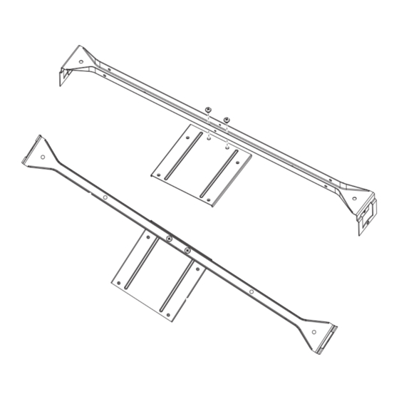
Statement 1072 Items Shipped with your Router Unpack the box and verify that all items listed on the invoice were shipped with the Cisco 812 ISR. The following items are shipped with your router: AC power adapter •... - Page 3 Installing the Cisco 810 ISR Figure 2-1 10-24 Screws 10-24 screws Box hanger Shelf bracket (PID 700-39491-01) Install the PoE+ splitter into the mounting plate with four 6-32 screws. (See Figure 2-2.) Step 2 Cisco Integrated Services Router Hardware Installation Guide...
- Page 4 Slide the power cord lock forward so that it captures the overmold and is fully seated. Figure 2-3 Placement of the Power Cord Lock onto the Power Cord Power cord connector Power cord lock Cisco Integrated Services Router Hardware Installation Guide...
- Page 5 Remove one ceiling tile to gain access. Step 7 Install the pre-assembled rail with PoE+ splitter into the T-rail. Push down the box hanger mounting clips Step 8 to lock into the T-rail as shown in Figure 2-5. Cisco Integrated Services Router Hardware Installation Guide...
-
Page 6: Installing The Sim Card
Place the router on a sturdy solid surface and orient the SIM access panel up to gain access. Ensure that Step 2 any installed antennas are oriented appropriately to avoid damage. Remove the SIM access panel being held in place by four 6-32 screws. (See Figure 2-6). Step 3 Cisco Integrated Services Router Hardware Installation Guide... - Page 7 Reinstall the same 6-32 flat head screws using a screw driver to secure the access panel back in place. Step 5 Figure 2-7 shows the SIM card installed and the SIM access panel closed. Cisco Integrated Services Router Hardware Installation Guide...
-
Page 8: Installing The 3G Antenna
Installing the Cisco 810 ISR Figure 2-7 SIM Access Panel Installing the 3G Antenna Install the antenna before you mount the Cisco 812 ISR. Note Warning Do not locate the antenna near overhead power lines or other electric light or power circuits, or where it can come into contact with such circuits. -
Page 9: Mounting The Cisco 812 Isr
Mounting the Cisco 812 ISR This section describes the steps in mounting the Cisco 812 ISR in several configurations, including on a suspended ceiling, on a hard ceiling or wall, and on an electrical or network box. This section contains... - Page 10 • Mounting Hardware Mounting hardware for the Cisco 812 ISR consists of brackets, which connect to the bottom of the router, and ceiling grid clips, which connect the bracket to a suspended ceiling. The bracket that you need depends on the mounting location for the router. The ceiling grid clip that you need depends on the type of suspended ceiling where you need to install the router.
- Page 11 Installing the Router Installing the Cisco 810 ISR Figure 2-10 Universal Bracket Installed on the Cisco 812 ISR Universal bracket Ceiling Grip Clips Use a ceiling grid clip to mount the router on a suspended ceiling. The ceiling grid clip that you need depends on the ceiling tiles on your ceiling.
- Page 12 Figure 2-12 shows the three types of ceiling rails: T-rail, channel, and beam. Figure 2-13 shows the Cisco Access Point installed with mounting bracket, ceiling grid clip, and adapter clips. Cisco Integrated Services Router Hardware Installation Guide 2-12...
- Page 13 Mounting the Cisco 812 ISR Below a Suspended Ceiling The recommended power option for the Cisco 812 ISR, when mounted below a suspended ceiling, is the Cisco C810-POE-SPL (PoE+ splitter) with the use of the supplied 1.3 meter power cable and Cat5 cable (Plenum rated).
- Page 14 Gently slide the router onto the mounting bracket until it clicks into place. Figure 2-14 shows the Step 12 Cisco 812 ISR mounted on a T-rail ceiling rail using a ceiling grid clip. Cisco Integrated Services Router Hardware Installation Guide 2-14...
- Page 15 Mounting the Cisco 812 ISR on a Hard Ceiling or a Wall This procedure describes the steps required to mount the Cisco 812 ISR on a ceiling constructed of 3/4-inch (19.05 mm) or thicker plywood using #8 fasteners using the universal mounting bracket (C810-BR-CM).
- Page 16 The pilot hole size varies according to the material and thickness you are fastening. It is recommended Note to test the material to determine the ideal hole size for your mounting application. Cisco Integrated Services Router Hardware Installation Guide 2-16...
- Page 17 Mounting the Cisco 812 ISR to a Network or Electrical Box To mount the Cisco 812 ISR to a network box or an electrical box, perform these steps: Position the universal mounting bracket (C810-BR-CM) over the existing network or electrical box and Step 1 align the bracket mounting holes with the box holes.
-
Page 18: Grounding The Cisco 812 Isr
Step 9 Grounding the Cisco 812 ISR Grounding is not always required for indoor installations because the Cisco 812 ISR is classified as a low-voltage device and does not contain internal power supplies. However, it is recommended that you check your local and national electrical codes to see if grounding is a requirement. If grounding is required in your area or you wish to ground your router, perform the following steps: Use copper conductors only. - Page 19 Connect the ring lug to the router grounding point and reinstall the same 6-32 screw. Step 7 Installing the Cisco 819 ISR This section describes the equipment and the procedures for successfully installing the Cisco 819 ISR and contains the following sections: Equipment, Tools, and Connections, page 2-20 •...
- Page 20 Statement 1078 Equipment, Tools, and Connections This section describes the equipment, tools, and connections necessary for installing your Cisco 819 ISR. It contains the following topics: Items Shipped with your Router, page 2-21 •...
- Page 21 Ethernet Devices, page 2-22 • Items Shipped with your Router Unpack the box and verify that all items listed on the invoice were shipped with the Cisco 819 ISR. The following items are shipped with your router: AC power supply (default) •...
- Page 22 If you plan to connect a modem, provide the modem and modem cable. Installing the Router This section describes how to install the Cisco 819 ISR. These routers can be installed on a table top or other flat horizontal surface mounted on a wall or DIN rail.
- Page 23 Caution Warning Hot surface. Statement 1079 To access the SIM card in the Cisco 819 ISR, follow these steps: Power off the router and disconnect the power cable from the power source. Step 1 Place the router on its side and ensure that any installed antennas are carefully oriented.
- Page 24 To open the SIM socket cover, slide the cover in the direction of the open arrow. (See Figure 2-19.) Step 4 Figure 2-19 Opening the SIM Socket Cover Gently lift the cover on its hinges. (See Figure 2-20.) Step 5 Cisco Integrated Services Router Hardware Installation Guide 2-24...
- Page 25 Slide the SIM card into the slot in the cover. Gently push down the cover to close. The SIM card will Step 6 come in contact with the metal contacts in the socket. (See Figure 2-21.) Cisco Integrated Services Router Hardware Installation Guide 2-25...
- Page 26 Installing the Cisco 810 ISR Figure 2-21 Sliding the SIM Card into the Slot To lock the cover, slide it in the direction of the lock arrow. (See Figure 2-22.) Step 7 Cisco Integrated Services Router Hardware Installation Guide 2-26...
- Page 27 Replace the panel and the screws. Step 8 Installing Antennas Before you install the Cisco 819 ISR on a table, wall, or DIN rail, install the antennas on the front panel. Note It is difficult to install the antennas after the router is installed.
- Page 28 WiFi antennas should be generally perpendicular to each other to achieve best coverage. Note Figure 2-24 Cisco WiFi Antenna Assembly 3G/4G Dipole External Antenna RP-TNC Connector WiFi 2.4/5 Ghz Dipole External Antenna Cisco Integrated Services Router Hardware Installation Guide 2-28...
- Page 29 2-33. Mounting on a Wall The Cisco 819 ISR has mounting holes on the bottom of the chassis for mounting the unit on a wall or other vertical surface. The attachment hardware is provided. When choosing a location for wall-mounting the router, consider cable limitations and wall structure.
- Page 30 Installing a DIN Rail You can use either the 7.5-mm or the 15-mm thick DIN rail for the Cisco 819 ISR. Secure the DIN rail to the mounting surface approximately every 7.8 inches (200 mm) and use end-anchors appropriately.
- Page 31 Installing the Router Installing the Cisco 810 ISR To attach the Cisco 819 ISR to a 35-mm wide DIN rail, follow these steps. Attach the DIN rail to the back of the router using the three screws provided. (See Figure 2-27.)
- Page 32 Chapter 2 Installing the Router Installing the Cisco 810 ISR Figure 2-29 Cisco 819 ISR Installed with the DIN Rail Cisco Integrated Services Router Hardware Installation Guide 2-32...
- Page 33 Mount can be utilized to mount the router flat against the DIN rail. It can also be configured in three different ways to allow router cabling to exit from the bottom, right or left. Figure 2-30 Configurable Low Profile DIN Mount standard configuration Cisco Integrated Services Router Hardware Installation Guide 2-33...
- Page 34 Remove the DIN Rail Latch Springs (Item 4) Identify the desired mounting configuration and replace the latch assemblies in slots with the matching labels, using the reverse order of steps 1 through 3. Cisco Integrated Services Router Hardware Installation Guide 2-34...
- Page 35 Locate the “L” bracket that came with the mount, and screw the bracket to the router with the other 6-32 x .375 Philips/Pan Head screw and locking washer (Cisco 48-0422-01). Now screw the bracket to the mount with the shorter, supplied, 6-32 x .25 Philips/Pan Head screw and locking washer (Cisco 48-0421-01).
- Page 36 If you are using this router in a vehicle, attach the ring terminal to the chassis using one of the screws Step 7 provided and the green or green and yellow striped wire. Connect the other end of the wire to the vehicle ground. Cisco Integrated Services Router Hardware Installation Guide 2-36...
- Page 37 Installing the Power Cord Retention Lock The Cisco 819 ISRs have a power cord retention mechanism as an accessory. It locks the power cord to the router so when a user accidentally pulls out the power cord, the power cord will not come out from the router.
- Page 38 Installing the Power Switch Lock The Cisco 819 ISRs have a power switch lock as an accessory. The power switch lock prevents unauthorized access to a tampered proof router (for example, router in a bus). For the complete list of...
- Page 39 Installing the Cisco 810 ISR Figure 2-38 Installing Power Switch Lock Ring terminal Power switch lock Power switch lock washer Pan-head screw Power switch lock standoff Figure 2-39 Power Switch Lock Installed Cisco Integrated Services Router Hardware Installation Guide 2-39...
-
Page 40: Mounting The Dc Power Supply
Statement 378 The Cisco 800 ISR DC power supply may be mounted to a wall using four #6 pan- or round-head wood screws for the mounting holes on the supply. - Page 41 IP 41 compliance. Installing the Cisco 860, 880, 890 ISR This section describes the equipment and the procedures for successfully installing the Cisco 860 series, 880 series, and 890 series ISRs, and contains the following sections: Equipment, Tools, and Connections, page 2-42 •...
-
Page 42: Additional Items
AC power supply cable with cable retention clip Cisco Configuration Professional (Cisco CP) CD 1. By default, no cables are shipped with Cisco 860VAE models unless requested through the dynamic configuration tool. 2. DSL = digital subscriber line. 3. Shipped with Cisco 867 models only. -
Page 43: Ethernet Devices
Installing the Cisco 860, 880, and 890 Series Routers This section describes how to install the Cisco 860 series, 880 series, and 890 series ISRs. These routers can either be installed on a table top or other flat horizontal surface or be mounted on a wall. The Cisco 890 series ISRs may be mounted in a rack. -
Page 44: Warnings
Keep at least 1 inch (2.5 cm) of clear space beside the cooling inlet and exhaust vents. Connect the chassis to a reliable earth ground. For the chassis ground connection procedures, see the “Installing Cisco 890 Series in a Rack” section on page 2-56. -
Page 45: Mounting On A Wall
Note Mounting on a Wall The Cisco 860 series, 880 series, and 890 series ISRs have mounting holes on the bottom of the chassis for mounting the unit on a wall or other vertical surface. The mounting holes are bidirectional. You can hang the router with the front bezel facing upward or downward. - Page 46 Chapter 2 Installing the Router Installing the Cisco 860, 880, 890 ISR Figure 2-41 Wall-mount Holes on the Underside of the Router 8.200 in. 3.673 in. 5.961 in. Wall-mount holes Insert the screws, with anchors, into the wall. Leave 1/8 inch (0.32 cm) between the screw head and the Step 2 wall.
-
Page 47: Installing The Router Ground Connection
1/8 in. (0.32 cm) Connect the chassis to a reliable earth ground. For the chassis ground connection procedures, see the Step 4 “Installing Cisco 890 Series in a Rack” section on page 2-56. Installing the Router Ground Connection The router must be connected to a reliable earth ground. Install the ground wire in accordance with local electrical safety standards. -
Page 48: Installing The Fips Cover
Chapter 2 Installing the Router Installing the Cisco 860, 880, 890 ISR To install the ground connection, follow these steps: Strip one end of the ground wire to the length required for the ground lug or terminal. Step 1 Crimp the ground wire to the ground lug or ring terminal, using the wire crimper. - Page 49 Chapter 2 Installing the Router Installing the Cisco 860, 880, 890 ISR Remove the four mounting screws of the top cover. Step 1 Cisco Integrated Services Router Hardware Installation Guide 2-49...
- Page 50 Chapter 2 Installing the Router Installing the Cisco 860, 880, 890 ISR Install the left-side FIPS cover, as shown in detail A. Step 2 Detail A Adapter Plate Rotate and bring into the close position to hinge to the correct hexagon.
- Page 51 Chapter 2 Installing the Router Installing the Cisco 860, 880, 890 ISR Secure the FIPS cover with two mounting screws. Step 5 Install the right-side FIPS cover the same way as the left-side FIPS cover. Step 6 View after both covers are installed.
-
Page 52: Installing Antennas For Cisco 890 Series
All wireless LAN products in the 5.2/5.3GHz band cannot be used outdoors. Use the product only Warning indoors. Statement 372 Before you install the Cisco 890 series wireless router on a table, wall, or rack, connect the antennas to Note the back panel. It is difficult to attach the antennas after the router is installed. - Page 53 Chapter 2 Installing the Router Installing the Cisco 860, 880, 890 ISR To attach the radio antennas to your wireless router, follow these steps: Manually screw the antennas tight to the RP-TNC connectors on the back of the router. Step 1...
- Page 54 Chapter 2 Installing the Router Installing the Cisco 860, 880, 890 ISR Figure 2-45 Antennas Oriented Vertically Up Cisco Integrated Services Router Hardware Installation Guide 2-54...
- Page 55 Chapter 2 Installing the Router Installing the Cisco 860, 880, 890 ISR Figure 2-46 Antennas Oriented Vertically Down Cisco Integrated Services Router Hardware Installation Guide 2-55...
-
Page 56: Installing Cisco 890 Series In A Rack
Figure 2-47 Screw Locations Screws Using the screws provided, attach the rack-mount brackets to the Cisco 890 series ISR chassis, as shown Step 2 Figure 2-48. Use two screws on each side. Use a number 2 Phillips screwdriver to install the bracket screws on both sides of the chassis. - Page 57 Statement 1006 Using two screws for each side (supplied with the rack), attach the Cisco 890 series ISR with rack-mount Step 3 brackets to a 19-inch rack. Start with the lower pair of screws first, resting the brackets on the lower screws while you insert the upper pair of screws.
- Page 58 C881G-B/S/V-K9 ISR because it does not have a slot for adding a SIM card. These are CDMA/EV-DO based routers and do not require a SIM card. Installing Antennas For instructions on installing the antennas for the Cisco 881 routers, please refer to the “Installing Antennas” section on page 2-58.
- Page 59 Chapter 2 Installing the Router Installing the Cisco 860, 880, 890 ISR Figure 49 SIM Card Installation Cisco Integrated Services Router Hardware Installation Guide 2-59...
- Page 60 C881GW+7-A-K9, C881GW+7-E-K9, C887VAGW+7-A-K9, and C887VAGW+7-E-K9 ISRs, follow the instructions in the “Installing the Cisco 860, 880, and 890 Series Routers” section on page 2-43. However, the instructions for connecting the 3G card in the hardware installation guide do not apply because these ISRs do not have a slot for adding a 3G card.