Table of Contents
Advertisement
Advertisement
Table of Contents

Related Manuals for Siemens micromaster 410


Summary of Contents for Siemens micromaster 410
- Page 2 MICROMASTER 410 Documentation Getting Started Guide Is for quick commissioning. Operating Instructions Gives information about features of the MM410, Installation, Commissioning, Control modes, System Parameter structure, Troubleshooting, Specifications and available options of the MM410. Parameter List The Parameter List contains the description of all Parameters structured in functional order and a detailed description.
-
Page 3: Commissioning
Overview Installation MICROMASTER 410 Commissioning Using the MICROMASTER 410 Operating Instructions System Parameters User Documentation Troubleshooting MICROMASTER 410 Specifications Available options Electro-Magnetic Compatibility Valid for Issue 04/02 Converter Type Software version Appendices MICROMASTER 410 V1.6 Index Issue 04/02... - Page 4 Further information can be obtained from Internet website: http://www.siemens.de/micromaster Approved Siemens Quality for Software and Training Other functions not described in this document may be is to DIN ISO 9001, Reg. No. 2160-01 available. However, this fact shall not constitute an...
- Page 6 Earth voltage. This connection is normally used to ground the motor. Use for intended purpose only The equipment may be used only for the application stated in the manual and only in conjunction with devices and components recommended and authorized by Siemens. MICROMASTER 410 Operating Instructions 6SE6400-5EA00-0BP0...
- Page 7 Please read the information carefully, since it is provided for your personal safety and will also help prolong the service life of your MICROMASTER 410 Inverter and the equipment you connect to it. General WARNING ♦...
- Page 8 The connection of power, motor and control cables to the inverter must be carried out as shown in Figure 2-10 on page 30, to prevent inductive and capacitive interference from affecting the correct functioning of the inverter. MICROMASTER 410 Operating Instructions 6SE6400-5EA00-0BP0...
- Page 9 Siemens or by qualified personnel who are thoroughly acquainted with all the warnings and operating procedures contained in this manual. ♦ ♦ ♦ ♦ Any defective parts or components must be replaced using genuine Siemens authorised parts. ♦...
- Page 10 Safety Instructions Issue 04/02 MICROMASTER 410 Operating Instructions 6SE6400-5EA00-0BP0...
-
Page 11: Table Of Contents
Issue 04/02 Table of Contents Table of Contents Overview ........................ 15 The MICROMASTER 410 ..................15 Features ........................15 Installation ......................17 General........................18 Power Losses......................19 Ambient operating conditions.................. 19 Harmonic Currents ....................21 Derating with Pulse Frequencies ................21 Overvoltage and Trip Levels ................... - Page 12 Variant Independent Options .................. 67 Variant Dependent Options..................67 Electro-Magnetic Compatibility (EMC) ..............69 Electro-Magnetic Compatibility (EMC) ..............69 Appendices..........................75 Fitting the Operator Panel ..................75 Applicable Standards ....................76 List of Abbreviations ....................77 Index ..........................78 MICROMASTER 410 Operating Instructions 6SE6400-5EA00-0BP0...
- Page 13 Figure 2-10 Wiring Guidelines to Minimize the Effects of EMI ..............30 Figure 3-1 Inverter block diagram ......................32 Figure 3-2 Operator Panel for the MICROMASTER 410 Inverter ............33 Figure 3-3 Basic operation ........................34 Figure 3-4 Changing the Line Supply Frequency...................35 Figure 3-5 Buttons on the Operator Panel .....................37...
- Page 14 Table of Contents Issue 04/02 MICROMASTER 410 Operating Instructions 6SE6400-5EA00-0BP0...
-
Page 15: Overview
Comprehensive protective functions provide excellent inverter and motor protection. The MICROMASTER 410 with its default factory settings is ideal for a large range of simple motor control applications. The MICROMASTER 410 can be used in both 'stand-alone' applications as well as being integrated into 'Automation Systems'. - Page 16 Ø Automatic restart after a mains failure Ø Start-on-the-fly Protection Characteristics Ø Overvoltage/undervoltage protection Ø Overtemperature protection for the inverter Ø Ground fault protection Ø Short-circuit protection Ø I t thermal motor protection Ø Motor stall prevention MICROMASTER 410 Operating Instructions 6SE6400-5EA00-0BP0...
-
Page 17: Installation
The connection of power, motor and control cables to the inverter must be carried out as shown in Figure 2-10 on page 30, to prevent inductive and capacitive interference from affecting the correct functioning of the inverter. MICROMASTER 410 Operating Instructions 6SE6400-5EA00-0BP0... -
Page 18: General
XAM214-123456 Character 4 is the month (1-9 =Jan-Sep, O =Oct, N =Nov, D =Dec) XAM214-123456 Characters 5-6 are the day of the month XAM214-123456 Character 7 is a seperator XAM214-123456 Characters 8-13 are the sequential serial number 1-999999 MICROMASTER 410 Operating Instructions 6SE6400-5EA00-0BP0... -
Page 19: Power Losses
Issue 04/02 2 Installation Power Losses Figure 2-2 shows the power loss for 230V MM410 Power losses the MICROMASTER 410 Inverter. The graph can be used to read the loss at full load of a particular variant. 0,12 0,25 0,37... - Page 20 23. Ensure that the inverter’s air vents are not obstructed. Allow 100 mm clearance above and below the inverter. A clearance of 30 mm on both sides of the inverter is also required. MICROMASTER 410 Operating Instructions 6SE6400-5EA00-0BP0...
-
Page 21: Harmonic Currents
4 kHz 6 kHz 8 kHz 10 kHz 12 kHz 14 kHz 16 kHz 0.12 0.25 0.37 0.55 (115V,50°C) 0.55 (115V,40°C) 0.75 0.75 (40º C) All currents are rated at 50 ºC unless otherwise stated MICROMASTER 410 Operating Instructions 6SE6400-5EA00-0BP0... -
Page 22: Overvoltage And Trip Levels
The mains input, DC and motor terminals, can carry dangerous voltages even if the inverter is inoperative; wait 5 minutes to allow the unit to discharge after switching off before carrying out any installation work. Figure 2-4 Dimensions of the MICROMASTER 410 MICROMASTER 410 Operating Instructions 6SE6400-5EA00-0BP0... -
Page 23: Figure 2-5 Clearance Distances For Mounting The Inverter
(5.91”) (2.72”) (5.43”) Connecting to DIN rail** Not supplied with the inverter. ** The DIN rail mounting kit is an optional extra which must be ordered separately. For details see Section 2.7.2 on page 25. MICROMASTER 410 Operating Instructions 6SE6400-5EA00-0BP0... -
Page 24: Figure 2-6 Mounting Brackets
2.7.1 Mounting Brackets The MICROMASTER 410 can be mounted using mounting brackets, which are slotted into the heatsink at the rear of the inverter for normal mounting position (see Figure 2-6 A. For side mounting of the inverter the brackets are slotted into the heatsink as shown in Figure 2-6 B. - Page 25 Drawing E. 2. The inverter can now be pushed and locked onto the DIN rail. The inverter can be removed from the DIN rail by pulling the retaining clip in a downward direction. MICROMASTER 410 Operating Instructions 6SE6400-5EA00-0BP0...
-
Page 26: Electrical Installation
On ungrounded supplies, it will be necessary to cut the ‘Y’ capacitor link from the inside of the unit. The procedure for removing this capacitor is described on page 28 (Figure 2-7) of this manual. MICROMASTER 410 Operating Instructions 6SE6400-5EA00-0BP0... - Page 27 For 115 V units use class 1 75 °C copper wire only. For tightening torque see Table 7-2 on page 64. ♦ To tighten up the power terminal screws use a 4 - 5 mm cross-tip screwdriver. MICROMASTER 410 Operating Instructions 6SE6400-5EA00-0BP0...
-
Page 28: Figure 2-7 Position Of 'Y' Capacitor Link
Figure 2-8 MICROMASTER 410 is in regenerative mode. Connection Terminals MICROMASTER 410 Operating Instructions 6SE6400-5EA00-0BP0... -
Page 29: Figure 2-9 Motor And Power Connections
Varistor suppressors are also effective. This is important when the contactors are controlled from the inverter relay. Ø Use screened or armored cables for the motor connections and ground the screen at both ends using the cable clamps. MICROMASTER 410 Operating Instructions 6SE6400-5EA00-0BP0... -
Page 30: Figure 2-10 Wiring Guidelines To Minimize The Effects Of Emi
Use suitable clips to fix motor and control cable screens securely to metal back plate Mains power cable Metal mounting brackets Line commutating Choke Control cable Figure 2-10 Wiring Guidelines to Minimize the Effects of EMI MICROMASTER 410 Operating Instructions 6SE6400-5EA00-0BP0... -
Page 31: Commissioning
♦ ♦ ♦ ♦ This equipment must not be used as an ‘emergency stop mechanism’ (see EN 60204, 9.2.5.4) CAUTION Only qualified personnel may enter settings in the control panels. Particular attention must be paid to safety precautions and warnings at all times. MICROMASTER 410 Operating Instructions 6SE6400-5EA00-0BP0... -
Page 32: Block Diagram
3 Commissioning Issue 04/02 Block Diagram Figure 3-1 Inverter block diagram RS485 USS-protocol MICROMASTER 410 Operating Instructions 6SE6400-5EA00-0BP0... -
Page 33: Commission Modes
Issue 04/02 3 Commissioning Commission Modes The MICROMASTER 410 is supplied with default parameter settings cover the following: Ø The motor rating data; voltage, current and frequency data is keyed into the inverter to ensure that the motor is compatible with the inverter. (A standard Siemens motor is recommended). -
Page 34: Figure 3-3 Basic Operation
Ø Fault Acknowledgement (DIN3 via external switch) Controlling the speed of the motor is accomplished by connecting the analog inputs as shown in the Figure 3-3 (Switches and potentiometers are not supplied with the inverter). RS485 USS-protocol Figure 3-3 Basic operation MICROMASTER 410 Operating Instructions 6SE6400-5EA00-0BP0... -
Page 35: Figure 3-4 Changing The Line Supply Frequency
For a detailed description of the parameter, see the Parameter List. NOTE We recommend the commissioning according this scheme. Nevertheless an expert user is allowed to do the commissioning without the filter functions of P0004. MICROMASTER 410 Operating Instructions 6SE6400-5EA00-0BP0... -
Page 36: Table 3-2 Default Settings For Operation Using The Op
The Operator Panel (OP) provides access to the inverter parameters and enables the user to customize the settings of your MICROMASTER 410. The OP can be used to configure several MICROMASTER 410 Inverters. This is accomplished by using the OP to set the required parameters and once the process is complete, then the OP can be removed. -
Page 37: Figure 3-5 Buttons On The Operator Panel
Access Pressing this button allows access to the parameters. parameters Increase Pressing this button increases the displayed value. value Decrease Pressing this button decreases the displayed value. value Figure 3-5 Buttons on the Operator Panel MICROMASTER 410 Operating Instructions 6SE6400-5EA00-0BP0... -
Page 38: Figure 3-6 Changing Parameters Via The Op
Press to confirm and store the value Press until r0000 is displayed Press to return the display to the standard drive display (as defined by the customer) Figure 3-6 Changing parameters via the OP MICROMASTER 410 Operating Instructions 6SE6400-5EA00-0BP0... - Page 39 At the end of the quick commissioning sequence, P3900 should be selected, which, when set to 1, will carry out the necessary motor calculations and clear all other parameters (not included in P0010=1) to the default settings. This will only happen in the Quick Commissioning mode. MICROMASTER 410 Operating Instructions 6SE6400-5EA00-0BP0...
- Page 40 I/O reset. 1) Motor related parameters – please refer to motor rating plate. 2) Denotes parameters that contain more detailed lists of possible settings for use in specific applications. Please refer to the Parameter List MICROMASTER 410 Operating Instructions 6SE6400-5EA00-0BP0...
-
Page 41: Figure 3-7 Typical Motor Rating Plate Example
To reset all parameters to the factory default settings; the following parameters should be set as follows (the operator panel option is required): 1. Set P0010 = 30 2. Set P0970 = 1 NOTE The reset process can take up to 3 minutes to complete. MICROMASTER 410 Operating Instructions 6SE6400-5EA00-0BP0... -
Page 42: General Operation
3. The inverter is programmed at the factory for standard applications on Siemens four-pole standard motors that have the same power rating as the inverters. When using other motors it is necessary to enter the specifications from the motor's rating plate. -
Page 43: Figure 3-8 Motor Overload Ptc Connection
PTC temperature sensor must be fitted to the motor and connected to the inverter control terminals as shown in Figure 3-8. Figure 3-8 Motor Overload PTC Connection NOTE To enable the trip function, set parameter P0701, P0702 or P0703 = 29. MICROMASTER 410 Operating Instructions 6SE6400-5EA00-0BP0... - Page 44 3 Commissioning Issue 04/02 MICROMASTER 410 Operating Instructions 6SE6400-5EA00-0BP0...
-
Page 45: Using The Micromaster 410
Issue 04/02 4 Using the MICROMASTER 410 Using the MICROMASTER 410 WARNING ♦ ♦ ♦ ♦ When operating electrical devices, it is impossible to avoid applying hazardous voltages to certain parts of the equipment. ♦ ♦ ♦ ♦ Emergency Stop facilities according to EN 60204 IEC 204 (VDE 0113) must remain operative in all operating modes of the control equipment. -
Page 46: Command Sources (P0700)
4 Using the MICROMASTER 410 Issue 04/02 Command Sources (P0700) NOTICE The ramp times and ramp-smoothing functions also affect how the motor starts and stops. For details of these functions, please refer to parameters P1120, P1121, P1130 – P1134 in the Parameter List. -
Page 47: Compound Braking
Issue 04/02 4 Using the MICROMASTER 410 4.3.2 OFF2 This command causes the motor to coast to a standstill (pulses disabled). NOTICE The OFF2 command can have one or more sources. By default the OFF2 command is set to Operator Panel. This source still exists even if other sources are defined by one of the following parameters, P0700 to P0704 inclusive. -
Page 48: Control Modes (P1300)
Issue 04/02 Control Modes (P1300) The various modes of operation of the MICROMASTER 410 control the relation- ship between the speed of the motor and the voltage supplied by the inverter. A summary of the control modes available are listed below: Ø... -
Page 49: System Parameters
Standard and Extended levels are sufficient. The number of parameters that appear within each functional group (selected by P0004) depends on the access level set in parameter P0003. For further details regarding parameters, see the Parameter List. MICROMASTER 410 Operating Instructions 6SE6400-5EA00-0BP0... -
Page 50: Parameter Overview
Communication P0004 = 7 P0004 = 13 Commands and Motor Control Digtal I/O P0004 = 12 P0004 = 8 Drive Features Analogue I/O P0004 = 10 Setpoint Channel & Ramp Generator Figure 5-1 Parameter Overview MICROMASTER 410 Operating Instructions 6SE6400-5EA00-0BP0... -
Page 51: Parameter List (Short Form)
ParText Default r0018 Firmware version r0026 CO: Act. DC-link voltage r0206 Rated inverter power [kW] / [hp] r0207 Rated inverter current r0209 Maximum inverter current P0210 Supply voltage P0290 Inverter overload reaction P1800 Pulse frequency MICROMASTER 410 Operating Instructions 6SE6400-5EA00-0BP0... - Page 52 CO/BO: Binary input values P0724 Debounce time for digital inputs P0731 BI: Function of digital output 1 52:3 r0747 CO/BO: State of digital outputs P0748 Invert digital outputs P0810 BI: CDS bit 0 (Local / Remote) MICROMASTER 410 Operating Instructions 6SE6400-5EA00-0BP0...
- Page 53 Ramp-up initial rounding time 0.00 P1131 Ramp-up final rounding time 0.00 P1132 Ramp-down initial rounding time 0.00 P1133 Ramp-down final rounding time 0.00 P1134 Rounding type P1135 OFF3 ramp-down time 5.00 r1170 CO: Frequency setpoint after RFG MICROMASTER 410 Operating Instructions 6SE6400-5EA00-0BP0...
- Page 54 0.00 P1323 Programmable V/f volt. coord. 2 P1324 Programmable V/f freq. coord. 3 0.00 P1325 Programmable V/f volt. coord. 3 P1333 Start frequency for FCC 10.0 P1335 Slip compensation P1340 Imax controller prop. gain 0.000 MICROMASTER 410 Operating Instructions 6SE6400-5EA00-0BP0...
- Page 55 BO: CtrlWrd2 from COM link (USS) Alarms, Faults and Monitoring (P0004 = 21) ParNr ParText Default P0952 Total number of faults r0947[8] Last fault code r2110[4] Warning number r2114[2] Run time counter P2167 Switch-off frequency f_off 1.00 MICROMASTER 410 Operating Instructions 6SE6400-5EA00-0BP0...
- Page 56 5 System Parameters Issue 04/02 MICROMASTER 410 Operating Instructions 6SE6400-5EA00-0BP0...
-
Page 57: Troubleshooting
Troubleshooting WARNING ♦ ♦ ♦ ♦ Repairs on equipment may only be carried out by Siemens Service, by repair centers authorized by Siemens or by qualified personnel who are thoroughly acquainted with all the warnings and operating procedures contained in this manual. -
Page 58: Fault Messages
Read or write failure while saving Factory Reset and new parameterization OFF2 Parameter non-volatile parameter. Change drive EEPROM Fault F0052 Read failure for power stack Change drive OFF2 power stack information or invalid data. Fault MICROMASTER 410 Operating Instructions 6SE6400-5EA00-0BP0... - Page 59 OFF2 Stack Ø Replace drive if fault is not corrected. Overflow Ø Drive may run but some features will not work F0450 Selftest failed OFF2 BIST Tests properly. Failure Ø Replace drive. (Service Mode Only) MICROMASTER 410 Operating Instructions 6SE6400-5EA00-0BP0...
-
Page 60: Alarms
Occurs at very high load inertias, when ramping down. A0911 Vdc max controller is active; so ramp- Check the inverter input voltage (P0210) Vdc-max down times will be increased controller automatically to keep DC-link voltage active (r0026) within limits MICROMASTER 410 Operating Instructions 6SE6400-5EA00-0BP0... - Page 61 No Load is applied to the inverter. Check that a load has been applied to the No load inverter. As a result, some functions may not applied to work as under normal load conditions. inverter MICROMASTER 410 Operating Instructions 6SE6400-5EA00-0BP0...
- Page 62 6 Troubleshooting Issue 04/02 MICROMASTER 410 Operating Instructions 6SE6400-5EA00-0BP0...
-
Page 63: Micromaster 410 Specifications
Issue 04/02 7 MICROMASTER 410 Specifications MICROMASTER 410 Specifications Table 7-1 MICROMASTER 410 Performance Ratings Feature Specification Mains Operating Voltage & 100 to 120 V ± 10% 1AC 0.12 kW – 0.55 kW Power Ranges 200 to 240 V ± 10% 1AC 0.12 kW –... -
Page 64: Table 7-2 Terminal Torques - Field Wiring Connectors
7 MICROMASTER 410 Specifications Issue 04/02 Table 7-2 Terminal Torques – Field Wiring Connectors Motorside PE All other terminals terminal [Nm] Tightening Torque [lbf.in] Table 7-3 MICROMASTER 410 Specifications Input voltage range 1 AC 200 V – 240 V, ± 10 % (with built in Class B Filter) Order No. - Page 65 Issue 04/02 7 MICROMASTER 410 Specifications Input voltage range 1 AC 200 V – 240 V, ± 10 % (Unfiltered) Order No. 6SE6410- 2UB11 2UB12 2UB13 2UB15 2UB17 -2AA0 -5AA0 -7AA0 -5BA0 -5BA0 [kW] 0.12 0.25 0.37 0.55 0.75 Motor Output Rating [hp] 0.16...
- Page 66 7 MICROMASTER 410 Specifications Issue 04/02 MICROMASTER 410 Operating Instructions 6SE6400-5EA00-0BP0...
-
Page 67: Options
Options The following accessories are available as options for your MICROMASTER MM410 Inverter. For more details please refer to the catalogue or contact your local Siemens sales office if you require assistance. Variant Independent Options Ø Operator Panel (OP) Ø DIN Rail Mounting Kit Ø... - Page 68 8 Options Issue 04/02 MICROMASTER 410 Operating Instructions 6SE6400-5EA00-0BP0...
-
Page 69: Electro-Magnetic Compatibility (Emc)
European government organization. This approach allows the use of standards that are still in preparation. NOTE However, MICROMASTER 410 is designed to be used only by professional endusers with EMC knowledge. It is not designed for users having no EMC knowledge. - Page 70 EN 61000-3-2 "Limits for harmonic current emissions (equipment input ≤ 16 A per phase)". All Siemens variable speed drives of the MICROMASTER, MIDIMASTER, MICROMASTER Eco and COMBIMASTER ranges, which are classified as "Professional Equipment" within the terms of the standard, fulfill the requirements of the standard.
-
Page 71: Table 9-1 Case 1 - General Industrial
8 kV air discharge Burst Interference EN 61000-4-4 2 kV power cables (Level 3), 2 kV control (Level 4) Radio Frequency Electromagnetic EN 61000-4-3 80-1000 MHz, 10 V/m, 80% AM, Field, amplitude modulated power and signal lines MICROMASTER 410 Operating Instructions 6SE6400-5EA00-0BP0... -
Page 72: Table 9-3 Case 3 - Filtered For Residential, Commercial And Light Industry
If compliance with the product standard is required, filtered inverters ( as described under case 2) have to be installed. Case 2 – Filtered Industrial 6SE6410-2B***-**A0 All units with integral filters for screened motor cables up to 10 m (32,80 ft) [Class A] MICROMASTER 410 Operating Instructions 6SE6400-5EA00-0BP0... - Page 73 C2: Power Drive System (PDS) of rated voltage less than 1000V, which when used in the first environment is intended to be installed and commissioned only by a professional. MICROMASTER 410 Operating Instructions 6SE6400-5EA00-0BP0...
-
Page 75: Appendices
Issue 04/02 Fitting the Operator Panel Appendices Fitting the Operator Panel MICROMASTER 410 Operating Instructions 6SE6400-5EA00-0BP0... -
Page 76: B Applicable Standards
Underwriters Laboratories UL and CUL LISTED POWER CONVERSION EQUIPMENT 5B33 for use in a pollution degree 2 ISO 9001 Siemens plc operates a quality management system, which complies with the requirements of ISO 9001. Notice: Machinery Directive The devices are suitable for installation in machines. According to the machinery directive 89/392/EC the compliance requires a separate certificate of conformity. -
Page 77: C List Of Abbreviations
Fast Current Limitation IGBT Insulated Gate Bipolar Transistor Input and Output Liquid Crystal Display Light Emitting Diode Operator Panel Programmable Logic Controller Positive Temperature Coefficient RCCB Residual Current Circuit Breaker Residual Current Device Revolutions Per Minute MICROMASTER 410 Operating Instructions 6SE6400-5EA00-0BP0... -
Page 78: Index
Dimensions and Torques......23 Installation ..........17 after a period of storage .......18 DIN Rail Mounting........25 Installation and cooling......20 Drill pattern for MICROMASTER 410 ..22 Internet Home Address ......5 Inverter block diagram......32 Electrical Installation ........ 26 Electro-Magnetic Compatibility general ..........69 Linear V/f control ........48... - Page 79 Issue 04/02 Index MICROMASTER 410 Quick commissioning .......39 available options ........67 general ..........15 main characteristics ......15 Reset to Factory default ......41 performance characteristics ....16 Residual Current Device protection characteristics ..... 16 operation with ........27 specifications........63 Motor connections ........
- Page 80 Index Issue 04/02 MICROMASTER 410 Operating Instructions 6SE6400-5EA00-0BP0...
- Page 81 Suggestions and/or Corrections Suggestions Siemens AG Automation & Drives Group Corrections SD VM 4 P.O. Box 3269 For Publication/Manual: MICROMASTER 410 D-91050 Erlangen Federal Republic of Germany Email: Technical.documentation@con.siemens.co.uk User Documentation Operating Instructions From Order Number: Name: 6SE6400-5EA00-0BP0 Date of Issue: 04/02...
- Page 82 MICROMASTER 410 Operating Instructions 6SE6400-5EA00-0BP0...
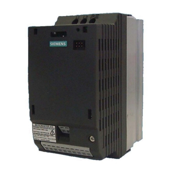
- Page 83 View of Units View of Unit Key: 1. Line Terminals 2. Status LED 3. Operator Panel Connector Standard Inverter 4. Control Terminals 5. Motor Terminals 6. DC+/DC- Terminals Inverter with Optional Operator Panel Fitted Connections & Terminals MICROMASTER 410 Operating Instructions 6SE6400-5EA00-0BP0...