
Related Manuals for Hach AMTAX sc


Summary of Contents for Hach AMTAX sc
- Page 1 DOC023.52.00025 AMTAX sc, AMTAX indoor sc USER MANUAL 04/2013, Edition 8A AMTAX sc, AMTAX indoor sc © HACH-LANGE GmbH, 2006–2010; 2012, 2013. All rights reserved. Printed in Germany. sd/sk...
-
Page 3: Table Of Contents
Table of Contents Section 1 Specifications ......................5 Section 2 General Information ....................9 2.1 Safety information ........................9 2.1.1 Use of hazard information ....................9 2.1.2 Precautionary labels ......................9 2.1.3 Change instrument labels ....................10 2.2 Product overview ........................10 Section 3 Installation ...................... - Page 4 Table of Contents 6.5 Replace the membrane cap, electrolyte and electrode ..............49 6.6 Validation (Analytical quality assurance) ..................52 6.7 Shut the analyzer down ......................54 6.7.1 Shut the analyzer down for an extended period ..............54 6.8 Modify from single channel to dual channel ................55 Section 7 Troubleshooting ....................57 7.1 Troubleshooting the controller ....................57 7.2 Troubleshooting the analyzer .....................57...
-
Page 5: Section 1 Specifications
Outputs Relay, current outputs, bus interface via sc1000 controller AMTAX sc: –20 to 45 °C (–4 to 113 °F); 95 % relative humidity, non-condensing Operating temperature AMTAX indoor sc: 5 to 40 °C (41 to 104 °F); 95 % relative humidity, non-condensing –20 to 60 °C (–4 to 140 °F);... -
Page 6: Specifications
Dimensions (Figure 1, page AMTAX sc: (W × H × D) 540 × 720 × 390 mm (21,25 × 28,35 × 15,35 in.) Figure 1, page AMTAX indoor sc: (W × H × D) 540 × 720 × 370 mm (21,25 × 28,35 × 14.5 in.) Data and power cable lengths 2 m (80 in.) (from edge of enclosure) - Page 7 Specifications Figure 1 Instrument dimensions AMTAX sc...
- Page 8 Specifications [1.57 in] 850 mm [33.15 in] 370 mm 540 mm [14.57 in] [21.26 in] 720 mm [28.35 in] Figure 2 Instrument dimensions AMTAX indoor sc...
-
Page 9: Section 2 General Information
Section 2 General Information 2.1 Safety information Please read this entire manual before unpacking, setting up or operating this equipment. Pay attention to all danger and caution statements. Failure to do so could result in serious injury to the operator or damage to the equipment. Make sure that the protection provided by this equipment is not impaired, do not use or install this equipment in any manner other than that specified in this manual. -
Page 10: Change Instrument Labels
(waste water, process water and surface water). The measured value is displayed in mg/L -N on the controller. The AMTAX sc must be used in combination with the sc1000 controller. The sc1000 controller is used to configure, power and output the measured values. -
Page 11: General Information
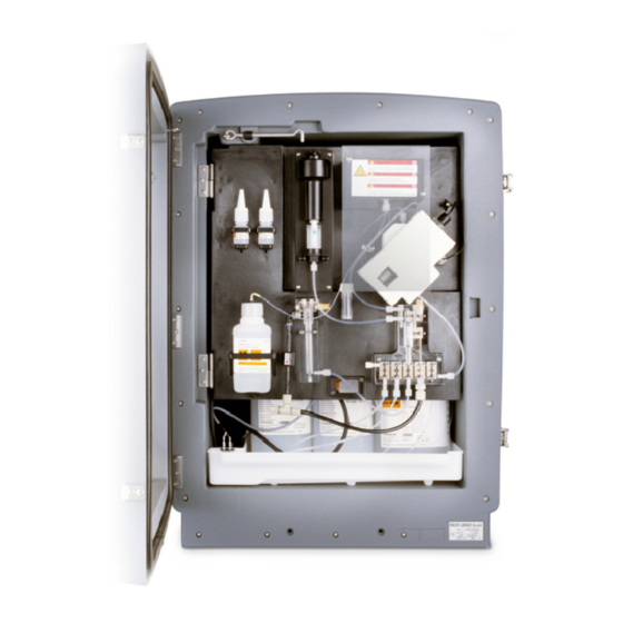
Dual channel operation is only possible with continuous sample preparation, e.g. FILTRAX or Ultrafiltration. Sample preparation and filtration must be provided before installing the analysis instrument. Figure 3 AMTAX sc enclosure LED for operating state. Refer to Door lock Rating plate with model number,... - Page 12 General Information...
-
Page 13: Section 3 Installation
23). 6. Mount the Filter Probe sc or Filtrax, if necessary. Refer to the appropriate manual for more information. 7. Connect the Filter Probe sc or Filtrax to the AMTAX sc, if necessary. Refer to section 3.5.3, page 26 for the Filter Probe sc. -
Page 14: Unpack The Instrument
FILTRAX or Ultrafiltration), plan where the instruments are to be installed and consider the length of the heated drain tubing (2 m). 3.3.1 Mount the instrument The AMTAX sc can be mounted in three different ways: • Wall Mount (section 3.3.1.1),... - Page 15 Installation 4. Attach the enclosure to the fastening bracket. 5. Attach the angle bracket on the enclosure to the wall. Figure 5 Bracket dimensions for wall mounting...
- Page 16 Installation Figure 6 Wall mounting the analyzer Socket head cap screw, M5 X 8 (2X) Screw, customer supplied Washer, M5 (4X) Socket head cap screw, M5 X 40 (2X) Angle bracket Fastening bracket...
-
Page 17: Initial Instrument Setup
2. Open the side latches and release the door catch. 3. Open the door and secure the door using the hook or completely remove the door. Figure 7 Open the enclosure AMTAX sc Latches Pocket for user manual Door hook... - Page 18 Installation Figure 8 Open the enclosure AMTAX indoor sc Latches Lock with key Door hook...
-
Page 19: Remove The Shipping Transport Locks
Installation 3.4.2 Remove the shipping transport locks Prior to system start-up, the shipping transport locks must be removed from the sc analyzer. CAUTION The enclosure may tip forwards if it has not been fixed in place. Only open the enclosure if the enclosure is properly mounted. - Page 20 Installation Figure 10 Compressor transport lock removal Compressor transport lock Protective cover for compressor Cable tie Fan locking screw Compressor The compressor, compressor transport lock and cable tie only apply to sc analyzers that operate using the Filter Probe sc.
-
Page 21: Installation Of The Collecting Tray
Installation 3.4.3 Installation of the collecting tray CAUTION The enclosure may tip forwards if it has not been fixed in place. Only open the enclosure if the enclosure is properly mounted. 1. Open the enclosure door and secure with the door hook. 2. -
Page 22: Connect The Humidity Sensor
Installation 3.4.4 Connect the humidity sensor CAUTION The enclosure may tip forwards if it has not been fixed in place. Only open the enclosure if the enclosure is properly mounted. 1. Remove power from the instrument. 2. Open the enclosure door and secure with the door hook. 3. -
Page 23: Determine The Appropriate Installation Option
Installation 3.4.5 Determine the appropriate installation option Before connecting tubing or cables, determine the option number that corresponds the system configuration. Refer to Table 1. Based on the option number, determine the sealing plug that will be used to seal the enclosure openings, refer Table When the option number is determined, refer to Appendix A... -
Page 24: Electrical Installation
Installation Figure 13 Sealing plug types Sealing plug type 1 Sealing plug type 2 Sealing plug type 3 Electrical installation DANGER High voltage wiring connections are present under the protective cover. The protective cover must remain in place unless a qualified installation technician is installing wiring for the Filter Probe sc or the heated drain. -
Page 25: Electrostatic Discharge (Esd) Considerations
Installation 3.5.1 Electrostatic Discharge (ESD) Considerations Important Note: To minimize hazards and ESD risks, maintenance procedures not requiring power to the analyzer should be performed with power removed. Delicate internal electronic components can be damaged by static electricity, resulting in degraded instrument performance or eventual failure. -
Page 26: Insert Tubing And/Or Cables
Installation 3.5.3 Insert tubing and/or cables Guide the tubing or cables through Push the plug from the top onto the Pull down the plug with the tubing the enclosure openings tubing or onto the cable. or the cables. Seal any unused (Figure 15). -
Page 27: Connect The Optional Heated Drain
Installation 3.5.5 Connect the optional heated drain CAUTION The enclosure may tip forwards if it has not been fixed in place. Only open the enclosure if the enclosure is properly mounted. DANGER Disconnect power from the sc analyzer at the sc1000 before removing the protective covers in the analyzer. - Page 28 Installation Figure 16 Connect the Filter Probe sc and optional heated drain Bottom panel cover Filter Probe sc air tube (white) Protective cover Filter Probe sc ground wire Heated drain (optional) power connector 10 Filter Probe sc data cable connector Filter Probe sc power connector 11 Filter Probe sc power cable connector Ground wire terminal strip...
-
Page 29: Installation Of Reagents
Installation Installation of reagents DANGER Potential danger in the event of contact with chemical/biological materials. Handling chemical samples, standards and reagents can be dangerous. Familiarize yourself with the necessary safety procedures and the correct handling of the chemicals before the work and read and follow all relevant safety data sheets. - Page 30 (Figure 17). 2. Insert the tubing in the reagent containers. 3. Screw the reagents to the supplied caps. Figure 17 Chemicals and reagents in the AMTAX sc (Refer to Table 3, page 30 for more information) Electrolyte solution replacement bottles...
-
Page 31: Gas-Sensitive Electrode
Installation 3.7 Gas-sensitive electrode Important Note: Before using the AMTAX sc for the first time, the electrode has to be filled with the supplied electrolyte, see section 3.7.1.1. The ammonium in the sample is converted into (dissolved) ammonia gas by adding sodium hydroxide solution. This dissolved ammonia gas content will be converted into a measurable pH shift in the electrode. - Page 32 Installation To fill the electrode with electrolyte: Note: Use the electrolyte kit (see section 8.1, page 65) which contains a bottle with the correct amount of electrolyte. Pull the electrode plug. Carefully pull the Secure the electrode in Remove the cap from Carefully slide the electrode straight out of the fastening clamp on...
-
Page 33: Supply Power To The Analyzer
(surge) protection device, surge protection must be provided between the mains connection of the sc1000 and the AMTAX sc analyzer if it is demanded by the local regulation. Only supply power to the instrument after all plumbing connections, reagent installations and system start-up procedures have been completed. -
Page 34: Connect The Data Network
1. Remove the power socket from the sc controller. 2. Connect the plug from the AMTAX sc to the power socket on the sc controller. Figure 19 Connect the AMTAX sc to the sc1000 power supply... -
Page 35: Section 4 System Start Up
1. Make sure the AMTAX sc is registered in the sc1000 system. If necessary, initiate the controller to search for the analyzer. Refer to the sc1000 user manual for more information. - Page 36 System Start Up...
-
Page 37: Section 5 Operation
Section 5 Operation The AMTAX sc can only be operated with an sc1000 controller. For further information, see the sc1000 User Manual. An LED on the door indicates the current operating state. Refer to the sc1000 User Manual and section 7.2.1, page Instrument, chemicals and electrode are temperature-sensitive. - Page 38 Operation 5.2 Sensor setup menu (continued) CONFIGURE (continued) Number of discarded values after switching from channel 1 to channel 2. Available with the DISCHARGE VAL 1 2-channel version. LOCATION 2 Settings for location 2 EDIT NAME Enter the name for the measuring location as required. Available with the 2-channel version. SET PARAMETER Select output: ammonium or ammonium nitrogen.
- Page 39 Operation 5.2 Sensor setup menu (continued) CONFIGURE (continued) SAMPLE DETECTION Determines instruments reaction when amount of available sample is too low. When OFF/WARNING/ERROR instrument is in filter probe mode, deactivating the sample detection will switch a deactivated "STATUS MODUL.ERR" to 14 % EXHAUST CONTROL ON/OFF Determines instrument reaction when drain is blocked...
- Page 40 Operation 5.2 Sensor setup menu (continued) MAINTENANCE (continued) PROCESS Information what instrument is currently doing (measurement, calibration etc.) REMAINING TIME Remaining time for current process, counting down to zero LIST OF VALUES List of the last 10 measured values MAINT. COUNTER Counter for reagent and consumables OPERATING HOURS Indicates the instrument's operating hours.
- Page 41 Operation 5.2 Sensor setup menu (continued) MAINTENANCE (continued) Value that is output in the service state. HOLD = last measured value, SET OUTMODE SET TRANSFER = Transfer value that is programmed on SC controller START Leave service mode, start measurement REAGENT Resets the maintenance counter after reagent change CLEANING SOLU.
-
Page 42: System Setup Menu
Operation 5.2.1 System setup menu For more information on System Setup (current outputs, relays and network interfaces), refer to the sc1000 user manual. 5.3 Calibration process Note: Make sure that all solutions are available to avoid incorrect measurements. 1. To start an automatically calibration select CALIBRATION>CALIBRATE>AUTOCAL>SET INTERVAL. -
Page 43: Measurement Process
Operation 5.5 Measurement process Note: Make sure that all solutions are available to avoid incorrect measurements. After start up, the instrument needs to warm up to automatically initalize the measurment process. This process takes approximately 15 minutes when the instrument temperature is >15 °C (>59 °F). - Page 44 Operation...
-
Page 45: Section 6 Maintenance
Section 6 Maintenance DANGER Only qualified personnel should conduct the tasks described in this section of the manual. DANGER Potential danger in the event of contact with chemical/biological materials. Handling chemical samples, standards and reagents can be dangerous. Familiarize yourself with the necessary safety procedures and the correct handling of the chemicals before the work and read and follow all relevant safety data sheets. -
Page 46: Cleaning Interval
The cooling fan must be stopped before completing any filter maintenance. To stop the cooling fan: 1. From the MENU select SENSOR SETUP>AMTAX SC and press ENTER. 2. Select MAINTENANCE>TEST/MAINT>AIR FILTER PADS and press ENTER. 3. Select START and press ENTER. -
Page 47: Fuse Replacement
6.2 Reagent replacement The chemicals must be changed or renewed at regular intervals. Refer to Table 5 for information on the life of the chemicals. Table 5 Chemicals for the AMTAX sc Chemical (section 8.1, Measuring range 1 Measuring range 2... -
Page 48: Routine Maintenance Schedule
6 months after 12 months of use) Check stirring motor, replace if necessary. Recommended maintenance interval, especially for reagents. The actual reagent and electrolyte (AMTAX sc) exchange intervals depend on configuration. Maintenance cycles are given for standard applications. Deviant applications may cause different maintenance intervals. -
Page 49: Scheduled Maintenance
Maintenance 6.4 Scheduled maintenance Table 7 lists items, except the electrode, that need to be maintained by service personnel ONLY. Contact the manufacturer for more information. Table 7 Repair maintenance items Description When to replace Warranty Reagent pump for sc analyzer (Valve pumps) 1 year 1 year Pump head piston pump 10 mL... - Page 50 Maintenance To replace the membrane cap and the electrolyte and/or electrode: 1. Select MAINTENANCE>TEST/MAINT.>CHANGE MEMBRANE. 1. Select MAINTENANCE>TEST/MAINT.>REPLACE ELECTRODE. Pull the electrode plug. Carefully pull the Secure the electrode to Drain the electrolyte Carefully slide the electrode straight out of the clamp on the from the electrode body.
- Page 51 Maintenance Tighten the sealing cap. 10 Slide the electrode back into the cell, towards the resistance of the o-ring of the measuring chamber, until it snaps into place and reconnect the electrode cable to the panel. Close the enclosure door. Membrane cap and electrolyte replacement: Note: After the membrane cap and electrolyte are replaced, it takes up to 6 hours before optimum performance is achieved.
-
Page 52: Validation (Analytical Quality Assurance)
Beaker (for example 150 mL) • Standard solution for validation Follow the internal menu steps for the validation. 1. From the MENU select SENSOR SETUP>AMTAX SC and press ENTER. 2. Select MAINTENANCE>TEST/MAINT>VALIDATION> DISCHARGE. 3. Enter the number of measurements which should be discharged before starting the measurements of the validation. - Page 53 11. Select ENTER and modify the instrument to the original analyzer configuration. 12. Start the measurement mode or hold the service mode. Figure 21 Modification of AMTAX sc Overflow vessel Valve block Fitting of sample tube...
-
Page 54: Shut The Analyzer Down
11. Rinse the electrode body and the electrode with distilled water. 12. Insert the electrode in the rinsed enclosure and then insert the electrode body in the electrode cell on the AMTAX sc. 13. Reconnect the electrode cable to the analyzer panel. -
Page 55: Modify From Single Channel To Dual Channel
Refer to Table 8 configuration options. Table 8 Conversions From With Conversion kit 1-channel operation 2-channel operation AMTAX sc, PHOSPHAX sc LZY170 Filter Probe sc Continuous sampling AMTAX sc, PHOSPHAX sc LZY241 Continuous sampling Filter Probe sc AMTAX sc, PHOSPHAX sc... - Page 56 Maintenance...
-
Page 57: Section 7 Troubleshooting
Section 7 Troubleshooting 7.1 Troubleshooting the controller If entries are only implemented with a delay or are not accepted for a short time, the delay may be caused by a busy data network. Refer to the troubleshooting section in the sc1000 User Manual. If, in normal operation, problems occur that are apparently caused by the controller, restart the system. - Page 58 Troubleshooting 7.2.2 Error messages (continued) Error displayed Instrument reaction Cause Solution Reset error Instrument interior has Reset error manually Instrument goes into been below 4 °C Close instrument, ANALYZ. TO COLD TEST/MAINT>RESET the service state (39 °F) for more than check heating ERROR 5 minutes...
- Page 59 Troubleshooting 7.2.2 Error messages (continued) Error displayed Instrument reaction Cause Solution Reset error Check if incoming sample is in the specified range and increase the cuvette temperature setpoint Service state, cuvette The cuvette/sample is (CONFIGURE> CUV TOO HOT Reset error manually heating off! over-heated.
-
Page 60: Warnings
Troubleshooting 7.2.3 Warnings Warning displayed Instrument reaction Cause Solution Reset warning As far as possible, wait until end of the warm-up phase If there is a risk that the Instrument is warming (except if certain there sample tubes are WARMUP PHASE up sample tubing after is no frost), to cancel Automatic... - Page 61 Troubleshooting 7.2.3 Warnings (continued) Warning displayed Instrument reaction Cause Solution Reset warning Check reagent level and replace if necessary, then reset reagent level. The level On the menu Amount of reagent has Continued is indicated MAINTENANCE/ REAGENT LEVEL dropped below warning measurement mathematically and TEST/MAINT./...
-
Page 62: Troubleshooting The Electrode
Troubleshooting 7.3 Troubleshooting the Electrode The electrode data are saved in the AMTAX sc CALIB. DATA menu or in the event logger. Typical electrode values (note sign): Table 10 contains typical electrode data for a new inserted electrode with new electrolyte and membrane cap. - Page 63 Troubleshooting Table 11 Error messages (continued) Error description Diagnostics Solution - Electrolyte almost completely The electrode slope is between –60 and - The electrolyte is almost empty evaporated after extended operation –65 mV and the 3 calibration values are - electrode body leaking - Tighten membrane cap all significantly offset to the positive - Membrane cap leaking...
- Page 64 Troubleshooting...
-
Page 65: Section 8 Replacement Parts And Accessorie
Set of reagents AMTAX sc with standard solution LCW889 – (Measurement range 1: 0.02–5 mg/L NH –N) Reagent AMTAX sc (2.5 L) for all measuring ranges BCF1009 28944-52 CAL1: Standard 0.5 mg/L NH –N (2 L) (Measurment range 1: 0.02–5 mg/L NH –N) -
Page 66: Mounting Hardware And Accessories
Solenoid stirring stick (8x3 mm) LZP365 Special electrode with one membrane cap AMTAX sc LZY069 Special electrode AMTAX sc including electrolyte and membrane cap set for LZY070 measurement range 1, 2 and 3 Measuring cell AMTAX sc all ranges, includes sealing... - Page 67 29 and 39 Conversion kit from 1-channel into 2-channel sc analyzer LZY170 Valve block 2-channel switch for sc analyzer LZY172 Valve 3/2 ways LZY171 Conversion kit from 1-channel > Filter Probe sc analyzer, AMTAX sc/PHOSPHAX sc LZY242 Bottom part of overflow vessel LZY165 Upper part of overflow vessel LZY166...
- Page 68 Replacement Parts and Accessorie Exploded view drawings Figure 22 Analyzer enclosure AMTAX sc...
- Page 69 Replacement Parts and Accessorie Figure 23 Analyzer enclosure AMTAX indoor sc...
- Page 70 Replacement Parts and Accessorie Figure 24 Analyzer panel overview...
- Page 71 Replacement Parts and Accessorie Figure 25 Analyzer panel front view details...
- Page 72 Replacement Parts and Accessorie Figure 26 Analyzer panel back view details...
-
Page 73: Section 9 Contact Information
HACH Company Repair Service in the Repair Service in Canada: Repair Service in World Headquarters United States: Latin America, the Hach Sales & Service Caribbean, the Far East, P.O. Box 389 HACH Company Canada Ltd. Indian Subcontinent, Africa, Loveland, Colorado... -
Page 74: Contact Information
Contact Information HACH LANGE D.O.O. ΗΑCH LANGE E.Π.Ε. HACH LANGE D.O.O. HACH LANGE MAROC SARLAU Fajfarjeva 15 Αυλίδος 27 Ivana Severa bb SI-1230 Domžale GR-115 27 Αθήνα HR-42 000 Varaždin Villa 14 – Rue 2 Casa Tel. +386 (0)59 051 000 Τηλ. -
Page 75: Section 10 Warranty And Liability
Section 10 Warranty and liability The manufacturer warrants that the product supplied is free of material and manufacturing defects and undertakes the obligation to repair or replace any defective parts at zero cost. The warranty period for instruments is 24 months. If a service contract is taken out within 6 months of purchase, the warranty period is extended to 60 months. - Page 76 Warranty and liability...
-
Page 77: Appendix A Plumbing And Connection Options
Appendix A Plumbing and Connection Options Safety information When making any plumbing or wiring connections, the following warnings must be adhered to, as well as any warnings and notes found throughout the individual sections. For more safety information, refer to Safety information, page DANGER Always disconnect power to the instrument when making any... -
Page 78: Connect A 2-Parameter Option
A.2 Connect a 2-parameter option The 2-parameter configuration is required for Options 4, 6, 8b, 9b, 10b and 11b. When using a continuous sample the AMTAX sc can measure one parameter: NH –N. To operate a second parameter with the same continuous sample (i.e. -
Page 79: Remove The T-Fitting
3 degrees) and the outlet is clear (not pressurized). Make sure the drain tubing is no longer than 2 meters. A.4 Tubing considerations The AMTAX sc uses four different tubing types for plumbing connections. The type of tubing used depends on the system configuration option: •... -
Page 80: Option 1 Plumbing And Connections
Plumbing and Connection Options A.5 Option 1 plumbing and connections Option 1 is used with an sc analyzer and the Filter Probe sc. The waste from the analyzer is discharged back into the basin using the Filtration Kit. Use the drain tube inside the Filter Probe sc or the optional heated drain tube to discharge the waste stream from the sc analyzer. - Page 81 Plumbing and Connection Options Figure 29 Option 1 setup AMTAX sc analyzer Filter Probe sc hose PHOSPHAX sc analyzer Seal plug #2 Air tube Sample line to overflow vessel Seal plug #3 Drain tube...
-
Page 82: Option 2 Plumbing And Cable Connections
Plumbing and Connection Options A.6 Option 2 plumbing and cable connections Option 2 uses an sc analyzer with the Filter Probe sc. The waste from the analyzer is discharged back into the drain through the optional heated drain hose LZY302 (230V) or LZY303 (115V). Refer to Figure 30 and the following instructions for Option 2:... - Page 83 Plumbing and Connection Options Figure 30 Option 2 setup AMTAX sc analyzer Heated drain tube PHOSPHAX sc analyzer Seal plug #1 Unused heated drain sample lines Filter Probe sc hose Unused Filter Probe sc drain tube 10 Seal plug #2...
-
Page 84: Option 3 Plumbing And Connections
Plumbing and Connection Options A.7 Option 3 plumbing and connections Option 3 uses an sc analyzer with the FILTRAX. The waste from the analyzer is discharged back into the drain through the optional heated drain hose LZY302 (230 V) or LZY303 (115 V). Refer to Figure 31 and the following instructions for Option 3:... - Page 85 Plumbing and Connection Options Figure 31 Option 3 setup Unused heated drain sample lines FILTRAX heated hose Seal plug #3 Seal plug #1 Heated drain hose FILTRAX sample line Seal plug #1 Heated drain tube...
-
Page 86: Option 4 Plumbing And Connections
Plumbing and Connection Options A.8 Option 4 plumbing and connections Option 4 uses two sc analyzers with the FILTRAX. The sample from the FILTRAX goes to the first analyzer which needs to change to a 2-parameter configuration (see Connect a 2-parameter option, page 78). - Page 87 Plumbing and Connection Options Figure 32 Option 4 setup AMTAX sc analyzer Heated drain tube 15 FILTRAX heated hose PHOSPHAX sc analyzer Heated drain tube from analyzer 1 16 Seal plug #1 Seal plug #1 10 Sample line from analyzer 1...
-
Page 88: Option 5 Plumbing And Connections
Plumbing and Connection Options A.9 Option 5 plumbing and connections Option 5 uses an sc analyzer as a 2-channel analyzer with two FILTRAX (FILTRAX 1 and FILTRAX 2), supplying two continuous sample streams. The waste from the analyzer and both FILTRAX is discharged back into the drain through the optional heated drain hose LZY302 (230V) or LZY303 (115V). - Page 89 Plumbing and Connection Options Figure 33 Option 5 setup FILTRAX 1 FILTRAX heated hose 1 FILTRAX 2 Heated drain hose tube Seal plug #1 FILTRAX 2 sample line Unused heated drain sample lines 10 FILTRAX 1 sample line Heated drain hose 11 Overflow vessel 1 FILTRAX heated hose 2 12 Overflow vessel 2...
-
Page 90: Option 6 Plumbing And Connections
Plumbing and Connection Options A.10 Option 6 plumbing and connections Option 6 uses two sc analyzers with two FILTRAX (FILTRAX 1 and FILTRAX 2). Samples from both FILTRAX are going into Analyzer 1 using the 2-parameter configuration. The heated drain hose connects both sc analyzers. - Page 91 Plumbing and Connection Options Figure 34 Option 6 setup FILTRAX 1 11 Heated drain tube 21 Overflow vessel 1 AMTAX sc analyzer 12 Heated drain hose from analyzer 1 22 Overflow vessel 2 PHOSPHAX sc analyzer 13 Heated drain hose from analyzer 1...
-
Page 92: Option 7 Plumbing And Connections
Plumbing and Connection Options A.11 Option 7 plumbing and connections Option 7 is used with an sc analyzer and the Filter Probe sc. The waste from the analyzer is discharged back into the basin using the Filtration Kit. Use the drain tube inside the Filter Probe sc or the optional heated drain tube to discharge the waste stream from the sc analyzer. - Page 93 Plumbing and Connection Options Figure 35 Option 7 setup AMTAX sc analyzer Filter Probe sc hose PHOSPHAX sc analyzer Seal plug #2 Unused Filter Probe sc drain tube Sample line to overflow vessel Air tube Drain tube Seal plug #3...
-
Page 94: Option 8A Plumbing And Connections
Plumbing and Connection Options A.12 Option 8a plumbing and connections Option 8a uses an sc analyzer with the FILTRAX. The waste of the analyzer is discharged back into an open drain. Refer to Figure 36 and the following instructions for Option 8a: 1. - Page 95 Plumbing and Connection Options Figure 36 Option 8a Setup Seal plug #3 Seal plug #1 FILTRAX heated hose FILTRAX sample line Drain tube: Feed to a lower drain (maximum. 2 m/6.5 ft)
-
Page 96: Option 8B Plumbing And Connections
Plumbing and Connection Options A.13 Option 8b plumbing and connections Option 8b uses two sc analyzers with the FILTRAX. The sample of the FILTRAX goes to the first sc analyzer. This analyzer must use the 2-parameter configuration (see Connect a 2-parameter option, page 78). - Page 97 Plumbing and Connection Options Figure 37 Option 8b setup AMTAX sc analyzer FILTRAX sample line PHOSPHAX sc analyzer FILTRAX heated hose Seal plug #3 Seal plug #1 Sample line from analyzer 1 (maximum. 2 m/6.5 ft) 10 Seal plug #3 Drain tube: Feed to a lower drain (maximum.
-
Page 98: Option 9A Plumbing And Connections
Plumbing and Connection Options A.14 Option 9a plumbing and connections Option 9a uses an sc analyzer as a 2-channel analyzer with two FILTRAX (FILTRAX 1 and FILTRAX 2). The waste of the analyzer and both FILTRAX is discharged into an open drain. Refer to Figure 38 and the following instructions for Option 9a:... - Page 99 Plumbing and Connection Options Figure 38 Option 9a setup FILTRAX 1 FILTRAX 2 heated hose FILTRAX 1 sample line FILTRAX 2 FILTRAX 1 heated hose 10 Overflow vessel 1 Seal plug #1 Drain tube: Feed to a physically 11 Overflow vessel 2 lower drain (maximum.
-
Page 100: Option 9B Plumbing And Connections
Plumbing and Connection Options A.15 Option 9b plumbing and connections Option 9b uses two sc analyzers with two FILTRAX (FILTRAX 1 and FILTRAX 2). The samples of both FILTRAX go into the first sc analyzer. This analyzer must change to the 2-parameter configuration (see Connect a 2-parameter option, page 78). - Page 101 Figure 39 Option 9b setup FILTRAX 1 Overflow vessel 2 tube from 15 Overflow vessel 2 analyzer 1 AMTAX sc analyzer Overflow vessel 1 16 Overflow vessel 1 tube PHOSPHAX sc analyzer 10 Overflow vessel 2 17 Overflow vessel 2 tube...
-
Page 102: Option 10A Plumbing And Connections
Plumbing and Connection Options A.16 Option 10a plumbing and connections Option 10a uses an sc analyzer with any type of sample preparation that delivers a continuous sample stream that cannot be pressurized. The waste of the analyzer is discharged into an open drain. - Page 103 Plumbing and Connection Options Figure 40 Option 10a setup Seal plug #3 Sample line Drain tube: Feed to a lower drain (maximum. 2 m/6.5 ft)
-
Page 104: Option 10B Plumbing And Connections
Plumbing and Connection Options A.17 Option 10b plumbing and connections Option 10b uses two sc analyzers with one sample preparation delivering a continuous sample stream that cannot be pressurized. The samples of the sample preparation is going into Analyzer 1. This analyzer must change to the 2-parameter configuration (see Connect a 2-parameter option, page 78). - Page 105 Plumbing and Connection Options Figure 41 Option 10b setup AMTAX sc analyzer Sample line from analyzer 1 Sample line PHOSPHAX sc analyzer Drain tube: Feed to a lower drain Seal plug #3 (maximum. 2 m/6.5 ft) Seal plug #3 Drain tube: Feed to a lower drain Overflow vessel tube (maximum.
-
Page 106: Option 11A Plumbing And Connections
Plumbing and Connection Options A.18 Option 11a plumbing and connections Option 11a uses two units of any type of sample preparation that delivers a continuous sample stream. The waste of the analyzer is discharged to an open drain. Refer to Figure 42 and the following instructions for Option 11a: 1. - Page 107 Plumbing and Connection Options Figure 42 Option 11a setup Seal plug #3 Sample line preparation 2 Overflow vessel 1 Drain tube: Feed to a lower drain Sample line preparation 1 Overflow vessel 2 (maximum. 2 m/6.5 ft)
-
Page 108: Option 11B Plumbing And Connections
Plumbing and Connection Options A.19 Option 11b plumbing and connections Option 11b uses two sc analyzers with two sample preparation units delivering continuous sample streams that cannot be pressurized. The samples of each sample preparation unit goes to the first analyzer. - Page 109 Plumbing and Connection Options Figure 43 Option 11b setup AMTAX sc analyzer Overflow vessel 1 13 Overflow vessel 2 PHOSPHAX sc analyzer Overflow vessel 2 14 Sample line to analyzer 2, overflow vessel 1 Seal plug #3 Drain tube: Feed to a lower drain 15 Sample Line to Analyzer 2, (maximum.
- Page 110 Plumbing and Connection Options...
-
Page 111: Appendix B Fieldbus Communications
OF MEAS to avoid measurements which are not averaged. Note: For safety reasons, the Fieldbus control and START BY BUS are temporarily disabled when the AMTAX sc analyzer is set to the service state in the menu system. To enable START BY BUS select MAINTENANCE>TEST/MAINT>START. -
Page 112: External Trigger Contact, Control By External Signal
Fieldbus Communications Important Note: Do not try to change the listed register addresses, otherwise the instrument may malfunction or become inoperable. The Fieldbus register contains FFFFh (65536dec) when the feature is disabled. A measurement series is initiated with entering "1" to register 40111 (Enter "2" for 2-channel instruments to start measurements on channel 2). - Page 113 Fieldbus Communications Table 13 Sensor Modbus registers (continued) Data Discrete Min/Max Tag name Register # Length Description type range range -3000/ Voltage in mV for one standard mV STANDARD1 40022 Float — 3000 sample -3000/ Voltage in mV for two standard mV STANDARD2 40024 Float...
- Page 114 Fieldbus Communications Table 13 Sensor Modbus registers (continued) Data Discrete Min/Max Tag name Register # Length Description type range range DISCHARGE Unsigned Discharged values after a 40067 — 0/10 CALIB. Integer calibration Unsigned Remaining time of the current REMAINING TIME 40068 —...
- Page 115 Fieldbus Communications Table 13 Sensor Modbus registers (continued) Data Discrete Min/Max Tag name Register # Length Description type range range SET OUTMODE Unsigned Set output mode for calibration; 40086 — CAL. Integer 0=HOLD, 1= TRANSFER VALUE DISCHARGE Unsigned 40087 — 0/10 Discharged values after a cleaning CLEAN.
- Page 116 Fieldbus Communications Table 13 Sensor Modbus registers (continued) Data Discrete Min/Max Tag name Register # Length Description type range range 2 channel mode: how often is NO.OF VALUES Unsigned 40115 — 0/100 channel 1 measured before Integer switching to channel 2 2 channel mode: how often is NO.OF VALUES Unsigned...
- Page 117 Fieldbus Communications Table 13 Sensor Modbus registers (continued) Data Discrete Min/Max Tag name Register # Length Description type range range OPERATING Unsigned 40173 — 0/99999 Operating hours of analyzer HOURS Integer PUMP Remaining days for pump 40177 Integer — -32768/3 MEMBR.DISP.
- Page 118 Fieldbus Communications Table 13 Sensor Modbus registers (continued) Data Discrete Min/Max Tag name Register # Length Description type range range EXHAUST Unsigned Analyzer checks the exhaust 40272 — CONTROL Integer whether it is blocked; 0=OFF, 1=ON Left days until next electrolyte -32768/3 ELECTROLYTE 40277...
Need help?
Do you have a question about the AMTAX sc and is the answer not in the manual?
Questions and answers