Chapters
Table of Contents

Related Manuals for Cuenod C 75


Summary of Contents for Cuenod C 75
- Page 1 C 75, C 100 B 517/8 Instrucciones de montaje, servicio Quemadores bicombustible....2-24 Operating instructions Dual fuel burners ......26-48 0306 / 13 013 497A...
-
Page 2: Table Of Contents
Información general Indice Garantía Seguridad Principales textos reglamentarios Indice Garantía Principales textos reglamentarios La instalación, así como la puesta en Aparatos que utilizan gas como – Información general funcionamiento deben realizarse por un combustible : Real decreto Garantía, Seguridad ......2 técnico cualificado. -
Page 3: Vista De Conjunto
Información general Vista de conjunto Cajetín de control y seguridad Punto de medidad [µA DC] Presostato de aire Relé térmico del contactor Contactor motor del ventilador K5-K6-K7 Temporizadores Motor de ventilación En le cajetín, visualización : - del programa, - de los fallos : piloto rojo encendido y pulsador de rearme Cuadro de control (TC) Transformador de encendido... -
Page 4: Descripción Del Quemador Empaquetado
Información general Descripción del quemador Empaquetado Descripción del quemador Los quemadores monobloque bicombustible C 75, C 100 Sistemas AGP y IME (Aire Gas Proporcional e Inyección Multi Niveles), son aparatos de aire soplado con pocas emanaciones contaminantes de gas (bajo Nox). -
Page 5: Instalación
Instalación Montaje • Dejar descansar el cuerpo sobre el Montaje Frontal caldera separador y apretar las cuatro • Preparar el frontal según el plano de tuercas. Con la voluta hacia arriba : realizar las dimensiones incluido. Colocar, si es necesario, una mismas operaciones en orden inverso. -
Page 6: Conexión Gas/Eléctrica
Instalación Conexiones gas y eléctrica Conexión tomas de presión pF-pL Conexión gas Conexión eléctrica Rampa de gas • Conectar en la válvula las tomas La conexión entre la red de distribución La instalación eléctrica y las de gas y el grupo de válvulas debe conexiones deben realizarse en previstas en la pletina eléctrica. -
Page 7: Conexión Gasóleo
(presión máx 2 bares). válvula manual de cuarto de vuelta (no suministrada) adaptados a tal uso. Instalación bitubo L (m) C 75 / C 100 Importante : corregida En aspiración : Ø (mm) • Llenar totalmente de gasóleo el tubo... -
Page 8: Puesta En Funcionamiento
Puesta en funcionamiento Controles previos / Controles de estanqueidad Ajuste presostato de aire Selección del combustible La puesta en funcionamiento del Ajuste del presostato de aire • Comprobar la conexión de las quemador implica simultáneamente la de la instalación bajo la mangueras. - Page 9 Tipo Potencia Cota Al disminuir la cota Y, el CO aumenta Bicombustible Quemador (kW) Y (mm) e inversamente. • Girar el tornillo V en el sentido deseado. C 75 C 100 1000 0306 / 13 013 497A...
- Page 10 B según la orientación del obturador E. Ajuste preconizado C 75 B Gas propano - Gas Groningue H 3 ranuras abiertas hacia el exterior + 1 ranura hacia el interior en 1 difusor marcados A según la orientación del obturador E.
- Page 11 Gasóleo (1) US gal/h bomba combustible 45°B ou 60°B Regul.1 bar Regul. 2 kg/h etapa etapa 29,50 3,75 33,50 37,80 18,5 42,00 16,5 C 75 46,30 50,60 15,5 54,80 17,5 63,20 43,50 20,5 23,5 46,30 50,50 17,5 17,5 55,00 16,5...
- Page 12 Para ello: C 75 • Accionar las levas a mano o con la llave. La posición angular se lee en las cifras rojas respecto al índice10 situado en cada leva.
- Page 13 El cierre es rápido. El regulador tiene en cuenta Quemadores C 75/100 B 517/8 igualmente la presión pF en la cámara de combustión. VEF 407 412 420 425 De fábrica, la válvula está...
-
Page 14: Ajustes
Puesta en funcionamiento Descripción y ajustes Válvula de gas VGD Regulador SKP70 Conexión eléctrica del presostato (DIN 43650) Conexión eléctrica de la electroválvula (DIN 43650) Presostato Brida de entrada Toma de presión G 1/8 antes del filtro Filtro exterior DN65 Placa de características Conexión G 1/8 para la presión de aire pL... - Page 15 Note 0306 / 13 013 497A...
-
Page 16: Diagrama De Funcionamiento Del Cajetín Lfl 1.333
Puesta en funcionamiento Diagrama de funcionamiento del cajetín LFL 1.333 0306 / 13 013 497A... -
Page 17: Programa Del Cajetín Lfl 1.333 (Agp)
Puesta en funcionamiento Programa del cajetín LFL 1.333 (AGP) Programa del cajetín de control y Desarrollo de las secuencias del Parada del transformador de programa: seguridad LFL 1.333 (AGP) encendido y, poco después, t1 : tiempo de preventilación Final del tiempo de seguridad. Conexión del motor (terminal 6) t2 : 1 tiempo de seguridad... -
Page 18: Cuadro De Control Tc
Puesta en funcionamiento Descripción Funciones Cuadro de control TC Función de los interruptores del TC Ubicaciones normalizadas 48x48 ó 48x96 mm para instalar un regulador de potencia (opcional) B10 Puente de medición [µA DC] corriente de célula, colocada al lado del contactor motor F10 Fusible del TC Pilotos verdes... -
Page 19: Encendido Gasóleo
Puesta en funcionamiento Descripción y ajustes de la bomba gasóleo Encendido gasóleo Encendido bomba para obtener la potencia nominal deseada. Aviso : • Ajustar el caudal de la leva I del El encendio puede realizarse servomotor. cuando se respetan todas las condiciones enumeradas en los Respetar el valor de temperatura de humo preconizado por el constructor de... -
Page 20: Ajuste De La Presión De Gasóleo
33,50 • Desenchufar simultáneamente los 37,80 18,5 dos cables del microamperímetro. 42,00 16,5 El cajetín debe bloquearse C 75 inmediatamente. 46,30 • Volver a colocar el puente de 50,60 15,5 medición y las tapas. • Desenchufar los aparatos de 54,80 17,5 medición. -
Page 21: Encendido Gas
Puesta en funcionamiento Control del ciclo de funcionamiento Encendido gas Control del ciclo de funcionamiento Encendido es idéntico al ajuste de la leva I. • Aumentar la potencia hasta el caudal Aviso : Deben cerrarse las válvulas de El encendido puede realizarse nominal y controlar la combustión. -
Page 22: Conservación
Conservación Control de los órganos de Limpieza del circuito aerólico Importante • Desenchufar el motor. Realizar al menos una vez al año combustión • Desconectar los dos cables de • Desmontar los siete tornillos de operaciones de conservación por un técnico. -
Page 23: Mantenimiento Gas
Mantenimiento gas • Comprobar, en caso de avería: Si la avería persiste: Observaciones • Comprobar en el cajetín de control y Después de cualquier intervención: – La presencia de la corriente • Controlar la combustión así como la seguridad los diversos símbolos del eléctrica (potencia y mando). -
Page 24: Mantenimiento Gasóleo
Mantenimiento gasóleo • Comprobar, en caso de avería: Si la avería persiste: Observaciones • Comprobar en el cajetín de control y Después de cualquier intervención: – La presencia de la corriente • Controlar la combustión así como la seguridad los diversos símbolos del eléctrica (potencia y mando). - Page 25 Note 0306 / 13 013 497A...
-
Page 26: General Information
General information Overview Contents Guarantee Main statutory instruments “FR” • Dwellings: Installation and start up must be General Information performed in accordance with current – French Order dated 2 August Guarantee / Safety ......26 accepted practices by a qualified 1977 and later modifying / Main statutory instruments ....26 technician. -
Page 27: Overview
General information Overview Control and safety unit Measuring bridge [µA DC] Air pressure switch Thermal relay of the protection device Fan motor protection device K5-K6-K7 Time delay units Fan motor The control unit displays : - program cycle, - faults : red light illuminated and reset pushbutton Control panel Ignition transformer (hidden) -
Page 28: Burner Characteristics Packaging
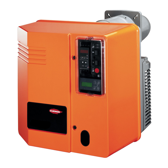
General information Burner characteristics Packaging Burner characteristics IME and AGP (Multi-Stage Injection and Proportional Air/Gas) dual fuel, single-unit burners C75, C100 are blast-air units with low gas pollution discharge (low NOx). They either operate on liquid or gas fuel, via TC control panel manual changeover switches. -
Page 29: Installation
Installation Assembly • Place the linking tubes of the Assembly Boiler face combustion components (stored on • Prepare face according to the stand-by) on the pump without pulling them too tight or gripping them too enclosed space requirement diagram.If required, insert a counter hard. -
Page 30: Gas/Electrical Connections
Installation Gas / electrical connections Gas connection Electrical connection Gas manifold • Connect electrical plate standby Connection of the gas distribution Electrical fittings and connections must system to gas manifold must be meet required standards. Earth must points on valve. performed by a qualified technician. -
Page 31: Fuel Oil Connection
(max. pressure 2 bars). Important: Suction: • Totally fill suction pipe between Double tube installation L (m) spray pump and tank down-pipe Corrected C 75 / C 100 with fuel oil. Ø (mm) Transfer loop: 10/12 12/14 14/16 • Fill, boost, drain and set pressure in circuit at 2bar max. -
Page 32: Start Up
Start up Preliminary checks / leakage test Setting air pressure switch Selecting fuel Burner start up simultaneously involves Setting air pressure switch • starting up installation by the fitter or his Check the connection of the flexible representative; only they can guarantee piping. - Page 33 Dual fuel Burner Dimension values. type power kW Y (mm) By reducing secondary air (dimension Y), increases and vice versa. • Turn screw V in the direction desired. C 75 C 100 1000 0306 / 13 013 497A...
- Page 34 5 slots open to the outside and 0 slot inside on 5 diffusers B according to shutter E position. Recommended setting C 75 B Propane gas - Groningen gas H 3 slots open to the outside +1 slot inside on 1 diffuser A according to shutter E position.
- Page 35 (1) US gal/h Pressure Fuel 45°B or 60°B Regul.1 bar Regul.2 kg/h rate rate 29,50 3,75 33,50 37,80 18,5 42,00 16,5 C 75 46,30 50,60 15,5 54,80 17,5 63,20 43,50 20,5 23,5 46,30 50,50 17,5 17,5 55,00 16,5 C 100...
- Page 36 In order to do this: • Adjust cam either by hand or with key. C 75 The angular position is found on red numbers in relation to each cam’s 10 index. • Cam drum rotates clockwise when air flows.
- Page 37 (V and N). It ensures a constant gas flow/air flow ratio and is quick-acting. The regulator also takes into account combustion chamber pF pressure. Burners C 75/100 B 517/8 The valve is delivered preset according to table here below. VEF 407 412 420 425 1,25...
-
Page 38: Settings
Start-up Description and settings VGD gas valve SKP70 regulator Pressure switch electrical connection (DIN 43650) Solenoid electrical connection (DIN 43650) Pressure switch Intake flange Pressure take-off G 1/8 before the filter External filter DN65 Identification plate Air pressure pL G 1/8 connection Adjusting screw R of gas flow/air flow ratio Adjusting screw D for correcting... - Page 39 Notes 0306 / 13 013 497A...
-
Page 40: Unit Lfl 1.333 Operation Program
Start up Unit LFL 1.333 Operation program 0306 / 13 013 497A... -
Page 41: Safety Unit Lfl 1.333 (Agp) Program
Start up Safety unit LFL 1.333 (AGP) program LFL 1.333 (AGP) Control and safety Program operating sequences: unit program Ignition transformer off, t1 : Preventilation time Motor switched on (terminal 6) shortly followed by end of safety time. t2 : 1st safety time when: t3 : Pre-ignition time main voltage is applied to... -
Page 42: Control Panel Tc
Start up Functions Control panel TC Switch functions on the control panel (TC) Standardized 48x48 or 48x96 mm positions for installation of a power regulator (option) B10 Measuring bridge [µA DC] of cell current, located next to the motor protection device F10 Fuse of the control panel (TC) Green indicators OIL fuel... -
Page 43: Fuel Oil Firing
Start up Description and settings of the fuel oil pump Fuel oil firing Firing effective output required. • Reduce the flow power at the min Warning: air flow regulation. Unit may be fired when all the • Check combustion. requirements listed in previous sections have been met. -
Page 44: Safety Checks
• Simultaneously disconnect both 33,50 microammeter cables. 37,80 18,5 Unit should immediately lockout. 42,00 16,5 • Refit measuring bridge and covers. C 75 • Disconnect mesurement appliances. 46,30 • Reclose pressure take-offs. 50,60 15,5 • Release cover. 54,80 17,5 Burner works on gas or fuel oil (both 63,20 are available). -
Page 45: Gas Firing
Start up Working cycle test Firing gas GAS working cycle test Firing Important: do not reset FUEL OIL valves must be closed Warning: dimension Y, if FUEL OIL has • Open, then immediately reclose fuel Unit may be only fired when all been set, otherwise : •... -
Page 46: Maintenance
Maintenance Removing the blast-tube. Motor-driven pump unit Important • Check the following : Maintenance operations should be This operation requires : either the opening of the burner performed at least once a year by a – – atomization pressure, technician. body and the boiler door, –... -
Page 47: Maintenance Gas
Gas maintenance • Check the following if failure occurs: If problem persists: After each operation: • Check various program symbols • Check combustion and all circuits – power supply (power and control), described here below on the control for possible leaks. –... -
Page 48: Maintenance Fuel Oil
Fuel oil maintenance • Check the following if failure occurs: If problem persists: Note • Check various program symbols After each operation: – power supply (power and control), • Check combustion and all circuits described here below on the control –... - Page 49 Notes 0306 / 13 013 497A...
- Page 50 0306 / 13 013 497A...
- Page 51 0306 / 13 013 497A...
- Page 52 CUENOD 18, rue des Buchillons Ville-la-Grand Fabriqué en EU. Made in EU. Hergestellt in EU. F - 74100 Annemasse Document non contractuel. Non contractual document. Angaben ohne Gewähr. 0306 / 13 013 497A...
Need help?
Do you have a question about the C 75 and is the answer not in the manual?
Questions and answers