Table of Contents
Advertisement
SERVICE MANUAL
Ver 1.0 2001. 07
AUDIO POWER SPECIFICATIONS
POWER OUTPUT AND TOTAL HARMONIC
DISTORTION:
With 3 ohm loads, from 22 – 200 Hz; rated 250 watts,
minimum RMS power, with no more than 0.8 % total
harmonic distortion from 250 milliwatts to rated
output.
System
Type
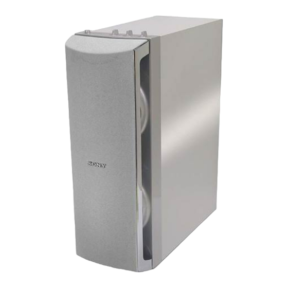
Active Subwoofer
Speaker unit
Woofer: 13.5 cm dia. (5
Continuous RMS output
US, Canadian model (0.8%) : 250 W
AEP, UK model (DIN) : 250 W
Other models (0.8%) : 250 W
Reproduction frequency range
22 Hz – 200 Hz
High frequency cut-off frequency
50 Hz – 200 Hz
Phase selector
NORMAL, REVERSE
Inputs
Input jacks
LINE IN: input pin jack
SPEAKER IN: input terminals (ELP plug 6P)
Sony Corporation
9-873-218-01
2001G1600-1
Home Audio Company
© 2001.7
Shinagawa Tec Service Manual Production Group
SPECIFICATIONS
3
/
in.), cone type
8
SA-WD200
Output jacks
LINE OUT: output pin jack
SPEAKER OUT: output terminals
General
Power requirements
US, Canadian model : 120 V AC, 60 Hz
AEP, UK model : 220 - 230 V AC, 50/60 Hz
Other models : 110 - 120, 220 - 240 V AC, 50/60 Hz
Power consumption
50 W
1 W (Standby mode)
Dimensions
Approx. 165 × 450 × 425 mm
× 17
× 16
(w/h/d) (6
1
/
3
/
3
/
2
4
4
Mass
16 kg (35 lb 4 oz)
Supplied accessories
Audio connecting cord
(1 phono plug – 1 phono plug) (1)
Speaker cords (1)
Design and specifications are subject to change without
notice.
ACTIVE SUBWOOFER
US Model
Canadian Model
AEP Model
UK Model
E Model
in.)
Advertisement
Table of Contents

Summary of Contents for Sony SA-WD200
- Page 1 SA-WD200 SERVICE MANUAL US Model Canadian Model Ver 1.0 2001. 07 AEP Model UK Model E Model SPECIFICATIONS AUDIO POWER SPECIFICATIONS Output jacks LINE OUT: output pin jack POWER OUTPUT AND TOTAL HARMONIC SPEAKER OUT: output terminals DISTORTION: With 3 ohm loads, from 22 – 200 Hz; rated 250 watts, General minimum RMS power, with no more than 0.8 % total...
-
Page 2: Safety Check-Out
CRITIQUES POUR LA SÉCURITÉ DE FONCTIONNEMENT. NE return to chassis, must not exceed 0.5 mA (500 microamperes). REMPLACER CES COMPOSANTS QUE PAR DES PIÈSES SONY Leakage current can be measured by any one of three methods. DONT LES NUMÉROS SONT DONNÉS DANS CE MANUEL OU DANS LES SUPPÉMENTS PUBLIÉS PAR SONY. - Page 3 SECTION 1 SA-WD200 DIAGRAMS 1-1. NOTE FOR PRINTED WIRING BOARDS AND SCHEMATIC DIAGRAMS • IC Block Diagrams Note on Printed Wiring Board: Note on Schematic Diagram: • All capacitors are in µF unless otherwise noted. pF: µµF • X : parts extracted from the component side.
- Page 4 SA-WD200 1-2. BLOCK DIAGRAM IC301(1/2) IC301(2/2) IC302(1/2) IC304(2/2) IC304(1/2) IC302(2/2) RV302 IC101(1/2) IC103(1/2) IC102(2/2) RV301 PHASE CONTROL POWER AMP BUFFER PHASE INVERTER CUT OFF FREQ. LEVEL CN101 ICE250A-SW SPEAKER IN 200Hz 50Hz (SPEAKERS) 50Hz 200Hz Q301 BOOST Q302 D919 D920...
-
Page 5: Printed Wiring Board - Control Section
SA-WD200 1-3. PRINTED WIRING BOARD — CONTROL SECTION — • See page 3 for Circuit Boards Location. IC102 IC103 IC101 IC201 IC301 IC304 IC302 • Semiconductor • Semiconductor • Location • Location • • [INPUT BOARD] [CONTROL BOARD] Ref. No. Location Ref. - Page 6 SA-WD200 1-4. SCHEMATIC DIAGRAM — CONTROL SECTION —...
-
Page 7: Printed Wiring Board - Power Section
SA-WD200 1-5. PRINTED WIRING BOARD — POWER SECTION — • See page 3 for Circuit Boards Location. • Semiconductor Location Ref. No. Location Ref. No. Location D701 D911 D801 D919 US,CND,AEP,UK AEP,UK,MY,SP D802 D920 D803 D921 D804 D922 D805 AEP,UK,MY,SP... - Page 8 SA-WD200 1-6. SCHEMATIC DIAGRAM — POWER SECTION — • See page 3 for IC Block Diagrams. IC B/D...
-
Page 9: Exploded Views
Ne les remplacer que par une pièce portant le numéro spécifié. • The mechanical parts with no reference number : Singapore model in the exploded views are not supplied. 2-1. SA-WD200 (OVERALL SECTION) not supplied not supplied not supplied Amp lifier section Ref. No. - Page 10 SA-WD200 2-2. SA-WD200 (AMPLIFIER BLOCK SECTION) supplied supplied Ref. No. Part No. Description Remarks Ref. No. Part No. Description Remarks A-4726-992-A POWER SUPPLY BOARD, COMPLETE (US, CND) 4-235-820-01 PANEL, REAR (EXCEPT MY, SP) A-4726-999-A POWER SUPPLY BOARD, COMPLETE (AEP, UK)
-
Page 11: Section 3 Electrical Parts List
SA-WD200 SECTION 3 AC SELECT ELECTRICAL PARTS LIST CONTROL INPUT NOTE: • RESISTORS • SEMICONDUCTORS In each case, u: µ, for example: • Due to standardization, replacements in the All resistors are in ohms. uA...: µA... , uPA... , µPA... ,... -
Page 12: Power Supply
SA-WD200 INPUT INPUT-SELECT POWER SUPPLY Ref. No. Part No. Description Remarks Ref. No. Part No. Description Remarks < DIODE > R208 1-249-417-11 CARBON 1/4W R209 1-249-429-11 CARBON 1/4W D101 8-719-991-33 DIODE 1SS133T-77 R210 1-249-429-11 CARBON 1/4W D102 8-719-991-33 DIODE 1SS133T-77... - Page 13 SA-WD200 POWER SUPPLY Ref. No. Part No. Description Remarks Ref. No. Part No. Description Remarks ∗ CN906 C805 1-104-666-11 ELECT 220uF 20.00% 25V 1-564-706-11 PIN, CONNECTOR (SMALL TYPE) 4P C806 1-126-964-11 ELECT 10uF 20.00% 50V CN907 1-757-828-11 LEAD (WITH CONNECTOR)
- Page 14 SA-WD200 POWER SUPPLY POWER-SW Ref. No. Part No. Description Remarks Ref. No. Part No. Description Remarks < IC > < RELAY > 0 IC901 8-749-017-79 IC STR-F6676 (AEP, UK, MY, SP) RY701 1-515-920-11 RELAY (24V) 0 IC901 6-700-162-01 IC STR-F6426S (US, CND)
- Page 15 SA-WD200 MEMO...
-
Page 16: Revision History
SA-WD200 REVISION HISTORY Clicking the version allows you to jump to the revised page. Also, clicking the version at the upper right on the revised page allows you to jump to the next revised page. Ver. Date Description of Revision...


Need help?
Do you have a question about the SA-WD200 and is the answer not in the manual?
Questions and answers