Table of Contents
Advertisement
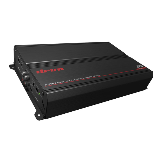
KS-DR3004
B5E-0091-10/01 [W]
WARNING
• If the fuse blows, first make sure the wires aren't touching to cause
a short circuit then replace the old fuse with one with the same
rating.
• Do not let pebbles, sand or metallic objects get inside the unit.
• Do not touch the unit during use because the surface of the unit
becomes hot and may cause burns if touched.
CAUTION
This unit is designed to operate on 12 V DC, NEGATIVE ground
electrical systems. JVC recommends consulting a qualified technician
for installation.
• To prevent short circuits while making connections, keep the
battery's negative terminal disconnected.
• This unit uses BTL (Balanced Transformerless) amplifier circuitry,
i.e., floating ground system, so comply with the following:
– Do not connect the "·" terminals of the speakers to each other.
– Do not connect the "·" terminals of the speakers to the metal
body or chassis.
• Cover the unused leads with insulating tape to prevent them from
short circuiting.
• DO NOT disassemble the unit since there are no user serviceable
parts inside.
• To keep the heat dissipation mechanism running effectively, wipe
the accumulated dust off periodically.
• Listening to the tape, radio, CD or digital audio player, etc. with
the volume set at a high level for a long period of time will exhaust
the battery, while the engine is turned off or while the engine is
idling.
• Use the speakers which have sufficient capacity to the unit.
POWER
AMPLIFIER: INSTRUCTION MANUAL
English
Advertisement
Table of Contents

Related Manuals for JVC KS-DR3004


Summary of Contents for JVC KS-DR3004
- Page 1 CAUTION This unit is designed to operate on 12 V DC, NEGATIVE ground electrical systems. JVC recommends consulting a qualified technician for installation. • To prevent short circuits while making connections, keep the battery’s negative terminal disconnected.
- Page 2 INSTALLATION TERMINAL CONNECTION English INSTALLATION The illustration above shows a typical installation. However, you should make adjustments corresponding to your specific car. A Location of the unit • Mount this unit on a firm surface, such as in the trunk or under the front seat.
- Page 3 (The cross section is about 0.8 mm to 8 mm ❶ Connect to metallic body or chassis. ❷-a When you use JVC car receiver with REMOTE OUTPUT, connect to REMOTE OUTPUT. ❷-b When you use a unit without REMOTE OUTPUT, connect to the accessory circuit of the car which is activated by the ignition switch.
- Page 4 SPEAKER CONNECTIONS English SPEAKER CONNECTIONS The proper lead connected to each SPEAKER OUTPUT terminal is AWG 18 to AWG 12. (The cross section is about 0.8 mm to 3.3 mm C 4-speaker system—Normal Mode • Use the speakers with an impedance of 2 Ω to 8 Ω. ①...
- Page 5 CONTROLS FRONT REAR English CONTROLS ① POWER indicator The green lamp lights while the unit is turned on. ② CROSSOVER filter switch OFF: Normally set to this position. LPF: Set to this position when you want to turn on the LPF (Low-Pass Filter) switch.
- Page 6 TROUBLESHOOTING English TROUBLESHOOTING The POWER indicator does not light. • Change the fuses if the current one is blown. • Connect the ground lead securely to a metal part of the car. • Confirm the battery voltage (11 V to 16 V). • Leave the unit turned off to cool it down if it heats up abnormally.
- Page 7 SPECIFICATIONS English SPECIFICATIONS Power Output Normal Mode: 60 W RMS × 4 channels at 4 Ω and ≤ 1% THD + N Signal-to-Noise Ratio: 80 dBA (reference: 1 W into 4 Ω) Power Output Normal Mode: 90 W RMS × 4 channels at 2 Ω and ≤ 1% THD + N Bridge Mode: 180 W RMS ×...
- Page 8 Manufacturer: JVC KENWOOD Corporation 3-12 Moriya-cho, Kanagawa-ku, Yokohama-shi, Kanagawa, 221-0022 Japan EU Representative: JVC Technical Services Europe GmbH Konrad-Adenauer-Allee 1-11, D - 61118 Bad Vilbel, Germany U.S.A FCC WARNING This equipment may generate or use radio frequency energy. Changes or modifications to this equipment may cause harmful interference unless the modifications are expressly approved in the instruction manual.