Siemens SINUMERIK 802D sl Programming And Operating Manual
Hide thumbs
Also See for SINUMERIK 802D sl:
- Function manual (462 pages) ,
- Programming and operating manual (364 pages) ,
- Instruction manual (262 pages)
Table of Contents
Advertisement
Quick Links
SINUMERIK
SINUMERIK_802D_sl
Grinding
Programming and Operating manual
Valid for
SINUMERIK 802D sl
06/2006
6FC5398-4CP10-0BA0
Software version
1
Preface
Description
Software interface
Programming
Cycles
Operating areas and operat-
ing modes
Define
Operator control (software)
Network operation
Data Backup
PLC diagnosis represented
as a ladder diagram
Application examples
1
2
3
4
5
6
7
8
9
10
11
Advertisement
Table of Contents

Related Manuals for Siemens SINUMERIK 802D sl


Summary of Contents for Siemens SINUMERIK 802D sl
- Page 1 Programming SINUMERIK_802D_sl Grinding Cycles Operating areas and operat- ing modes Programming and Operating manual Define Operator control (software) Network operation Data Backup PLC diagnosis represented as a ladder diagram Application examples Valid for Software version SINUMERIK 802D sl 06/2006 6FC5398-4CP10-0BA0...
- Page 2 Trademarks All names identified by ® are registered trademarks of the Siemens AG. The remaining trademarks in this publica- tion may be trademarks whose use by third parties for their own purposes could violate the rights of the owner.
- Page 3 The Internet version of the DOConCD (DOConWEB) is available at: http://www.automation.siemens.com/doconweb You can find information on the training courses offered and FAQs (frequently asked ques- tions) on the Internet under: http://www.siemens.com/motioncontrol (under "Support") Target group This publication is intended for programmers, planning engineers, machine operators and system operators.
- Page 4 Table 1 European and African time zone A&D Technical Support Phone: +49 (0) 180 / 5050 - 222 Fax: +49 (0) 180 / 5050 - 223 Internet: http://www.siemens.com/automation/support-request E-mail: mailto:adsupport@siemens.com Table 2 Asia and Australia time zone A&D Technical Support...
- Page 5 The EC Declaration of Conformity for the EMC Directive can be found/obtained ● on the Internet: http://www.ad.siemens.de/csinfo under product/Order No. 15257461 ● at the relevant regional office of the A&D MC Group of Siemens AG. Additional notes Note This symbol always appears in the document where further information is provided.
- Page 6 Preface Grinding Programming and Operating manual, 06/2006, 6FC5398-4CP10-0BA0...
-
Page 7: Table Of Contents
Table of contents Preface ..............................iii Description.............................. 1-1 Operating and display elements ....................1-1 Key definition of the full CNC keyboard (vertical format)............1-3 Key definition of the machine control panel ................1-4 Coordinate systems ........................1-5 Software interface........................... 2-1 Screen layout .......................... - Page 8 Table of contents 3.3.5 Circle with tangential transition: CT ..................3-38 3.3.6 Fixed point approach: G75....................... 3-38 3.3.7 Reference point approach: G74....................3-38 3.3.8 Measuring with touch-trigger probe: MEAS, MEAW ..............3-39 3.3.9 Feedrate F..........................3-40 3.3.10 Exact stop / continuous-path control mode: G9, G60, G64 ............. 3-41 3.3.11 Acceleration pattern: BRISK, SOFT..................
- Page 9 Table of contents 3.15 Oscillation..........................3-96 Cycles..............................4-1 Overview of cycles ........................4-1 Programming cycles ........................4-2 4.2.1 Call and return conditions ......................4-2 4.2.2 Messages output during execution of a cycle................4-2 4.2.3 Cycle call and parameter list...................... 4-3 Special characteristics of grinding cycles ..................
- Page 10 Table of contents Define ..............................6-1 Turning On and Reference Point Approach................6-1 Create new tool .......................... 6-3 Sense dresser .......................... 6-14 Sense workpiece........................6-15 Shaping/dressing ........................6-16 Sense probe..........................6-17 Program setting data........................ 6-18 Arithmetic parameter R ......................6-22 Assigning handwheels ......................
- Page 11 Table of contents Glossary ............................. Glossary-1 Index..............................Index-1 Tables Table 1 European and African time zone....................iv Table 2 Asia and Australia time zone ......................iv Table 3 American time zone ........................iv Table 1-1 Status and error displays ......................1-2 Table 2-1 Explanation of the screen controls in the status area..............
- Page 12 Table of contents Table 6-4 3. Cutting edge for grinding wheel ................... 6-11 Table 6-5 4. up to 6 cutting edge for grinding wheels ................6-12 Table 6-6 7. up to 9 cutting edge for dressers ..................6-13 Table 8-1 Required network parameters....................
-
Page 13: Description
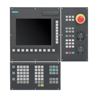
Description Operating and display elements Operator Controls The defined functions are called up via the horizontal and vertical softkeys. For a description, please refer to this manual: Figure 1-1 CNC operator panel Display of the LEDs on the operator panel CNC (PCU) The following LEDs are installed on the operator panel CNC. -
Page 14: Table 1-1 Status And Error Displays
RDY (green) Data Set Ready NC (yellow) Signoflife monitoring CF (yellow) Reading from/writing to CF card Note for the reader You can find information on error description in /DG/, SINUMERIK 802D sl, Diagnostics Manual Grinding Programming and Operating manual, 06/2006, 6FC5398-4CP10-0BA0... -
Page 15: Key Definition Of The Full Cnc Keyboard (Vertical Format)
Description 1.2 Key definition of the full CNC keyboard (vertical format) Key definition of the full CNC keyboard (vertical format) Grinding Programming and Operating manual, 06/2006, 6FC5398-4CP10-0BA0... -
Page 16: Key Definition Of The Machine Control Panel
Description 1.3 Key definition of the machine control panel Key definition of the machine control panel Grinding Programming and Operating manual, 06/2006, 6FC5398-4CP10-0BA0... -
Page 17: Coordinate Systems
Description 1.4 Coordinate systems Coordinate systems As a rule, a coordinate system is formed from three mutually perpendicular coordinate axes. The positive directions of the coordinate axes are defined using the so-called "3-finger rule" of the right hand. The coordinate system is related to the workpiece and programming takes place independently of whether the tool or the workpiece is being traversed. - Page 18 Description 1.4 Coordinate systems The origin of this coordinate system is the machine zero. This point is only a reference point which is defined by the machine manufacturer. It does not have to be approachable. The traversing range of the machine axes can by in the negative range. Workpiece coordinate system (WCS) To describe the geometry of a workpiece in the workpiece program, a right-handed, right- angled coordinate system is also used.
- Page 19 Description 1.4 Coordinate systems Figure 1-5 Workpiece on the machine Current workpiece coordinate system The programmed work offset TRANS can be used to generate an offset with reference to the workpiece coordinate system resulting in the current workpiece coordinate system resulting in the current workpiece coordinate system (see Section "Programmable work offset: TRANS").
- Page 20 Description 1.4 Coordinate systems Grinding Programming and Operating manual, 06/2006, 6FC5398-4CP10-0BA0...
-
Page 21: Software Interface
Software interface Screen layout Figure 2-1 Screen layout The screen is divided into the following main areas: ● Status area ● Application area ● Tip and softkey area Status area Figure 2-2 Status area Grinding Programming and Operating manual, 06/2006, 6FC5398-4CP10-0BA0... -
Page 22: Table 2-1 Explanation Of The Screen Controls In The Status Area
Software interface 2.1 Screen layout Table 2-1 Explanation of the screen controls in the status area Screen item Display Meaning ① Active operating area, active mode Position JOG; 1 INC, 10 INC, 100 INC, 1000 INC, VAR INC (evaluation by increments in JOG mode) JOG REF AUTOMATIC OFFSET PARAM... -
Page 23: Standard Softkeys
Software interface 2.2 Standard softkeys Table 2-2 Explanation of the screen controls in the tip and softkey area Screen item Display Meaning ① Recall symbol Pressing the Recall key lets you return to the next higher menu level. ② Information line Displays tips for the operator ③... -
Page 24: Operating Areas
To switch the operating area, press the relevant key (hard key) on the CNC full keyboard. Protection levels The SINUMERIK 802D sl provides a concept of protection levels for enabling data areas. The control system is equipped with default passwords for protection levels 1 to 3. -
Page 25: Accessibility Options
Software interface 2.4 Accessibility options Accessibility options 2.4.1 Calculator The calculator function can be activated from any operating area using <SHIFT + =>. For calculating, the four basic arithmetic operations are available, as well as the functions "sine", "cosine", "squaring" and "square root". A bracket function is provided to calculate nested terms. - Page 26 Software interface 2.4 Accessibility options Characters permitted for input +, -, *, / Basic arithmetic operations Sine function The X value (in degrees) in front of the input cursor is replaced by the sin(X) value. Cosine function The X value (in degrees) in front of the input cursor is replaced by the cos(X) value.
-
Page 27: Editing Chinese Characters
Software interface 2.5 The help system 2.4.2 Editing Chinese characters This function is only available in the Chinese language version. The control system provides a function for editing Chinese characters in the program editor and in the PLC alarm text editor. After activation, type the phonetic alphabet of the searched character in the input field. - Page 28 Software interface 2.5 The help system ● Brief description of all important operating functions ● Overview and brief description of the NC commands ● Explanation of the drive parameters ● Explanation of the drive alarms Operating sequence You can call up the help system from any operating area by pressing the info key or via the key combination <ALT+H>.
- Page 29 Software interface 2.5 The help system Figure 2-7 Help system: Description of the topic Use this function to select cross references. A cross reference is marked by the characters ">>..<<". This softkey is only displayed if a cross reference is displayed in the application area.
- Page 30 Software interface 2.5 The help system Grinding 2-10 Programming and Operating manual, 06/2006, 6FC5398-4CP10-0BA0...
-
Page 31: Programming
Programming Fundamental Principles of NC Programming 3.1.1 Program names Each program has its own program name. The name can be freely chosen during program creation, taking the following conventions into account: ● The first two characters must be letters; ● Use only letters, digits or underscore. ●... -
Page 32: Word Structure And Address
Programming 3.1 Fundamental Principles of NC Programming Table 3-1 NC program structure Word Word Word ; Comment ; 1. Set ; 2. Set ; ... ;End of program 3.1.3 Word structure and address Functionality/structure A word is a block element and mainly constitutes a control command. The word consists of ●... -
Page 33: Block Format
Programming 3.1 Fundamental Principles of NC Programming Extended address With the addresses Arithmetic parameters H function I, J, K Interpolation parameters/intermediate point Special function M, only affecting the spindle Spindle speed (Spindle 1 or 2) the address is extended by 1 to 4 digits to obtain a higher number of addresses. In this case, the value must be assigned using an equality sign "="... - Page 34 Programming 3.1 Fundamental Principles of NC Programming Note regarding block numbers First select the block numbers in steps of 5 or 10. Thus, you can later insert blocks and nev- ertheless observe the ascending order of block numbers. Block skip Blocks of a program, which are to be executed not with each program run, can be marked by a slash / in front of the block number.
-
Page 35: Character Set
Programming 3.1 Fundamental Principles of NC Programming 3.1.5 Character set The following characters are used for programming; they are interpreted in accordance with the relevant definitions. Letters, digits A, B, C, D, E, F, G, H, I, J, K, L, M, N,O, P, Q, R, S, T, U, V, W X, Y, Z 0, 1, 2, 3, 4, 5, 6, 7, 8, 9 No distinction is made between lowercase and uppercase letters. -
Page 36: Overview Of The Instructions - Grinding
Programming 3.1 Fundamental Principles of NC Programming 3.1.6 Overview of the instructions - grinding Functions available with SINUMERIK 802D sl plus and pro Address Meaning Value assignments Information Programming Tool offset number 0 ... 0 ... 9, only Contains offset data for a cer- D... - Page 37 Programming 3.1 Fundamental Principles of NC Programming Address Meaning Value assignments Information Programming Fixed point approach G75 X1=0 Z1=0 ;separate block, (machine axis identifier!) TRANS translation, programmable 3: Write memory TRANS X... Z... ;separate block SCALE Programmable scaling factor non-modal SCALE X...
- Page 38 Diameter dimensioning modally effective G290 * SIEMENS mode 47: External NC languages The functions marked with an asterisk (*) act when starting the program (in the default condition of the control system, unless otherwise programmed and if the machine manufacturer has preserved the default settings for the grinding technol- ogy).
- Page 39 Programming 3.1 Fundamental Principles of NC Programming Address Meaning Value assignments Information Programming H function ± 0.0000001 ... Value transfer to the PLC; H0=... H9999=... 9999 9999 meaning defined by the ma- (8 decimal places) chine manufacturer e.g.: H7=23.456 or with specification H9999= of an exponent: ±...
- Page 40 Programming 3.1 Fundamental Principles of NC Programming Address Meaning Value assignments Information Programming Mn=3 CW rotation of spindle (for spindle n) n = 1 or = 2 M2=3 ; CW rotation stop for spindle 2 Mn=4 CCW rotation of spindle (for spindle n) n = 1 or = 2 M2=4 ;...
- Page 41 Programming 3.1 Fundamental Principles of NC Programming Address Meaning Value assignments Information Programming ASIN() Arc sine R10=ASIN(0.35) ; R10: 20.487 degrees ACOS() Arc cosine R20=ACOS(R2) ; R20: ... Degrees ATAN2( , ) Arctangent2 The angle of the sum vector is R40=ATAN2(30.5,80.1) ;...
- Page 42 Programming 3.1 Fundamental Principles of NC Programming Address Meaning Value assignments Information Programming Absolute coordinate; It is also possible to specify the N10 A=ACP(45.3) ; Ap- approach position in dimensions for the end point of proach absolute position of the positive direction a rotary axis with ACP(...) irre- the A axis in (for rotary axis, spin-...
-
Page 43: Define
Programming 3.1 Fundamental Principles of NC Programming Address Meaning Value assignments Information Programming CYCLE411 Multiple plunge-cutting N10 CYCLE411(...) ; separa- te block CYCLE412 Shoulder plunge-cutting N10 CYCLE412(...) ; separa- te block CYCLE413 Oblique plunge-cutting N10 CYCLE4130(...) ;separate block CYCLE414 Radius grinding N10 CYCLE414(...) ;... - Page 44 Programming 3.1 Fundamental Principles of NC Programming Address Meaning Value assignments Information Programming Coordinate specified The dimension can be specified N10 G90 X10 Z=IC(20) ;Z - using incremental for the end or center point of a incremental dimension, dimensions certain axis irrespective of G90. X - absolute dimension Jump condition If the jump condition is fulfilled,...
- Page 45 Programming 3.1 Fundamental Principles of NC Programming Address Meaning Value assignments Information Programming $A..._..._ Timer for run time: 0.0 ... 10+300 System variable: TIME Time since the control system $AN_SETUP_TIME has last booted min (read only $AN_POWERON_TI Time since the control system value) has last booted normally N10 IF...
- Page 46 Programming 3.1 Fundamental Principles of NC Programming Address Meaning Value assignments Information Programming RNDM Modal rounding 0.010 ... 99 - Inserts roundings with the N10 X... Y..RNDM=.7.3 999.999 specified radius value tangen- ;modal rounding ON tially at the following contour N11 X...
-
Page 47: Positional Data
Programming 3.2 Positional data Positional data 3.2.1 Program dimensions In this section you will find descriptions of the commands, with which you can directly pro- gram dimensions taken from a drawing. This has the advantage that no extensive calcula- tions have to be made for NC programming. Note The commands described in this section stand in most cases at the start of a NC program. -
Page 48: Absolute/Incremental Dimensioning: G90, G91, Ac, Ic
Programming 3.2 Positional data ● Metric dimension, G71 applies for all linear axes in the block, until revoked by G70 in a following block. ● Inch dimension as for G70, but applies also for feedrate and length-related setting data. ● Metric dimension as for G71, but applies also for feedrate and length-related setting data. ●... -
Page 49: Dimensions In Metric Units And Inches: G71, G70, G710, G700
Programming 3.2 Positional data nate system). This is dependent on which offsets are currently active: programmable, settable, or no offsets. Upon program start, G90 is active for all axes and remains active until it is deselected in a subsequent block by G91 (incremental dimensioning data) (modally active). Incremental dimensioning G91 With incremental dimensioning, the numerical value of the path information corresponds to the axis path to be traversed. -
Page 50: Radius/Diameter Dimensions: Diamof, Diamon, Diam90
Programming 3.2 Positional data Programming example N10 G70 X10 Z30 ; Inch dimensions N20 X40 Z50 ;G70 continues to act N80 G71 X19 Z17.3 ; metric dimensioning from this point on Information Depending on the default setting you have chosen, the control system interprets all geomet- ric values as either metric or inch dimensions. - Page 51 Programming 3.2 Positional data For DIAM90, irrespective of the traversing method (G90/G91), the actual value of the trans- verse axis is always displayed as a diameter. This also applies to reading of actual values in the workpiece coordinate system with MEAS, MEAW, $P_EP[x] and $AA_IW[x]. Programming DIAMOF ;...
-
Page 52: Programmable Work Offset: Trans, Atrans
Programming 3.2 Positional data 3.2.5 Programmable work offset: TRANS, ATRANS Functionality The programmable work offset can be used: ● for recurring shapes/arrangements in various positions on the workpiece ● when selecting a new reference point for the dimensioning ● as a stock allowance when roughing This results in the current workpiece coordinate system. -
Page 53: Programmable Scaling Factor: Scale, Ascale
Programming 3.2 Positional data Programming example N10 ... N20 TRANS Z5 ; programmable offset, 5 mm in Z-axis N30 L10 ; Subroutine call; contains the geometry to be offset N70 TRANS ; offset cleared Subroutine call - see Section "Subroutine technique " 3.2.6 Programmable scaling factor: SCALE, ASCALE Functionality... - Page 54 Programming 3.2 Positional data Figure 3-6 Example of a programmable scaling factor Programming example N20 L10 ; Programmed contour original N30 SCALE X2 Z2 ; contour in X and Z enlarged 2 times N40 L10 Subroutine call - see Section "Subroutine technique " Information In addition to the programmable offset and the scale factor, the following functions exist: ●...
-
Page 55: Programmable Mirroring (Mirror, Amirror)
Programming 3.2 Positional data 3.2.7 Programmable mirroring (MIRROR, AMIRROR) Function MIRROR/AMIRROR can be used to mirror workpiece shapes on coordinate axes. All trav- ersing movements, which are programmed after the mirror call, e.g., in the subprogram, are executed in the mirror image. Programming MIRROR X0 Y0 Z0 (substituting instruction programmed in a separate NC block) AMIRROR X0 Y0 Z0 (additive instruction programmed in a separate NC block) - Page 56 Programming 3.2 Positional data Additive instruction, AMIRROR X Y Z A mirror image, which is to be added to an existing transformation, is programmed with AMIRROR. The currently set or last programmed coordinate system is used as the refer- ence. Deactivate mirroring For all axes: MIRROR (without axis parameter) Note...
- Page 57 Programming 3.2 Positional data The same applies to the direction of circle rotation (G2/G3 or G3/G2). Note If you program an additive rotation with AROT after MIRROR, you may have to work with reversed directions of rotation (positive/negative or negative/positive). Mirrors on the geome- try axes are converted automatically by the control into rotations and, where appropriate, mirrors on the mirror axis specified in the machine data.
-
Page 58: Settable Work Offset: G54 To G59, G507 To G512, G500, G53, G153
Programming 3.2 Positional data 3.2.8 Settable work offset: G54 to G59, G507 to G512, G500, G53, G153 Functionality The settable work offset specifies the position of the workpiece zero point on the machine (offset of the workpiece zero point with respect to the machine zero point). This offset is de- termined upon clamping of the workpiece into the machine and must be entered in the corre- sponding data field by the operator. -
Page 59: Programmable Working Area Limitation: G25, G26, Walimon, Walimof
Programming 3.2 Positional data Programming example N10 G54 ... ; 1st call settable work offset N20 X... Z... ; Machine the workpiece N90 G500 G0 X... ; Deactivate settable work offset 3.2.9 Programmable working area limitation: G25, G26, WALIMON, WALIMOF Functionality The working area for all the axes is defined by the working area limitation. - Page 60 ● For G25, G26, the channel axis identifier consisting of MD 20080 AXCONF_CHANAX_NAME_TAB is to be used. With SINUMERIK 802D sl, kinematic transformations (TRAANG) are possible. In some cases, different axis identifiers are configured for MD 20080 and for the geometry axis identifiers MD 20060: AXCONF_GEOAX_NAME_TAB.
-
Page 61: Axis Movements
Programming 3.3 Axis movements Axis movements 3.3.1 Linear interpolation with rapid traverse: G0 Functionality Die Eilgangbewegung G0 wird zum schnellen Positionieren des Werkzeuges benutzt, jedoch nicht zur direkten Werkstückbearbeitung. Es können alle Achsen gleichzeitig verfahren werden - auf einer geraden Bahn. For each axis, the maximum speed (rapid traverse) is defined in machine data. -
Page 62: Linear Interpolation With Feedrate: G1
Programming 3.3 Axis movements Programming example N10 G0 X100 Z65 ; Cartesian coordinates N50 G0 RP=16.78 AP=45 ;Polar coordinates Information Another group of G functions exists for moving into the position (see Section "Exact stop/continuous-path control mode: G60, G64"). For G60 exact stop, a window with various precision values can be selected with another G group. -
Page 63: Circular Interpolation: G2, G3
Programming 3.3 Axis movements Programming example N05 G54 G0 G90 X40 Z200 S500 M3 ; The tool traverses in rapid traverse, spindle speed = 500 r.p.m., clockwise N10 G1 Z120 F0.15 ; Linear interpolation with feedrate 0.15 mm/revolution N15 X45 Z105 N20 Z80 N25 G0 X100 ;... - Page 64 Programming 3.3 Axis movements Figure 3-13 Options for circular path programming with G2/G3, with G2 as an example G2/G3 remains active until canceled by another instruction from this G group (G0, G1, ...). The path velocity is determined by the programmed F word. Programming G2/G3 X...
- Page 65 Programming 3.3 Axis movements Programming example: Definition of center point and end point Figure 3-14 Example for center point and end point specification N5 G90 Z30 X40 ; Starting point circle for N10 N10 G2 Z50 X40 K10 I-7 ; End point and center point Note: Center point values refer to the circle starting point! Programming example: End point and radius specification Figure 3-15...
- Page 66 Programming 3.3 Axis movements Programming example: Definition of end point and aperture angle Figure 3-16 Example for end point and aperture angle specification N5 G90 Z30 X40 ; Starting point circle for N10 N10 G2 Z50 X40 AR=105 ; Opening angle and end point Programming example: Definition of center point and aperture angle Figure 3-17 Example for center point and aperture angle specification...
-
Page 67: Circular Interpolation Via Intermediate Point: Cip
Programming 3.3 Axis movements 3.3.4 Circular interpolation via intermediate point: CIP Functionality The direction of the circle results here from the position of the intermediate point (between starting and end points). Specification of intermediate point: I1=... for the X axis, K1=... for the Z axis. -
Page 68: Circle With Tangential Transition: Ct
Programming 3.3 Axis movements 3.3.5 Circle with tangential transition: CT Functionality With CT and the programmed end point in the current plane (G18: Z/X plane), a circle is pro- duced which tangentially connects to the previous path segment (circle or straight line). This defines the radius and center point of the circle from the geometric relationships of the previous path section and the programmed circle end point. -
Page 69: Measuring With Touch-Trigger Probe: Meas, Meaw
Measuring with touch-trigger probe: MEAS, MEAW Functionality The function is available for SINUMERIK 802D sl plus and pro. If the instruction MEAS=... or MEAW=... is in a block with traversing movements of axes, the positions of the traversed axes for the switching flank of a connected measuring probe are registered and stored. -
Page 70: Feedrate F
Programming 3.3 Axis movements Measuring result When the probe is successfully activated, the result of the measurement is available after the measuring block with the following variables for the axes traversed in the measuring block: axis in the machine coordinate system: $AA_MM[ axis in the workpiece coordinate system: $AA_MW[ axis... -
Page 71: Exact Stop / Continuous-Path Control Mode: G9, G60, G64
Programming 3.3 Axis movements Programming example N10 G94 F310 ;Feedrate in mm/min N110 S200 M3 ;Spindle rotation N120 G95 F15.5 ;Feedrate in mm/revolution Note: Write a new F word if you change G94 - G95. Information The G group with G94, G95 also contains the functions G96, G97 for the constant cutting rate. - Page 72 Programming 3.3 Axis movements The selection of the exact stop window has a significant influence on the total time if many positioning operations are executed. Fine adjustments require more time. Figure 3-20 Exact stop window coarse or fine, in effect for G60-G9; enlarged display of the windows Programming example N5 G602 ;Exact stop window coarse...
- Page 73 Programming 3.3 Axis movements lead to a significant jerk (acceleration change). The size of the jerk can be limited by activat- ing the SOFT function. Programming example N10 G64 G1 Z... F... ; Continuous-path mode N20 X... ; Continuous-path control mode continues to be active N180 G60 ...
-
Page 74: Acceleration Pattern: Brisk, Soft
Programming 3.3 Axis movements 3.3.11 Acceleration pattern: BRISK, SOFT BRISK The axes of the machine change their velocities using the maximum permissible acceleration value until reaching the final velocity. BRISK allows time-optimized working. The set velocity is reached in a short time. However, jumps are present in the acceleration pattern. SOFT The axes of the machine accelerate with nonlinear, constant curves until reaching the final velocity. -
Page 75: Percentage Acceleration Override: Acc
Programming 3.3 Axis movements 3.3.12 Percentage acceleration override: ACC Functionality Certain program sections can require the axis and spindle acceleration set via the machine data to be changed using the program. This programmable acceleration is a percentage ac- celeration override. For each axis (e.g. -
Page 76: Traversing With Feedforward Control: Ffwon, Ffwof
Programming 3.3 Axis movements 3.3.13 Traversing with feedforward control: FFWON, FFWOF Functionality Through feedforward control, the following error in the traversing path is almost zero. Traversing with feedforward control permits greater path accuracy and thus better production results. Programming FFWON ;... -
Page 77: Dwell Time: G4
Programming 3.3 Axis movements Programming example The 4th axis is a rotary axis with the axis identifier A N5 G94 ; feedrate F in mm/min or degrees/min N10 G0 X10 Z30 A45 ; X-Z traverse path with rapid traverse, A at the same time N20 G1 X12 Z33 A60 F400 ;... -
Page 78: Travel To Fixed Stop
Travel to fixed stop Functionality This function is available for SINUMERIK 802D sl plus and pro. The travel-to-fixed-stop (FXS = Fixed Stop) function can be used to establish defined forces for clamping workpieces, such as those required for sleeves and grippers. The function can also be used for the approach of mechanical reference points. - Page 79 Programming 3.3 Axis movements Programming example - selection N10 G1 G94 ... N100 X250 Z100 F100 FXS[Z1]=1 ; selected for machine axis Z1 FXS function, FXST[Z1]=12.3 ; Clamping torque 12.3%, FXSW[Z1]=2 ; window width 2 mm Notes ● When selected, the fixed stop must be located between the start and end positions. ●...
- Page 80 Programming 3.3 Axis movements Fixed endstop reached When the fixed stop has been reached: ● The distance-to-go is deleted and the position setpoint is manipulated, ● The drive torque increases to the programmed limit value FXST[ ]=... or the value from SD and then remains constant.
- Page 81 Travel to fixed stop is deselected. The deselection is not yet com- pleted. Query of the system variables in the parts program initiates a preprocessing stop. For SINUMERIK 802D sl, only the static states can be detected before and after selec- tion/deselection. Alarm suppression The issuing of the following alarms can be suppressed with machine data: ●...
-
Page 82: Spindle Movements
Programming 3.4 Spindle movements Spindle movements 3.4.1 Spindle speed S, directions of rotation Functionality The spindle speed is programmed under the address S in revolutions per minute, if the ma- chine has a controlled spindle. The direction of rotation and the beginning or end of the movement are specified via M commands. -
Page 83: Spindle Positioning: Spos
Programming 3.4 Spindle movements 3.4.2 Spindle speed limitation: G25, G26 Functionality In the program, you can limit the limit values that would otherwise apply by writing G25 or G26 and the spindle address S with the speed limit value. At the same time the values in the setting data are overwritten. -
Page 84: Gear Stages
Programming 3.4 Spindle movements Exception: First movement of the spindle, i.e. if the measuring system is not yet synchro- nized. In this case, the direction is specified in machine data. Other movement specifications for the spindle are possible with SPOS=ACP(...), SPOS=ACN(...), ... -
Page 85: Spindle
3.4.5 2. Spindle Function With SINUMERIK 802D sl plus and 802D sl pro, a 2nd spindle is provided. For these control systems, the kinematic transformation functions for grinding are possible. These functions require a second spindle for the driven workpiece. - Page 86 Programming 3.4 Spindle movements $P_S[n] ; Last programmed speed of spindle n $AA_S[n] ; Actual speed of spindle n $P_SDIR[ n ] ; Last programmed direction of rotation of spindle n $AC_SDIR[ n ] ; Current direction of rotation of spindle n 2 spindles installed The following can be interrogated in the program via the system variable: $P_NUM_SPINDLES...
-
Page 87: Special Functions
Programming 3.5 Special functions Special functions 3.5.1 Constant cutting rate: G96, G97 Requirement A controlled spindle must be present. Functionality With activated G96 function, the spindle speed is adapted to the currently machined work- piece diameter (transverse axis) such that a programmed cutting rate S remains constant on the tool edge: Spindle speed times diameter = constant. - Page 88 Programming 3.5 Special functions Deactivate constant cutting rate: G97 The function "Constant cutting rate" is deactivated with G97. If G97 is active, a programmed S word is given in RPM as the spindle speed . If no new S word is programmed, the spindle turns at the last defined speed with G96 func- tion active.
-
Page 89: Rounding, Chamfer
Programming 3.5 Special functions 3.5.2 Rounding, chamfer Functionality You can insert the chamfer (CHF or CHR) or rounding (RND) elements into a contour corner. If you wish to round several contour corners sequentially in the same manner, use the "Mo- dal rounding"... - Page 90 Programming 3.5 Special functions Figure 3-24 Inserting a chamfer with CHF using the example "Between two straight lines" Figure 3-25 Inserting a chamfer with CHR using the example "Between two straight lines" Programming examples of chamfer N5 F... N10 G1 X... CHF=5 ;...
- Page 91 Programming 3.5 Special functions Rounding RND or RNDM A circle contour element can be inserted with tangential connection between the linear and circle contours in any combination. Figure 3-26 Examples for inserting roundings Programming examples for rounding N5 F... N10 G1 X... RND=4 ;...
-
Page 92: Tool And Tool Offset
; Tool number: 1 ... 32 000 Note In the control system, you can simultaneously store the following maximum values: ● SINUMERIK 802D sl plus: 7 tools with 9 cutting edges each ● SINUMERIK 802D sl pro: 14 tools with 9 cutting edges each. Programming example N10 T1 D1 ;... -
Page 93: Tool Offset Number D (Grinding)
Programming 3.6 Tool and tool offset 3.6.2 Tool offset number D (grinding) Functionality It is possible to assign 1 to 9 (12) data fields with different tool offset blocks (for multiple cut- ting edges) to a specific tool. If a special cutting tool is required, it can be programmed with D and the corresponding number. - Page 94 Programming 3.6 Tool and tool offset N50 T4 D2 ; Load tool 4, D2 from T4 is active … N70 G0 Z... D1 ; D1 for tool 4 active, only cutting edge changed Contents of an offset memory ● Geometrical dimensions: Length, radius These consist of several components (geometry, wear).
-
Page 95: Selecting The Tool Radius Compensation: G41, G42
Programming 3.6 Tool and tool offset 3.6.3 Selecting the tool radius compensation: G41, G42 Functionality A tool with a corresponding D number must be active. The tool radius offset (cutting edge radius offset) is activated by G41/G42. The controller automatically calculates the required equidistant tool paths for the programmed contour for the respective current tool radius. - Page 96 Programming 3.6 Tool and tool offset Figure 3-29 Compensation to the right/left of the contour Starting the compensation The tool approaches the contour on a straight line and positions itself vertically to the path tangent in the starting point of the contour. Select the start point so as to ensure collision-free traversing.
-
Page 97: Corner Behavior: G450, G451
Programming 3.6 Tool and tool offset Programming example N10 T... F... N15 X... Z... ; P0 - starting point N20 G1 G42 X... Z... ; Selection right of contour, P1 N30 X... Z... ; ; Starting contour, circle or straight line 3.6.4 Corner behavior: G450, G451 Functionality... -
Page 98: Tool Radius Compensation Off: G40
Programming 3.6 Tool and tool offset Transition circle G450 The tool center point travels around the workpiece external corner in an arc with the tool ra- dius. In view of the data, for example, as far as the feedrate value is concerned, the transi- tion circle belongs to the next block containing traversing movements. -
Page 99: Special Cases Of The Tool Radius Compensation
Programming 3.6 Tool and tool offset Programming example N100 X... Z... ;Last block on the contour, circle or straight line, P1 N110 G40 G1 X... Z... ;Switch off tool radius compensation,P2 3.6.6 Special cases of the tool radius compensation Change of the compensation direction The G41 ⇄... -
Page 100: Example Of Tool Radius Compensation (Grinding)
Programming 3.6 Tool and tool offset Acute contour angles If very sharp outside corners occur in the contour with active G451 intersection, the control system automatically switches to transition circle. This avoids long idle motions. 3.6.7 Example of tool radius compensation (grinding) The wheel should have the contour shown in the figure. -
Page 101: Miscellaneous Function (M)
Programming 3.7 Miscellaneous function (M) ; Dressing contour section ① N110 X40 Z98 N120 Z118 ; Dressing contour section ① N130 X30 Z123 ; Dressing contour section ① ; Dressing contour section ① N140 Z123 N150 G0 X-90 ;Move clear N160 MIRROR ;... -
Page 102: H Function
(programmable logic controller). In all, a maximum of 10 such function outputs are possible in a block. Information With the SINUMERIK 802D sl plus and 802Dsl pro, two spindles are possible. This results in an expanded programming capability for the M commands - only for the spindles: M1=3, M1=4, M1=5, M1=40, ... -
Page 103: Arithmetic Parameters, Lud And Plc Variables
Programming 3.9 Arithmetic parameters, LUD and PLC variables Arithmetic parameters, LUD and PLC variables 3.9.1 Arithmetic parameter R Functionality The arithmetic parameters are used if an NC program is not only to be valid for values as- signed once, or if you must calculate values. The required values can be set or calculated by the control system during program execution. - Page 104 Programming 3.9 Arithmetic parameters, LUD and PLC variables Assignments to other addresses The flexibility of an NC program lies in assigning these arithmetic parameters or expressions with arithmetic parameters to other NC addresses. Values, arithmetic expressions and arithmetic parameters can be assigned to all addresses; Exception: addresses N, G, and L. When assigning, write the "...
-
Page 105: Local User Data (Lud)
Programming 3.9 Arithmetic parameters, LUD and PLC variables 3.9.2 Local User Data (LUD) Functionality The operator/programmer (user) can define his/her own variable in the program from various data types (LUD = Local User Data). These variables are only available in the program in which they were defined. -
Page 106: Reading And Writing Plc Variables
Programming 3.9 Arithmetic parameters, LUD and PLC variables Fields In addition to the individual variables, one or two-dimensional fields of variables of these data types can also be defined: DEF INT PVAR5[n] ; one-dimensional field, type INT, n: integer DEF INT PVAR6[n,m] ;... - Page 107 Programming 3.9 Arithmetic parameters, LUD and PLC variables $A_DBR[n] ; REAL data (32-bit value) "n" stands here for the position offset (start of data area to start of variable) in bytes Example: R1=$A_DBR[5] ; Reading a REAL value, Offset 5 ;...
-
Page 108: Program Jumps
Programming 3.10 Program jumps 3.10 Program jumps 3.10.1 Jump destination for program jumps Functionality A label or a block number serve to mark blocks as jump destinations for program jumps. Program jumps can be used to branch to the program sequence. Labelss can be freely selected, but must contain a minimum of 2 and a maximum of 8 letters o4r numbers of which the first two characters must be letters or underscores. -
Page 109: Conditional Program Jumps
Programming 3.10 Program jumps Figure 3-35 Unconditional jumps using an example 3.10.3 Conditional program jumps Functionality Jump conditions are formulated after the IF instruction. If the jump condition (value not zero) is satisfied, the jump takes place. The jump destination can be a block with a label or with a block number. - Page 110 Programming 3.10 Program jumps Comparison operations Operators Meaning Equal to < > Not equal to > greater than < less than > = greater than or equal to < = less than or equal to The comparison operations support formulating of a jump condition. Arithmetic expressions can also be compared.
-
Page 111: Program Example For Jumps
Programming 3.10 Program jumps Remark: The jump is executed for the first fulfilled condition. 3.10.4 Program example for jumps Task Approaching points on a circle segment: Table 3-4 Existing conditions: Starting angle 30 ° in R1 Circle radius 32mm in R2 Position spacing 10 °... -
Page 112: Subroutine Technique
Programming 3.11 Subroutine technique Explanation In block N10, the starting conditions are assigned to the corresponding arithmetic parame- ters. The calculation of the coordinates in X and Z and the processing takes place in N20. In Block N30, R1 is increased by spacing angle R3; R4 is decreased by 1. If R4 >... - Page 113 Programming 3.11 Subroutine technique Figure 3-37 Example of a sequence when a subroutine is called in a two-channel manner. Subroutine name The subprogram is given a unique name allowing it to be selected from several subroutines. When you create the program, the program name may be freely selected provided the fol- lowing conventions are observed: The same rules apply as for the names of main programs.
-
Page 114: Calling Machining Cycles
Please make sure that the values of your arithmetic parameters used in upper program lev- els are not inadvertently changed in lower program levels. When working with SIEMENS cycles, up to 7 program levels are needed. 3.11.2 Calling machining cycles... - Page 115 Programming 3.11 Subroutine technique Programming example N10 CYCLE83(110, 90, ...) ; Call of cycle 83, transfer values directly, ; separate block … N40 RTP=100 RFP= 95.5 ... ; Set transfer parameters for cycle 82 N50 CYCLE82(RTP, RFP, ...) ; Call of cycle 82, separate block Grinding 3-85 Programming and Operating manual, 06/2006, 6FC5398-4CP10-0BA0...
-
Page 116: Timers And Workpiece Counters
Programming 3.12 Timers and workpiece counters 3.12 Timers and workpiece counters 3.12.1 Runtime timer Functionality The timers are prepared as system variables ($A...) that can be used for monitoring the technological processes in the program or only in the display. These timers can only be read. -
Page 117: Workpiece Counter
Programming 3.12 Timers and workpiece counters Programming example N10 IF $AC_CUTTING_TIME>=R10 GOTOF WZZEIT ;Tool operation time limit value N80 WZZEIT: N90 MSG("Tool action time: Limit value reached") N100 M0 Display The contents of the active system variable is visible on the screen under <OFFSET/PARAM>... - Page 118 Programming 3.12 Timers and workpiece counters ● $AC_SPECIAL_PARTS- Number of workpieces specified by the user This counter allows user-defined workpiece counting. Alarm output can be defined for the case of identity with $AC_REQUIRED_PARTS (workpiece target). Users must reset the counter themselves. Programming example N10 IF $AC_TOTAL_PARTS==R15 GOTOF SIST ;...
-
Page 119: Inclined Axis
Programming 3.13 Inclined axis 3.13 Inclined axis 3.13.1 Inclined axis (TRAANG) Functionality The inclined axis function is intended for grinding technology and facilitates the following per- formance: ● Machining with an oblique infeed axis ● A Cartesian coordinate system can be used for programming purposes. ●... - Page 120 Programming 3.13 Inclined axis Example N10 G0 G90 Z0 MU=10 G54 F5000 -> ;Tool selection, ;clamping compensation, -> G18 G64 T1 D1 ;Plane selection N20 TRAANG(45) ; Enable inclined axis transformation N30 G0 Z10 X5 ;Approach start position N40 POS[X]=4.5 FA[X]=50 N50 TRAFOOF ;Deactivate transformation N60 G0 Z10 MU=10...
- Page 121 Programming 3.13 Inclined axis Machine manufacturer The following settings are defined in machine data: ● The angle between a machine axis and the oblique axis, ● The position of the zero point of the tool relative to the origin of the coordinate system specified by the "inclined axis"...
-
Page 122: Inclined Axis Programming (G05, G07)
Programming 3.13 Inclined axis 3.13.2 Inclined axis programming (G05, G07) Function In Jog mode, the movement of the grinding wheel can either be cartesian or in the direction of the inclined axis (the display stays cartesian). All that moves is the real U axis, the Z axis display is updated. - Page 123 Programming 3.13 Inclined axis Example ; Program angle for inclined axis N50 G07 X70 Z40 F4000 ;Approach starting position N60 G05 X70 F100 ;Oblique plunge-cutting N70 ... Grinding 3-93 Programming and Operating manual, 06/2006, 6FC5398-4CP10-0BA0...
-
Page 124: Multiple Feedrate Values In One Block
Programming 3.14 Multiple feedrate values in one block 3.14 Multiple feedrate values in one block Function The "Several feedrates in one block" function can be used independent of external analog and/or digital inputs to activate ● Different feedrates of an NC block, ●... - Page 125 Programming 3.14 Multiple feedrate values in one block Example of programming path motion The path feed is programmed under the address F and remains valid until an input signal is present. The numerical expansion indicates the bit number of the input that activates the feedrate when changed: F3=20 ;3 corresponds to input bit 3...
-
Page 126: Oscillation
Programming 3.15 Oscillation 3.15 Oscillation Function An oscillating axis travels back and forth between two reversal points 1 and 2 at a defined feedrate, until the oscillating motion is deactivated. Other axes can be interpolated as desired during the oscillating motion. A continuous infeed can be achieved via a path movement or with a positioning axis, however, there is no rela- tionship between the oscillating movement and the infeed movement. - Page 127 Programming 3.15 Oscillation Hold time Movement in exact stop area at reversal point Wait for exact stop fine >0 Wait for exact stop fine and then wait for stopping time The unit for the stopping time is identical to the stopping time programmed with G4. Example of an oscillating axis that should oscillate between two reversal points The oscillation axis Z must oscillate between 10 and 100.
- Page 128 Programming 3.15 Oscillation – with jerk limitation (SOFT) or – with acceleration curve with a knee (as positioning axes). Oscillation reversal points The current offsets must be taken into account when oscillation positions are defined: ● Absolute specification OSP1[Z]=value 1 Position of reversal point = sum of offsets + programmed value ●...
- Page 129 Programming 3.15 Oscillation Setting options These options are switched over. When OSE (end position) is programmed, option 4 is im- plicitly activated. Option value Meaning When the oscillation is deactivated, stop at the next reversal point (default) only possible by resetting values 1 and 2 When the oscillation is deactivated, stop at reversal point 1 When the oscillation is deactivated, stop at reversal point 2 When the oscillation is deactivated, do not approach reversal point if no...
- Page 130 Programming 3.15 Oscillation Grinding 3-100 Programming and Operating manual, 06/2006, 6FC5398-4CP10-0BA0...
-
Page 131: Cycles
● Shaping: Shaping: Provides for the desired shape of the wheel. ● Sharpening: Restores the cutting capability of the wheel. Grinding cycles The following cycles can be carried out using the SINUMERIK 802D sl control system: CYCLE410 Plunge-cut grinding CYCLE411... -
Page 132: Programming Cycles
Cycles 4.2 Programming cycles Programming cycles A cycle is defined as a subroutine with a name and parameter list assigned. 4.2.1 Call and return conditions The G functions effective prior to the cycle call and the programmable offsets remain active beyond the cycle. -
Page 133: Cycle Call And Parameter List
Cycles 4.2 Programming cycles program execution and continue to be displayed until the next message is displayed or the cycle is completed. The message texts and their meaning are listed together with the cycle to which they refer. Note A summary of alle messages is found in section "Error messages and error handling" in this manual. - Page 134 Cycles 4.2 Programming cycles If you want to exclude the last transfer parameters that have to be written in a call, you can prematurely terminate the parameter list with ")". If any parameters are to be omitted within the list, a comma "..., ,..." must be written as a placeholder. Note No plausibility checks are made of parameter values with a discrete or limited value range unless an error response has been specifically described for a cycle.
-
Page 135: Special Characteristics Of Grinding Cycles
Cycles 4.3 Special characteristics of grinding cycles Special characteristics of grinding cycles Call and return conditions The grinding cycles are programmed independently of the actual axis names. The collions- free approach to the grinding position is to be done in the higher-level program before the cycle is called. - Page 136 Cycles 4.3 Special characteristics of grinding cycles A tool length compensation must be selected before the cycle is called. It is always effective in the selected level and remains active even after the end of the cycle. Types of grinding wheels The cycles support two types of grinding wheels: vertical and inclined wheels.
-
Page 137: Zyklenunterstützung Im Programmeditor
Cycles 4.4 Zyklenunterstützung im Programmeditor Zyklenunterstützung im Programmeditor The program editor provides programming support for adding cycle calls to the program and for entering parameters. Function The cycle support offers the following functions: ● Cycle selection via soft keys ● Input screen forms for parameter assignment with help displays Decompilable program code is generated from the individual screens. - Page 138 Cycles 4.4 Zyklenunterstützung im Programmeditor To add a cycle call to the program, carry out the following steps one after the other: ● From the horizontal softkey bar, selection bars for the individual cycles can be changed using the <Grinding cycles> softkey. ●...
-
Page 139: Plunge-Cutting - Cycle410
Cycles 4.5 Plunge -cutting - CYCLE410 Plunge-cutting - CYCLE410 Function The plunge-cut cycle is called for the machining of a cylindrical seat if the wheel width is greater than or equal to the width of the seat to be machined. Either straight or inclined wheels are used. - Page 140 Cycles 4.5 Plunge -cutting - CYCLE410 Example for plunge-cutting The sample program below machines a seat to a diameter of 100 mm with reciprocation and direct-contact vibration pick-up. Table 4-2 Additional specified values: A_SR=0.2 mm Roughing allowance A_SL=0.1 mm Finishing allowance A_FSL=0.03 mm Fine-finishing allowance TIME=5 s...
- Page 141 Cycles 4.5 Plunge -cutting - CYCLE410 Machining by grinding is assigned the parameter B_ART, the value programmed taking into account the stock allowance, and the appropriate feedrate. The reciprocating motion and the subsequent retraction to the starting position are stopped at the end position for machining after expiry of a sparking-out time When using a measurement control, there is a compensation capability with the aid of the variable _GC_KORR.
- Page 142 Cycles 4.5 Plunge -cutting - CYCLE410 1 = roughing 2 = finishing and fine-finishing 3 = roughing, finishing and fine-finishing A_LU (air allowance) The term 'air allowance' is used to denote the distance between the starting position in X and the stock allowance for roughing.
- Page 143 Cycles 4.5 Plunge -cutting - CYCLE410 0 = No measurement control 1 = With measurement control KS (direct-contact vibration pick-up) The KS parameter is used to specify whether a caliper is used. 0 = without direct-contact vibration pick-up 1= with direct-contact vibration pick-up F_KS (feedrate for air grinding) With an air grinding feedrate, the path between the starting point and the point where the wheel comes into contact with the workpiece (with the aid of the direct-contact vibration pick-...
-
Page 144: Multiple Plunge-Cutting - Cycle411
Cycles 4.6 Multiple plunge-cutting – CYCLE411 Multiple plunge-cutting – CYCLE411 Function If the width of the area to be machined is larger than the wheel width, several plunge-cut op- erations are required. These are performed offset by one wheel width with an appropriate overlap. - Page 145 Cycles 4.6 Multiple plunge-cutting – CYCLE411 Parameter Data type Meaning ZU_ART Infeed -1 = only on the left 0 = on both sides 1 = only on the right BVU1 Dwell time at reversal point1 BVU2 Dwell time at reversal point2 F_PE real Feedrate for reciprocating in Z...
- Page 146 Cycles 4.6 Multiple plunge-cutting – CYCLE411 N10 T1 D1 M7 ; Determine technology values, coolant ON N20 S1=2000 M1=3 ; Turn on wheel speed N30 S2=1100 M2=4 ; Turn on workpiece speed N40 CYCLE411(1, 200, 30, 255, 15, 3, 5, ;...
- Page 147 Cycles 4.6 Multiple plunge-cutting – CYCLE411 When using a measurement control, there is a compensation capability with the aid of the variable _GC_KORR. This parameter specifies whether additional compensation should be computed for the measurement control. ● _GC_KORR = 0: Nominal/actual deviation is taken into account for the wheel ●...
- Page 148 Cycles 4.6 Multiple plunge-cutting – CYCLE411 The term 'air allowance' is used to denote the distance between the starting position in X and the stock allowance for roughing. A_SR, A_SL, A_FSL (allowance) For the various machining steps, different values can be defined for the allowance. These re- fer to the nominal diameter.
- Page 149 Cycles 4.6 Multiple plunge-cutting – CYCLE411 N_FR (number of sparking-out strokes) Once the finished dimension is reached when grinding by reciprocating, a number of addi- tional reciprocation strokes are performed without further infeed of the wheel. These strokes are called 'sparking-out strokes'. The number of the sparking-out strokes is defined in the N_FR parameter.
-
Page 150: Shoulder Plunge-Cutting - Cycle412
Cycles 4.7 Shoulder plunge-cutting – CYCLE412 Shoulder plunge-cutting – CYCLE412 Function The shoulder plunge-cutting cycle can be used to machine a workpiece shoulder by plunge- cutting in the Z direction. The direction depends on the cutting edge used (refer to "Tools and Tool Radius Compensation") Shoulder plunge-cutting involves only roughing and finishing. - Page 151 Cycles 4.7 Shoulder plunge-cutting – CYCLE412 Example for shoulder plunge-cutting Complete machining of a shoulder to a width of 50 mm with reciprocation using a direct- contact vibration pick-up. Additional specified values Z_SCH=50 mm Shoulder dimension in Z A_SR=0.2 mm Roughing allowance A_SL=0.1 mm Finishing allowance...
- Page 152 Cycles 4.7 Shoulder plunge-cutting – CYCLE412 plunge-cutting up to finishing allowance. After finishing and expiry of the sparking-out time, the reciprocation motion stops, and the wheel retracts to the starting position. Explanation of the parameters N_SITZ (seat number) The N_SITZ parameter is used to enter the number of the seat to be machined on the work- piece.
- Page 153 Cycles 4.7 Shoulder plunge-cutting – CYCLE412 A_SR Roughing allowance A_SL Finishing allowance F_SR, F_SL (feedrate) Different feedrates can be specified for the individual machining steps. They are program- med in [mm/min]. F_SR Feedrate for roughing F_SL Feedrate for finishing TIME (sparking-out time) After reaching the workpiece finished dimension, the tool dwells at the end position for a de- fined time.
-
Page 154: Oblique Plunge-Cutting - Cycle413
Cycles 4.8 Oblique plunge-cutting – CYCLE413 Oblique plunge-cutting – CYCLE413 Function The oblique plunge-cutting cycle is used for machining a cylindrical seat or for machining a shoulder and a diameter simultaneously. The wheel width must be greater than or equal to the width of the seat to be machined. -
Page 155: Table 4-2 Additional Specified Values
Cycles 4.8 Oblique plunge-cutting – CYCLE413 Parameter Data type Meaning F_KS real Feedrate for air grinding [mm/min] Example for oblique plunge-cutting Machining of a shoulder in Z to the finished dimension 50 mm and of a seat in X to the finish- ing diameter 200mm using CYCLE413;... - Page 156 Cycles 4.8 Oblique plunge-cutting – CYCLE413 X axis: Setpoint diameter + roughing allowance + air allowance Z axis: Shoulder dimension in Z + (roughing allowance + air allowance)*tan(angle) Note: If no angle is programmed 45° are used. A direct-contact vibration pick-up can be used for optional sparking, in which case the axes are traversed simultaneously at an angle ("inclined axis").
- Page 157 Cycles 4.8 Oblique plunge-cutting – CYCLE413 When performing oblique plunge-cutting using a straight wheel, this parameter must be pro- grammed. When an inclined wheel is used, the contents of the TPG8[ ] parameter (angle of the inclined wheel) are taken into account in the cycle. The contents of WIN are then ig- nored.
-
Page 158: Radius Grinding - Cycle414
Cycles 4.9 Radius grinding – CYCLE414 Radius grinding – CYCLE414 Function The radius grinding cycle is called whenever an internal or external radius is to be ground with continuous-path control. In this case, the workpiece radius must always be greater than the wheel radius. - Page 159 Cycles 4.9 Radius grinding – CYCLE414 N10 T1 D1 M7 ; Determine technology values, coolant ON N20 S1=2000 M1=3 ; Turn on wheel speed N30 S2=1100 M2=4 ; Turn on workpiece speed N40 CYCLE414(1, 55, 200, 10, 23, 5, 0.2, ;...
- Page 160 Cycles 4.9 Radius grinding – CYCLE414 Explanation of the parameters Figure 4-3 Internal corner (LAGE=23), external corner (LAGE=31) N_SITZ (seat number) The N_SITZ parameter is used to enter the number of the seat to be machined on the work- piece. Z_SCH (shoulder dimension in Z) The Z_SCH parameter is used to specify the width of the shoulder.
-
Page 161: Reciprocating - Cycle415
Cycles 4.10 Reciprocating – CYCLE415 KS (direct-contact vibration pick-up) The KS parameter is used to specify whether a caliper is used. 0 = without direct-contact vibration pick-up 1= with direct-contact vibration pick-up F_KS (feedrate for air grinding) With an air grinding feedrate, the path between the starting point and the point where the wheel comes into contact with the workpiece (with the aid of the direct-contact vibration pick- up) is traversed. - Page 162 Cycles 4.10 Reciprocating – CYCLE415 Parameter Data type Meaning A_SR real Roughing allowance (incr.) A_SL real Finishing allowance (incr.) A_FSL real Fine-finishing allowance (incr.) real Infeed amount for roughing (incr.) real Infeed amount for finishing (incr.) FSLZ real Infeed amount for fine-finishing (incr.) ZU_ART Infeed -1 = only on the left...
- Page 163 Cycles 4.10 Reciprocating – CYCLE415 N10 T1 D1 M7 ; Determine technology values, coolant ON N20 S1=2000 M1=3 ; Switch wheel speed N30 S2=1100 M2=4 ; Switch workpiece speed N40 CYCLE415 (1, 200, 30, 255, 3, 5, 0.5, ; Cycle call 0.3, 0.2, 0.2, 0.1, 0.005, -1, 0, 0, 80, 60, 50, 10, 5, 1, 3, 1, 1, 900) N50 M30...
- Page 164 Cycles 4.10 Reciprocating – CYCLE415 Explanation of the parameters N_SITZ (seat number) The N_SITZ parameter is used to enter the number of the seat to be machined on the work- piece. X_SOLL (setpoint diameter) The setpoint diameter corresponds to the finished dimension in the X direction. Z_ST (starting position in Z), Z_END (target position in Z) Z_ST and Z_END are used to define the starting and target positions of the grinding motion in the Z direction.
- Page 165 Cycles 4.10 Reciprocating – CYCLE415 SRZ, SLZ, FSLZ (infeed amount for roughing, finishing and fine-finishing) When grinding by reciprocating, the wheel is fed in at the reversal points, depending on the machining type (roughing, finishing or fine-finishing). The infeed amount is programmed us- ing the parameters SRZ, SLZ and FSLZ.
-
Page 166: Dressing And Profiling - Cycle416
Cycles 4.11 Dressing and profiling – CYCLE416 0 = without direct-contact vibration pick-up 1= with direct-contact vibration pick-up F_KS (feedrate for air grinding) With an air grinding feedrate, the path between the starting point and the point where the wheel comes into contact with the workpiece (with the aid of the direct-contact vibration pick- up) is traversed. -
Page 167: Table 4-6 Additional Specified Values
Cycles 4.11 Dressing and profiling – CYCLE416 Example for dressing Dressing of an inclined wheel by the dressing amount X_AB=0.04 mm using two dressing strokes. The dimensions of the wheel and the radius must be defined in D1. The following specifica- tions must be entered in the tool-specific offset data: Additional specified values: TPG5 = 58... - Page 168 Cycles 4.11 Dressing and profiling – CYCLE416 Sequence of operations When positioning the dresser in the X and Z directions, the starting position is offset by the amount of the retraction travel in the positive X direction. The wheel type (straight, inclined) selected for dressing depends on the entry in the tool- specific wheel parameter TPC1.
-
Page 169: General Workpiece Data - Cycle420
Cycles 4.12 General workpiece data – CYCLE420 4.12 General workpiece data – CYCLE420 Function Typically, general workpiece data are valid for each workpiece seat. Hence the cycle must be called at the beginning of a machining program and after each diameter or change to the tool peripheral speed. - Page 170 Cycles 4.12 General workpiece data – CYCLE420 Example for the general workpiece data CYCLE420 must be written at the start of each machining program. In the example, dressing is to be performed after every second machined workpiece using a dressing amount of X_AB=0.3 mm and two dressing strokes. The longitudinal position must be acquired for each newly clamped workpiece.
- Page 171 Cycles 4.12 General workpiece data – CYCLE420 Explanation of the parameters X_SOLL (maximum workpiece diameter) The X_SOLL parameter serves to calculate the workpiece speed. X_AB, Z_AB_L, Z_AB_R (dressing amount in X and Z) The dressing amount is the cutting depth by which the wheel is reduced in X or Z when dressing.
- Page 172 Cycles 4.12 General workpiece data – CYCLE420 N_AWST (number of workpieces before dressing) This parameter can be used to define how many workpieces are to be machined completely before the wheel is dressed. Grinding 4-42 Programming and Operating manual, 06/2006, 6FC5398-4CP10-0BA0...
-
Page 173: Error Messages And Error Handling
Cycles 4.13 Error messages and error handling 4.13 Error messages and error handling 4.13.1 General information If error conditions are detected in the cycles, an alarm is generated and the execution of the cycle is aborted. The cycles continue to output messages in the dialog line of the control. These message will not interrupt the program execution. - Page 174 Cycles 4.13 Error messages and error handling Alarm Alarm text Source Explanation, Remedy number CYCLE … 61506 Infeed path < 1mm Increase infeed path 61510 Dry run feed active 410, 411, 413, Switch off dry run feed 415, 420 61515 Free travel path <= dressing Change free travel path amount...
-
Page 175: Cycle Startup
Cycles 4.14 Cycle startup 4.14 Cycle startup 4.14.1 General To be able to work with the provided cycles, a minimum of prerequisites must be met by the machine (hardware) and the control system (software). These are described in the following sections. 4.14.2 Machine type The external cylindrical grinding machines that are used have two linear axes (X, Z), a grind-... - Page 176 Cycles 4.14 Cycle startup Machine data conditions The following settings must be made in the machine data: MD number Identifier Value 18080 MM_TOOL_MANAGEMENT_MASK= 'H4' '64a8 18094 MM_NUM_CC_TDA_PARAM= 10 '4b22 18096 MM_NUM_CC_TOA_PARAM= 10 '5306 18160 MM_NUM_USER_MACROS= 68 '5c38 In the area of general machine data, all additional parameters of the tool cutting edges, tools and the minimum number of macros must be activated.
-
Page 177: User Data
Cycles 4.14 Cycle startup Key (rapid input $A_IN[]) for initiating an intermediate dressing process, program abort and handwheel override (oscillation); The keys must either be directly wired or laid to the NCK interface through the PLC. For the oscillation, a stroke reversal must be initiated to immediately abort the oscillating motion, i.e. the signals must be decoded in the PLC. - Page 178 Cycles 4.14 Cycle startup Name Type Default Description Value _GC_LERF REAL Detected longitudinal position when setting up _GC_LVER REAL Offset during longitudinal position sensing _GC_LNPVZ REAL Initial Z zero shift during calibration _GC_LXPOS REAL X position while longiitudinal position is sensed _GC_PARR[20] REAL REAL type parameters for inter cycle as well as cycle HMI communi-...
-
Page 179: Auxiliary Macros
Cycles 4.14 Cycle startup Name Type Default Description Value _GC_IN_MZ3 Switch-over finishing measurement control _GC_IN_MZ4 Reserved for inputs/outputs _GC_IN_ABR Intermediate dressing upon key _GC_IN_HAND Handwheel key _GC_IN_BREAK Program interrupt key _GC_IN_HUB Stroke reversal key _GC_IN_FEEDSTOP Infeed stop key _GC_WEARTYP Selection of wear compensation, comparison or nominal dimensions _GC_RLXTYP Type of return position in MKS=0 WKS=1 _GC_SSTAT... - Page 180 Cycles 4.14 Cycle startup Ancillary macro Cycle variable from tools management DEFINE _T_LV $TC_DP13 DEFINE _T_LB $TC_DP22 DEFINE _T_HN $TC_DP5 DEFINE _T_HV $TC_DP14 DEFINE _T_HB $TC_DP23 DEFINE _D_IAB $TC_DP16[$P_TOOLNO,1] DEFINE _Z_IAB_L $TC_DP7[$P_TOOLNO,1] DEFINE _Z_IAB_R $TC_DP7[$P_TOOLNO,2] DEFINE _F_IZ $TC_DP20[$P_TOOLNO,1] DEFINE _F_ID_L $TC_DP10[$P_TOOLNO,1] DEFINE _F_IB_L $TC_DP11[$P_TOOLNO,1]...
- Page 181 Cycles 4.14 Cycle startup Ancillary macro Cycle variable from tools management DEFINE _IZWP $TC_TPC10[$P_TOOLNO] DEFINE _KONTURPRG $TC_DPC10[$P_TOOLNO,1] DEFINE _ABR_3 DEFINE _ZIEHEND DEFINE _STOSSEND DEFINE _ZIEHEND_ABR_1 DEFINE _STOSSEND_ABR_1 DEFINE _ZIEHEND_ABR_2 DEFINE _STOSSEND_ABR_2 DEFINE _DABRICHTER $TC_DP7 DEFINE _PROFTABR $TC_DPC7 DEFINE _ABRICHTERTYP $TC_DPC6 DEFINE _ABR1_X_V ABS($TC_DP8[$P_TOOLNO,1]) DEFINE _ABR1_Z_V...
- Page 182 Cycles 4.14 Cycle startup Grinding 4-52 Programming and Operating manual, 06/2006, 6FC5398-4CP10-0BA0...
-
Page 183: Operating Areas And Operating Modes
Operating areas and operating modes Offset Parameters operating area Functionality In the offset parameters operating area, the parameters required for machine operation are placed. Operating sequences This function opens the "Tool offset data" window which contains a list of the tools created. Use the cursor keys and the <Page Up>/<Page Down>... - Page 184 Operating areas and operating modes 5.1 Offset Parameters operating area Softkeys Clearing the calculated dresser data. Use this softkey to delete the tool. Opens a lower-level menu bar offering all functions required to create and display further tolol data. This function is used to enter - guided by the menu - the nomiinal dimensions and monitoring data of the grinding wheel.
-
Page 185: Machine Operating Area
Operating areas and operating modes 5.2 Machine operating area Machine operating area 5.2.1 JOG mode Operating sequences Use the <JOG> key on the machine control panel to select the Jog mode. To traverse the axes, press the appropriate key of the X or Z axes. The axes will traverse continuously at the velocity stored in the setting data until the key is released. -
Page 186: Table 5-1 Description Of The Parameters In The Jog Start Screen
Operating areas and operating modes 5.2 Machine operating area Parameter Table 5-1 Description of the parameters in the JOG start screen Parameter Explanation Displays the axes existing in the machine coordinate system (MCS) or in the workpiece coordinate system (WCS) If you traverse an axis in the positive (+) or negative () direction, a plus or minus sign will appear in the relevant field. - Page 187 Operating areas and operating modes 5.2 Machine operating area Menu tree Figure 5-3 JOG menu tree (grinding) Softkeys An explanation on the vertical softkeys is found in the MDA Section. This function is used to determine the dresser positions in the machine for dressers that are used by means of the geometry axes.
- Page 188 Operating areas and operating modes 5.2 Machine operating area Figure 5-4 Settings input screen Rectraction plane: The Face function retracts the tool to the specified position (Z position) af- ter the function has been executed. Safety clearance: Safety clearance to the workpiece surface This value defines the minimum distance between the workpiece surface and the workpiece.
-
Page 189: Mda Mode (Manual Input)
Operating areas and operating modes 5.2 Machine operating area 5.2.2 MDA mode (manual input) Functionality In the MDA mode, you can create or execute a part program. Caution The Manual mode is subject to the same safety interlocks as the fully automatic mode. Furthermore, the same prerequisites are required as in the fully automatic mode. -
Page 190: Table 5-2 Description Of The Parameters In The Mda Working Window
Operating areas and operating modes 5.2 Machine operating area Parameter Table 5-2 Description of the parameters in the MDA working window Parameter Explanation Displays the existing axes in the MCS or WCS If you traverse an axis in the positive (+) or negative () direction, a plus or minus sign will appear in the relevant field. - Page 191 Operating areas and operating modes 5.2 Machine operating area Use the <PageUp> or <PageDown> keys to display additional G functions. Selecting the softkey repeatedly will close the window. This window displays the auxiliary and M functions currently active. Selecting the softkey re- peatedly will close the window.
-
Page 192: Automatic Mode
Operating areas and operating modes 5.2 Machine operating area 5.2.3 Automatic mode Preconditions The machine is set up for the AUTOMATIC mode according to the specifications of the ma- chine manufacturer. Operating sequence Select Automatic mode by pressing the <Automatic> key on the machine control panel. The "AUTOMATIC"... -
Page 193: Table 5-3 Description Of The Parameters In The Working Window
Operating areas and operating modes 5.2 Machine operating area Menu tree Figure 5-8 Automatic menu tree Parameter Table 5-3 Description of the parameters in the working window Parameter Explanation Displays the existing axes in the MCS or WCS If you traverse an axis in the positive (+) or negative () direction, a plus or minus sign –... - Page 194 Operating areas and operating modes 5.2 Machine operating area Note If a second spindle is integrated into the system, the workspindle will be displayed using a smaller font. The window will always display the data of only one spindle. The control system displays the spindle data according to the following aspects: The master spindle is displayed: - Idle, - at spindle start...
- Page 195 Operating areas and operating modes 5.2 Machine operating area All the G functions are displayed. Use this softkey to display the "Axis feedrate" window. Pressing the softkey repeatedly will close the window. Use this softkey to switch from the seven-block to the three-block display. Switches the axis value display between the machine, workpiece and relative coordinate systems.
-
Page 196: Program Manager Operating Area
Operating areas and operating modes 5.3 Program Manager operating area The cursor is placed on the main program block of the interrupt point. The "Find" softkey provides the functions "Find line", "Find text" etc. Use this softkey to correct a fault program passage. Any changes will be stored immediately. Program Manager operating area Functionality Within the control system, the program manager operating area is the management area for... - Page 197 Operating areas and operating modes 5.3 Program Manager operating area Softkeys Use this softkey to display the directories of the NC. Use this softkey to select the program on which the cursor is placed for execution. The con- trol system will switch to the position display. With the next <NC START>, this program will be started.
- Page 198 Operating areas and operating modes 5.3 Program Manager operating area Selecting this softkey provides the functions required to read out / read in files via the RS232 interface and the function "Program execution from external". When the function is selected, the directories of the CF card are displayed.
-
Page 199: Program Operating Area
Operating areas and operating modes 5.4 Program operating area Program operating area Functionality A part program can only be edited if it is currently not being executed. Any modifications to the part program are stored immediately. Figure 5-11 Program editor start screen Menu tree Figure 5-12 Menu tree program (grinding) - Page 200 Operating areas and operating modes 5.4 Program operating area Operating sequence Select the program to be edited in the program manager. Press the <Open> softkey. The selected program opens. Softkeys Use this softkey to edit a file. Use this softkey to execute the selected file. Use this softkey to select a text segment up to the current cursor position (alternatively: <CTRL+B>) Use this softkey to copy a selected block to the clipboard (alternatively: <CTRL+C>)
-
Page 201: System Operating Area
Operating areas and operating modes 5.5 System operating area System operating area Functionality The "System" operating area provides all functions required for parameterizing and analyz- ing the NCK and the PLC. Depending on the functions selected, the horizontal and the vertical softkey bars change. The menu tree shown below only includes the horizontal softkeys. - Page 202 ● Manufacturer password ● User password It is possible to change certain data corresponding to the access levels. If you do not know the password, access will be denied. Note: Also see SINUMERIK 802D sl "Lists". Figure 5-15 Entering the password Grinding...
- Page 203 Operating areas and operating modes 5.5 System operating area Selecting the <APPLY> softkey sets the password. Use <ABORT> to return to the "system" main screen without performing any action. Change password Figure 5-16 Change password Depending on the access right, various possibilities are offered in the softkey bar to change the password.
-
Page 204: System Password (Start-Up)
Operating areas and operating modes 5.5 System operating area 5.5.1 System password (start-up) Commissioning Select the power-up mode of the NC. Use the cursor to select the appropriate mode. ● Normal power-up The system is restarted. ● Power-up with default data Cold restart with the default values (restores the default condition as on delivery) ●... -
Page 205: System Softkeys (Md)
Operating areas and operating modes 5.5 System operating area 5.5.2 System softkeys (MD) Machine data Any changes in the machine data have a substantial influence on the machine. Figure 5-17 Structure of a machine data line Table 5-4 Legend Meaning MD number Name Value... - Page 206 Operating areas and operating modes 5.5 System operating area Figure 5-18 The "Machine data" start screen Axis-specific machine data Open the "Axis-specific machine data" window. The softkey bar will be supplemented with the softkeys <Axis +> and <Axis >. Figure 5-19 Axis-specific machine data The data of axis 1 are displayed.
- Page 207 Operating areas and operating modes 5.5 System operating area Use this softkey to continue searching for the next match. This function provides various display filters for the active machine data group. Further soft- keys are provided: ● <Expert>: Use this softkey to select all data groups of the epert mode for display. ●...
- Page 208 Open the "Display machine data" window. Use the PageUp/PageDown keys to browse for- ward/backward. Note For a description of the machine data, please refer to the Manufacturer Documentations: "SINUMERIK 802D sl "Lists" "SINUMERIK 802D sl Description of Functions". Grinding 5-26 Programming and Operating manual, 06/2006, 6FC5398-4CP10-0BA0...
- Page 209 Operating areas and operating modes 5.5 System operating area Use the <Softkey color> and <Window color> softkeys to specify user-defined color settings. The displayed color consists of the components red, green and blue. The "Change color" window displays the values currently set in the input fields. The desired color can be produced by changing these values.
-
Page 210: System - Softkeys (Service Display)
Operating areas and operating modes 5.5 System operating area 5.5.3 System - softkeys (Service display) The "Service axes" window appears This window displays information on the axis drive. The <Axis +> or <Axis -> softkeys are also displayed. These can be used to display the val- ues for the next or previous axis. -
Page 211: Table 5-5 Data Groups
Operating areas and operating modes 5.5 System operating area Figure 5-26 Traverse log– This dialog can be used to select certain events for display. To switch between the "Display all data" and Display data groups" fields, use the TAB key. Figure 5-27 Action log settings Table 5-5... - Page 212 Operating areas and operating modes 5.5 System operating area Group Meaning Channel status Channel status IPO override switch Override value set Machine control panel Incoming alarm mes- NC / PLC alarms sages Deleted alarm messa- Canceled NC / PLC alarms Use this function to browse the event list for the entered term you are looking for.
- Page 213 Operating areas and operating modes 5.5 System operating area ● Changing and scaling of abscissa and ordinate; ● Measuring of a value using the horizontal or vertical marker; ● Measuring of abscissa and ordinate values as a difference between two marker positions; ●...
- Page 214 Operating areas and operating modes 5.5 System operating area Figure 5-31 Select signal ● Selecting the axis: To select the axis, use the "Axis" toggle field. ● Signal type: Following error Controller difference Contour deviation Position actual value Speed actual value Speed setpoint Compensation value Parameter block...
- Page 215 Operating areas and operating modes 5.5 System operating area <T mark ON> / <T mark OFF>softkeys are used to hide/show the gridlines Use the markers to determine the differences in the horizontal or vertical directions. To do this, place the marker on the start point and press <Fix V mark> or <Fix T mark>. The differ- ence between the starting point and the current marker position is now displayed in the status bar.
- Page 216 Operating areas and operating modes 5.5 System operating area Figure 5-33 Trace data Type the desired file name without extension in the "File name" field. Use the <Save> softkey to save the data with the specified name in the part program direc- tory.
-
Page 217: Table 5-6 Meanings Of The Entries Under [Dll Arrangement]
Operating areas and operating modes 5.5 System operating area This <Registry details> function displays a list of the assignment of the hard keys (function keys "Machine", "Offset", "Program", ...) for the programs to be started. For the meanings of the individual columns, please refer to the table below. Figure 5-35 Registry details Table 5-6... -
Page 218: System Softkeys (Plc)
Operating areas and operating modes 5.5 System operating area Figure 5-36 Font details The Change start DLL function is used to set the starting program. After the system has booted, the control system automatically starts the "Machine" operating area (SK 1). If a different starting behavior is desired, you can use this function to define a different starting behavior. -
Page 219: Table 5-7 Memory Areas
Operating areas and operating modes 5.5 System operating area Figure 5-37 Communication settings The baud rate is set using the toggle field. The following values are possible: 9600 / 19200 / 38400 / 57600 / 115200. Use this softkey to activate the connection between the control system and the PC/PG. It is waited for the call of the Programming Tool. - Page 220 Operating areas and operating modes 5.5 System operating area Figure 5-38 PLC status display The operand address displays the value incremented by 1. The operand address displays the value decremented by 1. Use this softkey to delete all operands. Cyclic updating of the values is interrupted. Then you can change the values of the oper- ands.
- Page 221 Operating areas and operating modes 5.5 System operating area Figure 5-39 PLC status list Use this softkey to change the value of the highlighted variable. Press the Accept softkey to confirm your changes. Use this softkey to assign the active column a new area. To this end, the interactive screen- form offers four areas to choose from.
- Page 222 Machine manufacturer Machine manufacturer 201 to 255 Siemens Siemens The notation is carried out for each program by lines. Two columns are intended per line, which must be separated from each other by TAB, space or the "|" character. In the first col- umn, the PLC reference number must be specified, and in the second column, the file name.
-
Page 223: System Softkeys (Start-Up Files)
Operating areas and operating modes 5.5 System operating area This function can be used to insert or modify PLC user alarm texts. Select the desired alarm number using the cursor. At the same time, the text currently valid is displayed in the input line. - Page 224 Operating areas and operating modes 5.5 System operating area Figure 5-43 Start-up files The individual data groups in the <802D data> area have the following meanings: ● data: Machine data Setting data Tool data R variables (R parameter) Work offset (zero shift) Compensation: Leadscrew error (SSFK) Global user data (user data) These data are special initialization data and are transferred in an ASCII file.
- Page 225 Operating areas and operating modes 5.5 System operating area Use this function to exchange data via a CompactFlash card. The following functions are provided to assist you: ● <Rename>: Use this function to rename a file selected beforehand using the cursor. ●...
-
Page 226: Table 5-8 Interface Parameters
Operating areas and operating modes 5.5 System operating area Interface parameters Table 5-8 Interface parameters Parameter Description Listing RTS/CTS The signal RTS (Request to Send) controls the Send mode of the data transfer device. Active: Data are to be sent. Passive: The Send mode is only quit after all data have been transmitted. -
Page 227: Alarms Operating Area
Operating areas and operating modes 5.6 Alarms operating area Alarms operating area Operating sequence The alarm window is opened. You can sort the NC alarms using softkeys; PLC alarms will not be sorted. Figure 5-45 Alarm display window Softkeys Use this softkey to display all alarms sorted by their priorities. The highest priority alarm is at the beginning of the list. - Page 228 Operating areas and operating modes 5.6 Alarms operating area Grinding 5-46 Programming and Operating manual, 06/2006, 6FC5398-4CP10-0BA0...
-
Page 229: Define
Define Turning On and Reference Point Approach Note When you turn on the SINUMERIK 802D sl and the machine, please also observe the Ma- chine Documentation, since turning on and reference point approach are machine- dependent functions. This documentation assumes an 802D standard machine control panel (MCP). Should you use a different MCP, the operation may be other than described herein. - Page 230 Define 6.1 Turning On and Reference Point Approach The "Reference point approach" window displays whether the axes are referenced. Press the arrow keys. If you select the wrong approach direction, no motion is carried out. Approach the reference points for each axis one after the other. Quit the function by switching the mode (MDA, AUTOMATIC or JOG).
-
Page 231: Create New Tool
Define 6.2 Create new tool Create new tool Functionality The tool offsets consist of various data describing the geometrty, the wear and the tool type. Each tool contains a defined number of parameters, depending on the tool type. Tools are identified by a number (T number). - Page 232 Define 6.2 Create new tool Figure 6-3 New tool Confirm your input using <OK>. Figure 6-4 Tool list A data record loaded with zero will be included in the tool list. This data block consists of 9 cutting edges (D fields). The first 6 cutting edges have a cutting edge type and are used as cutting edge geometry points.
- Page 233 Define 6.2 Create new tool For wheel having a free contour, the user is always responsible for the cutting edges. Only when a wheel is newly created or for deleted wear values, the cutting edge values are set by default once, depending on the dressing angle. The default setting is done for angle = 0, like for a simple vertical wheel, i.e.
-
Page 234: Table 6-1 Allocation Of Dressers
Define 6.2 Create new tool Cutting edges 7-9 are the three available dressing tools have a fixed allocation to the stan- dard contour cutting edge. Table 6-1 Allocation of dressers D field Dresser Assignment Dresser 1 Left-hand front cutting edge Dresser 2 Right-hand rear cutting edge Dresser 3... - Page 235 Define 6.2 Create new tool ● Vertical wheel with back-slopes (type 2) ● Left-hand side inclined wheel (type 3) ● Right-hand side inclined wheel (type 4) ● Free contour (type 0) The input screen is self-explaining. Note: A red dot shown in the diagrammatic sketch indicates the geometry value just being entered.
- Page 236 Define 6.2 Create new tool Dresser Use the <1st dresser>, <2nd dresser> or <3rd dresser> softkeys to access the dialog field for entering or verifying the dresser data. In the Type toggle field, the dresser type is selected. Fixed dresser: Tile/Diamond Rotating dresser: Shaping roller (for geo or auxiliary axes)
- Page 237 Define 6.2 Create new tool Parameter tables The function opens a summary of all cutting edge parameters. Note: This function is available only with a password set (Customer). Figure 6-11 The following table contains all cutting edge data. Table 6-2 Grinding wheel data, x=[1...n] y=[1...6] TPG1 Spindle number...
-
Page 238: Table 6-3 1. Cutting Edge 2. Cutting Edge For Left/Right Wheel Edge For Grinding Wheel
Define 6.2 Create new tool Table 6-3 1. Cutting edge 2. Cutting edge for left/right wheel edge for grinding wheel Tx Dy Tool type=403 Tx Dy Cutting edge position (1...9) Tx Dy real D - Diameter of new wheel Tx Dy real L - Distance of wheel reference point Tx Dy... - Page 239 Define 6.2 Create new tool Table 6-4 3. Cutting edge for grinding wheel Tx Dy Tool type=403 Tx Dy Cutting edge position (1...9) Tx Dy real D - Diameter of new wheel Tx Dy real L - Distance of wheel reference point Tx Dy real (reserved, length 3)
- Page 240 Define 6.2 Create new tool Table 6-5 4. up to 6 cutting edge for grinding wheels Tx Dy Tool type=403 Tx Dy Cutting edge position (1...9) Tx Dy real D - Diameter of new wheel Tx Dy real L - Distance of wheel reference point Tx Dy real (reserved, length 3)
- Page 241 Define 6.2 Create new tool Table 6-6 7. up to 9 cutting edge for dressers Tx Dy Tool type=403 Tx Dy Cutting edge position (1...9) Tx Dy real D - Diameter of new wheel Tx Dy real L - Distance of wheel reference point Tx Dy real (reserved, length 3)
-
Page 242: Sense Dresser
Define 6.3 Sense dresser Sense dresser Functionality This function is used to determine the dresser positions in the machine for dressers that are used by means of the geometry axes. The axis values are determinded in machine coordi- nates by the HMI and transmitted to the cycle. Operation The dresser is sensed in JOG mode. -
Page 243: Sense Workpiece
Define 6.4 Sense workpiece The calculation cycle will be started. Sense workpiece Functionality This function is used to detect the workpiece position in the machine with respect to the par- ticular axis. The HMI transmits both axis name and setpoint to the cycle. Operation The workpiece is sensed in JOG mode by scratching the respective axes. -
Page 244: Shaping/Dressing
Define 6.5 Shaping/dressing Shaping/dressing Functionality This function is used to shape a "raw" grinding wheel without generating an NC program. The procedure always refers to the currently active tool. Operation Shaping is done in JOG mode. The input screen is opened. Figure 6-14 Shaping The required shaper values that are machined in dressing strokes are entered using the in-... -
Page 245: Sense Probe
Define 6.6 Sense probe Sense probe Functionality This function is used to set the measuring position of the probe. The measuring position is set up for each particular workpiece For calibrating, no active tool is required. However, the workpiece must have been set up us- ing a valid tool since the longitudinal alignment position refers to the workpiece and the as- sociated zero shift Operation... -
Page 246: Program Setting Data
Define 6.7 Program setting data Note Both calibration and measurement must always be done in the same direction. Program setting data Functionality The setting data are used to define the settings for the operating states. These can be changed as necessary. Operating sequences These can be found on the Offset parameters operating area. - Page 247 Define 6.7 Program setting data A limitation of the spindle speed in the "Max." (G26) / "Min." (G25) fields can only be per- formed within the limit values defined in the machine data. Limitation using G96 Programmable upper speed limitation (LIMS) at constant cutting rate (G96). Dry run feed (DRY) The feedrate which can be entered here will be used instead of the programmed feedrate in the AUTOMATIC mode if the "Dry run feed"...
- Page 248 Define 6.7 Program setting data Figure 6-18 Times, Counters Meaning: ● Total parts: Number of workpieces produced in total (total actual value) ● Parts requested: Number of workpieces required (number of workpieces setpoint) ● Number of parts: This counter registers the number of all workpieces produced since the starting time.
- Page 249 Define 6.7 Program setting data Figure 6-19 General setting data Grinding 6-21 Programming and Operating manual, 06/2006, 6FC5398-4CP10-0BA0...
-
Page 250: Arithmetic Parameter R
Define 6.8 Arithmetic parameter R Arithmetic parameter R Functionality In the R parameter start screen, any R parameters that exist within the control system are listed. These can be changed as necessary. Figure 6-20 R parameters Operating sequence These can be found on the Offset parameters operating area. Select the <R parameters>... -
Page 251: Assigning Handwheels
Define 6.9 Assigning handwheels Assigning handwheels Operating sequence In JOG mode. select the <Handwheel> softkey. The "Handwheel" window appears on the screen. After the window has been opened, all axis identifiers are displayed in the "Axis" column, which simultaneously appear in the softkey bar. Select the desired handwheel using the cursor. - Page 252 Define 6.9 Assigning handwheels Grinding 6-24 Programming and Operating manual, 06/2006, 6FC5398-4CP10-0BA0...
-
Page 253: Operator Control (Software)
Operator control (software) Enter new program Operating sequences You have selected the Program Manager. Use the NC directory softkeys to select the storage location for the new program. Select the <New file> softkey to obtain a new dialog window into which the new main pro- gram or subroutine names are entered. -
Page 254: Edit The Parts Program
Operator control (software) 7.2 Edit the parts program Edit the parts program Functionality A part program can only be edited if it is currently not being executed. Any modifications to the part program are stored immediately. Figure 7-2 Program editor start screen Operating sequence Select the program to be edited in the program manager. -
Page 255: Select And Start Of A Part Program
Operator control (software) 7.3 Select and start of a part program Use this softkey to delete a selected text (alternatively: <CTRL+X>) Use the <Find> softkey to search for a string in the program file displayed. Type the term you are looking for in the input line and use the <OK> softkey to start the search. - Page 256 Operator control (software) 7.3 Select and start of a part program Figure 7-3 Program manager start screen Place the cursor bar on the desired program. Use the <Execute> softkey to select to program to be executed. The name of the selected program will appear in the "Program name"...
-
Page 257: Block Search
Operator control (software) 7.4 Block search Block search Operating sequence Requirements: The desired program has already been selected and the control system is in the RESET state. The block search function provides advance of the program to the required block in the part program. -
Page 258: Stop / Cancel A Part Program
Operator control (software) 7.5 Stop / cancel a part program Figure 7-6 Enter search term A toggle field is provided to define from which position you will search for the term. Search result The required block is displayed in the "Current block" window. Note For "Execute externally", no block search is possible. -
Page 259: Reapproach After Cancellation
Operator control (software) 7.6 Reapproach after cancellation Reapproach after cancellation After a program cancelation (RESET), you can retract the tool from the contour in Manual mode (JOG). Operating sequence Select Automatic operating mode Opening the Block search window for loading the interruption point. The interruption point is loaded. -
Page 260: Execute From External
Operator control (software) 7.8 Execute from external Execute from external Functionality Use this softkey to transmit an external program to the control system via the CF card; to execute this program, press <NC START>. While the contents of the buffer memory are being processed, the blocks are reloaded auto- matically. -
Page 261: Network Operation
Network operation Network operation Note The network function is only available for SINUMERIK 802D sl. Thanks to the integrated network adapter, the control system is network-capable. The follo- wing connections are possible: ● Peer-to-Peer Direct connection between control system and PC using a cross-over cable ●... - Page 262 Network operation 8.1 Network operation Select the <Service network> softkey to obtain access to the network parameters input screen. Figure 8-1 Network parameters Table 8-1 Required network parameters Parameter Explanation DHCP DHCP log: A DHCP server is needed in the network which dynamically distrib- utes the IP addresses.
-
Page 263: User Management
Network operation 8.1 Network operation Figure 8-2 Firewall configuration The RCS network requires the ports 80 and 1597 for communication. To change the port status, select the relevant port using the cursor. Pressing the Input key changes the port status. Open ports are shown with the checkbox enabled. -
Page 264: User Log In - Rcs Log In
Network operation 8.1 Network operation Figure 8-3 User accounts The user accounts serve for saving personal settings of the users. To create a new account, type the user name and the log-in password in the input fields. Use the <Create> softkey to insert a new user into the user management. Use the <Delete>... -
Page 265: Working On The Basis Of A Network Connection
Network operation 8.1 Network operation Logon Type user name and password into the appropriate input fields and select the <Log in> soft- key to confirm. After successful log-in, the user name is displayed in the Current user line. Select the <Back> softkey to close the dialog box. Note This log-in simultaneously serves for user identification for remote connections. -
Page 266: Sharing Directories
Network operation 8.1 Network operation 8.1.5 Sharing directories This function defines the rights for access of remote users to the file system of the control system. Use the Program manager to select the directory you want to share. Use the <Share> softkey to open the input screen for sharing the selected directory. Figure 8-5 Sharing status ●... -
Page 267: Connecting / Disconnecting Network Drives
Network operation 8.1 Network operation 8.1.6 Connecting / disconnecting network drives Press the <Service display> <Service control system> softkeys in the system operating area. Use <Service network> <Connect/Disconnect> to enter the network drive configuration area. Figure 8-6 Network connections Connecting network drives The <Connect>... - Page 268 Network operation 8.1 Network operation Figure 8-7 Connecting network drives Place the cursor on an unused drive designator and use the TAB key to switch to the Path input field. Specify the IP address of the server and the the share name. Example: \\192.4.5.23\TEST\ The <Connect>...
-
Page 269: Rcs Tool
802. With this key, the connection to the control system can be established via a local network (only for SINUMERIK 802D sl pro) and the remote operating function and other functions can be used. Without a license key, only local directories (on the PC/PG) are released for accessing via the control system. - Page 270 Network operation 8.2 RCS tool Grinding 8-10 Programming and Operating manual, 06/2006, 6FC5398-4CP10-0BA0...
-
Page 271: Data Backup
Data Backup Data transfer via the RS232 interface Functionality The RS232 interface of the control system can be used to output data (e.g. part programs) to an external data backup device or to read in data from there. The RS232 interface and your data backup device must be matched with each other. - Page 272 Data Backup 9.1 Data transfer via the RS232 interface Use <Send> to start the data transfer. All data copied to the clipboard will be transmitted. Further softkeys Load files via the RS232 interface. Transmission protocol This log contains all transmitted files including status information: ●...
-
Page 273: Creating / Reading In / Reading Out A Start-Up Archive
9.2 Creating / reading in / reading out a start-up archive Creating / reading in / reading out a start-up archive Note /BA/ SINUMERIK 802D sl "Instruction Manual", Section "Data backup and machine series start-up" Operating sequence Select the <Commissioning files> softkey which is to be found in the "System" operating area. - Page 274 Data Backup 9.2 Creating / reading in / reading out a start-up archive Figure 9-3 Contents of the start-up archive Write the commissioning archive to a CompactFlash card Requirements: The CF card is inserted, and the commissioning archive has been copied to the clipboard.
-
Page 275: Reading In / Reading Out Plc Projects
Data Backup 9.3 Reading in / reading out PLC projects Reading the commissioning archive from the CompactFlash card To import a start-up backup, perform the following operator actions: 1. Insert the CF card. 2. Press the <Customer CF card> softkey and select the line with the desired archive file. 3. - Page 276 Data Backup 9.3 Reading in / reading out PLC projects Grinding Programming and Operating manual, 06/2006, 6FC5398-4CP10-0BA0...
-
Page 277: Plc Diagnosis Represented As A Ladder Diagram
PLC diagnosis represented as a ladder diagram Functionality A PLC user program consists to a large degree of logical operations to realize safety func- tions and to support process sequences. These logical operations include the linking of vari- ous contacts and relays. As a rule, the failure of a single contact or relay results in a failure of the whole system/installation. -
Page 278: Screen Layout
PLC diagnosis represented as a ladder diagram 10.1 Screen layout 10.1 Screen layout The screen layout with its division into the main areas corresponds to the layout already de- scribed. Any deviations and amendments pertaining to the PLC diagnosis are shown below. Figure 10-1 Screen layout Table 10-1... -
Page 279: Operating Options
PLC diagnosis represented as a ladder diagram 10.2 Operating options 10.2 Operating options In addition to the softkeys and the navigation keys, this area provides still further key combi- nations. Hotkeys The cursor keys move the focus over the PLC user program. When reaching the window borders, it is scrolled automatically. - Page 280 PLC diagnosis represented as a ladder diagram 10.2 Operating options Softkeys The <PLC Info> window gives information about the PLC model, the PLC system version, cycle time and PLC user program runtime. Figure 10-2 PLC info Use the Reset machin. time softkey to refresh the data shown in the window. Use "PLC status"...
- Page 281 PLC diagnosis represented as a ladder diagram 10.2 Operating options Figure 10-4 Status list This window displays all logical and graphical information of the PLC program running in the appropriate program block. The logic in the LAD (ladder diagram) is divided into clearly structured program parts and current paths, called networks.
- Page 282 PLC diagnosis represented as a ladder diagram 10.2 Operating options Figure 10-6 Selecting the program block Selecting this softkey displays the description of the selected program block which was stored when the PLC project was created. Figure 10-7 Properties of the selected PLC program block Selecting this softkey displays the table of local variables of the selected program block.
- Page 283 PLC diagnosis represented as a ladder diagram 10.2 Operating options Figure 10-8 Table of local variables for the selected PLC program block Texts which are longer than the column width are cut in all tables and the "~" character is at- tached.
- Page 284 PLC diagnosis represented as a ladder diagram 10.2 Operating options Figure 10-9 "Program status" ON – symbolic representation Figure 10-10 "Program status" ON – absolute representation Use this softkey to switch between the absolute and symbolic representation of the oper- ands.
- Page 285 PLC diagnosis represented as a ladder diagram 10.2 Operating options A dialog box is displayed from which various search criteria can be selected. The <Abso- lute/symbol. address> softkey can be used to search for a certain operand matching this cri- terion in both PLC windows.
- Page 286 PLC diagnosis represented as a ladder diagram 10.2 Operating options Figure 10-12 Search for absolute operands If the search object is found, use the <Continue search> softkey to continue the search. Selecting this softkey displays all symbolic identifiers used in the highlighted network. Figure 10-13 Network symbol information table Use this softkey to display the list of cross references.
- Page 287 PLC diagnosis represented as a ladder diagram 10.2 Operating options Figure 10-14 Cross references main menu (absolute) Figure 10-15 Cross references main menu (symbolic)) You can open the appropriate program segment directly in the 1/2 window using the <Open in Window 1/2> function. Depending on the active type of representation, the elements are displayed either with abso- lute or symbolic identifiers.
- Page 288 PLC diagnosis represented as a ladder diagram 10.2 Operating options You want to view the logic interrelation of the absolute operand M251.0 in network 1 in pro- gram block OB1. After the operand has been selected from the cross-reference list and the <Open in Window 1>...
- Page 289 PLC diagnosis represented as a ladder diagram 10.2 Operating options ● Down (from the current cursor position) ● Whole program block (from the beginning) Figure 10-18 Searching for operands in cross references The text you are looking for is displayed in the notes line. If the text is not found, a corre- sponding error message is displayed which must be confirmed with <OK>.
- Page 290 PLC diagnosis represented as a ladder diagram 10.2 Operating options Grinding 10-14 Programming and Operating manual, 06/2006, 6FC5398-4CP10-0BA0...
-
Page 291: Application Examples
Application examples 11.1 Cycle example 1 Example 1 The following workpiece is to be grinded. Z+ machining direction is to be selected. The ma- chining steps are given in the example drawing. Figure 11-1 Z+ machining direction Grinding 11-1 Programming and Operating manual, 06/2006, 6FC5398-4CP10-0BA0... - Page 292 Application examples 11.1 Cycle example 1 Table 11-1 Programming Program block Description N10 T1 D2 M23 N20 CYCLE420( 160, 0.02, 0.005, 0.005, 0.15, 0.15, 0.15, Basic data 0.15, 0.15, 10, 20, 20, 0, , , , 1, 5) N30 CYCLE413( 0, 160.1, 100, -45, 3, ,0.1, 0.03, 0.01, Right-hand plunge- 0.8, 0.3, 0.05, 1, 0, 0, 5) cuttiing...
- Page 293 Application examples 11.2 Cycle example 2 11.2 Cycle example 2 Example 1 The following workpiece is to be grinded. Machining is done in Z-.The machining steps are given in the drawing. Figure 11-2 Machining in Z- direction Table 11-2 Programming Program block Description N10 T1 D2 M23...
- Page 294 Application examples 11.2 Cycle example 2 Program block Description N40 T1 D2 N50 CYCLE412( 0, -160, 170, 3, 0.1, 0.1, 0.05, Right-hand face plunge-cuttiing 1, 0.5, 1, 0, 5, 10, 2000) N60 T1 D4 N70 CYCLE411( 0, 160.1, -161, -260, 5, 1, ,0.4, Multiple plunge-cutting, only 0.03, 0.01, 0.01, 0.005, 0, 1, 1, 3000, 0.8, roughing from right to left...
-
Page 295: Glossary
Glossary Effective wheel width Wheel width of the inclined grinding wheel which is used to machine the diameter. It is de- pendent upon: ● the physical width ● the evading height ● the angle of the wheel Evasion/evasion angle Tapering of the left or right side of the grinding wheel for face-grinding operations in which a so-called cross-grinding is produced. - Page 296 Glossary Shoulder Left or right side of the grinding wheel or of the tool Workpiece peripheral speed in m/min XWP/ZWP when dressing a free contour Workpiece offset for offsetting the programmed contour to the current cutting edge of the grinding wheel; which is necessary so that workpiece coordinates can be programmed in the free contour.
-
Page 297: Index
Index Files Copy, 2-7 Paste, 2-7 A, 3-89 Access right, 2-4 Address, 3-2 AMIRROR, 3-25 G05, 3-92 Arithmetic parameters, 6-22 G07, 3-92 Asynchronous oscillation, 3-96 G1, 3-97 Axis assignment, 4-2 G4, 3-97 Block format, 3-3 Hand wheel, 6-23 Block search, 7-5 Help system, 2-7 Hold time, 3-96 Hot keys, 2-7... - Page 298 Index Protection levels, 2-4 Network connection, 8-1 Network operation, 8-1 Network parameters, 8-1 Non-printable special characters, 3-5 RCS log in, 8-4 RCS tool, 8-9 Reapproach after cancellation, 7-7 Reapproach after interruption, 7-7 Reference point approach, 6-1 Offset Parameters operating area, 5-1, 6-3 Return conditions, 4-2 Online help, 2-7 RS232 interface, 9-1...