Table of Contents
Advertisement
Quick Links
Advertisement
Table of Contents

Related Manuals for Patton electronics SmartNode 2294


Summary of Contents for Patton electronics SmartNode 2294
- Page 1 Model 2292 & 2294 Leased-Line Extenders over IP Getting Started Guide Sales Office: +1 (301) 975-1000 Technical Support: +1 (301) 975-1007 E-mail: support@patton.com WWW: www.patton.com Part Number: 07M2292-GS, Rev. A Revised: April 13, 2009...
- Page 2 Patton Electronics Company, Inc. 7622 Rickenbacker Drive Gaithersburg, MD 20879 USA tel: +1 (301) 975-1000 fax: +1 (301) 869-9293 support: +1 (301) 975-1007 web: e-mail: Trademark Statement The terms SmartWare and SmartView are trademarks of Patton Electronics Company. All other trademarks presented in this document are the property of their respective owners.
-
Page 3: Summary Table Of Contents
Summary Table of Contents General information... 14 Applications overview... 19 Hardware installation... 21 Getting started with the SmartNode... 32 LEDs status and monitoring Contacting Patton for assistance Compliance information ... 41 Specifications ... 43 Cabling ... 46 Port pin-outs ... 50 Installation checklist ... -
Page 4: Table Of Contents
Table of Contents Summary Table of Contents Table of Contents ... 4 List of Figures ... 6 List of Tables ... 7 About this guide ... 8 Safety when working with electricity Preventing electrostatic discharge damage General observations ...11 General conventions ...12 General information... - Page 5 Model 2292 & 2294 Series Getting Started Guide Warranty coverage ...39 RMA numbers ...40 Compliance information ... 41 Compliance ...42 ...42 Safety ...42 CE Declaration of Conformity ...42 Specifications ... 43 Capacity ...44 Audio connectivity ...44 Data Services ...44 Quality of Service ...44 Voice Signaling...44...
-
Page 6: List Of Figures
Connecting a SmartNode 2294 Series device to a hub ....... . -
Page 7: List Of Tables
RJ-11 socket ................27 Ethernet 10/100Base-T (RJ-45) port pin-outs (SmartNode 2294 Series) ......28 Factory default IP address and network mask configuration . -
Page 8: About This Guide
About this guide This guide describes the SmartNode 2294 and 2292 Series hardware, installation and basic configuration. For detailed software configuration information refer to the SmartWare Software Configuration Guide and the avail- able Configuration Notes. Audience This guide is intended for the following users: •... - Page 9 About this guide Precautions Notes and cautions, which have the following meanings, are used throughout this guide to help you become aware of potential extender problems. Warnings relate to personal injury issues, and Cautions refer to potential property damage. Note Calls attention to important information.
-
Page 10: Safety When Working With Electricity
Model 2292 & 2294 Series Getting Started Guide Safety when working with electricity • This device contains no user serviceable parts. The equipment shall be returned to Patton Electronics for repairs, or repaired by qualified service personnel. • Mains Voltage: Do not open the case when the power cord is connected. For systems without a power switch, line voltages are present within the power supply when the power cord is connected. -
Page 11: Preventing Electrostatic Discharge Damage
About this guide Preventing electrostatic discharge damage When starting to install interface cards place the interface card on its shielded plastic bag if you lay it on your bench. Electrostatic Discharge (ESD) can damage equipment and impair electrical circuitry. It occurs when electronic printed circuit cards are improperly handled and can result in complete or intermit- tent failures. -
Page 12: General Conventions
Model 2292 & 2294 Series Getting Started Guide Typographical conventions used in this document This section describes the typographical conventions and terms used in this guide. General conventions The procedures described in this manual use the following text conventions: Convention Indicates a cross-reference hyperlink that points to a figure, graphic, table, or sec- Garamond blue type tion heading. - Page 13 About this guide Model 2292 & 2294 Series Getting Started Guide...
-
Page 14: General Information
Chapter 1 General information Chapter contents SmartNode Series Leased-Line Extenders SmartNode 2292 and 2294 Leased-Line Extenders Ports descriptions ...17 Reset button behavior overview...15 ...16 ...17... -
Page 15: Smartnode Series Leased-Line Extenders Overview
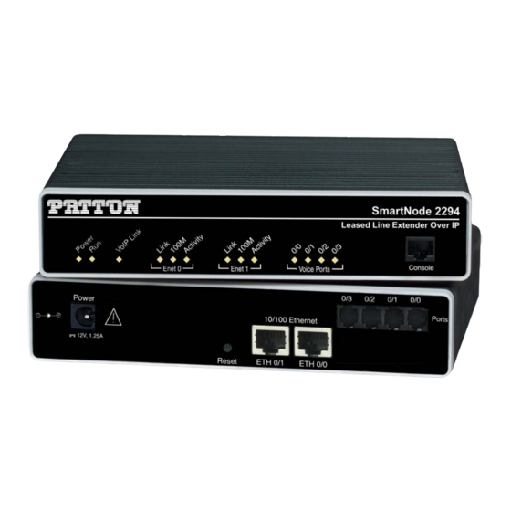
Quality of Service for up to 4 transparent voice channels and FAX calls over any IP or PSTN network. Leverage low-cost IP services with packet-voice for complete branch office voice and data connectivity. Figure 1. SmartNode extender (SmartNode 2294 shown) The SmartNode 2292 and 2294 Leased-Line Extenders, equipped with two 10/100Base-T Ethernet ports pro- vide;... -
Page 16: Smartnode 2292 And 2294 Leased-Line Extenders
The following base models (each equipped with two 10/100Base-T Ethernet ports) are available: • SmartNode 2292/EUI (2 VoIP leased line channels) • SmartNode 2294/EUI (4 VoIP leased line channels) The port combinations are indicated in the extension of the model code. T he following model code conven- tions apply: •... -
Page 17: Rear Panel Ports
SmartNode Series Leased-Line Extenders overview Reset ETH 0/1 ETH 0/0 power input connectors SmartNode 2294 table Table 2. Rear panel ports on page 26) that connect the extender to an figure 6 Ethernet device (e.g., a cable or DSL modem, LAN hub or switch). - Page 18 Enet 0 o le r ts SmartNode 2292 and 2294 “LEDs status and monitor- 1 • General information SmartNode 2292 Leased-Line Extender Over IP Console Enet 1 Ports SmartNode 2294 Leased-Line Extender Over IP Console Enet 1 Ports front panels...
-
Page 19: Applications Overview
Chapter 2 Applications overview Chapter contents Typical application ...20 Leased-line extension ...20... -
Page 20: Typical Application
Model 2292 & 2294 Series Getting Started Guide 2 • Applications overview Typical application Leased-line extension The SmartNode 2292 and 2294 Series Leased-Line Extenders allow you to save big on leased line costs. Using only one extender on each side, audio information on up to four leased-lines can be transported over a packet- based network. -
Page 21: Hardware Installation
Chapter 3 Hardware installation Chapter contents Planning the installation ...22 Installation checklist ...23 Site log ...24 Network information ...24 Network Diagram ...24 IP related information ...24 Software tools ...24 Power source ...24 Location and mounting requirements Installing the SmartNode extender Mounting the SmartNode extender Connecting cables ...25... -
Page 22: Planning The Installation
Model 2292 & 2294 Series Getting Started Guide Planning the installation Before you start the actual installation, it is strongly recommended that you gather all the information needed to install and setup the device. See carry out. Having carried out the pre-installation checks enables you to install and set up your SmartNode extender into an existing infrastructure with confidence. -
Page 23: Installation Checklist
Model 2292 & 2294 Series Getting Started Guide Installation checklist The installation checklist (see table Make a copy of this checklist and mark the entries as you complete each task. For each SmartNode 2292 or 2294 Series extender, include a copy of the completed checklist in your site log. Network information available &... -
Page 24: Site Log
Model 2292 & 2294 Series Getting Started Guide Site log Patton recommends that you maintain a site log to record all actions relevant to the system, if you do not already keep such a log. Site log entries should include information such as listed in Entry Installation Upgrades and maintenance... -
Page 25: Location And Mounting Requirements
Model 2292 & 2294 Series Getting Started Guide Location and mounting requirements The SmartNode extender is intended to be placed on a desktop or similar sturdy, flat surface that offers easy access to the cables. Allow sufficient space at the rear of the chassis for cable connections. Additionally, you should consider the need to access the unit for future upgrades and maintenance. -
Page 26: Rear View Showing Location Of Ethernet Connectors And Voice Ports (Smartnode 2294 Shown)
ETH 0/1 ETH 0/0 .2 5 0 /1 0 /0 r ts Figure 6. Rear view showing location of Ethernet connectors and voice ports (SmartNode 2294 shown) . 2 5 0 / 1 0 / 0 r t s RJ-11, male RJ-11, male Figure 7. -
Page 27: Analog Connection
Model 2292 & 2294 Series Getting Started Guide . 2 5 0 / 1 0 / 0 RJ-11, male Note Unit must not connect directly to telecom network voltage (TNV). Installing the SmartNode extender r t s Figure 8. Analog connection r IP o le rt s... -
Page 28: Connecting A Smartnode 2294 Series Device To A Hub
6 for port pin-out listing) via a cable terminated with RJ-45 plugs. Because the SmartNode 2294 Series does not have the MDX feature, a cross-over cable is required when connecting SmartNode 2294 Series devices to a host (see figure 11 Table 6. -
Page 29: Connecting To A Host
Model 2292 & 2294 Series Getting Started Guide . 2 5 0 / 1 0 / 0 RJ-45, male Twisted pair 1 Twisted pair 2 Installing the SmartNode extender r t s Cross-over cable Figure 11. Connecting to a host 3 •... -
Page 30: Power Connector Location On Rear Panel
Model 2292 & 2294 Series Getting Started Guide Connecting to external power source The extender comes with an external power supply. This section describes installing the power cord into the extender. Do the following: Note Do not connect the power cord to the power outlet at this time. 1. -
Page 31: Smartnode Extender Front Panel Leds And Console Port Locations (Smartnode 2294 Shown)
Model 2292 & 2294 Series Getting Started Guide Power Figure 13. SmartNode extender front panel LEDs and Console port locations (SmartNode 2294 shown) 4. Verify that the green Power LED is lit (see Congratulations, you have finished installing the SmartNode extender! Now go to chapter 4, with the SmartNode”... -
Page 32: Getting Started With The Smartnode
Chapter 4 Getting started with the SmartNode Chapter contents Introduction ...33 Configure the IP address...34 Power connection and default configuration Connect with the serial interface Login ...35 ...34 ...34... -
Page 33: Introduction
Model 2292 & 2294 Series Getting Started Guide Introduction This chapter leads you through the basic steps to set up a new SmartNode and to download a configuration. Patton SmartNodes can be used for a wide variety of IP-based network applications. To support and ease the configuration of the SmartNodes configuration, templates for the most important applications are available on the Patton server at www.patton.com/voip. -
Page 34: Configure The Ip Address
Model 2292 & 2294 Series Getting Started Guide Configure the IP address Power connection and default configuration First the SmartNode must be connected to the mains power supply with the power cable. Wait until the 'Run' LED stops blinking and lights constantly. Now the SmartNode is ready. The factory default configuration for the Ethernet interface IP addresses and network masks are listed in Table 7. -
Page 35: Login
Model 2292 & 2294 Series Getting Started Guide Login 1. Accessing your SmartNode via the local console port (or via a Telnet session) causes the login screen to dis- play. Type the factory default login: administrator and leave the password empty. Press the Enter key after the password prompt. -
Page 36: Leds Status And Monitoring
Chapter 5 LEDs status and monitoring Chapter contents Status LEDs...37... -
Page 37: Status Leds
Activity Link Link Activity Table 8. SmartNode LED Indications Description 5 • LEDs status and monitoring Figure 16 shows SmartNode 2292 and o le SmartNode 2294 Leased-Line Extender Over IP Console Voice Port 0/3 Voice Console Voice port Port 0/2... -
Page 38: Contacting Patton For Assistance
Chapter 6 Contacting Patton for assistance Chapter contents Introduction ...39 Contact information...39 Warranty Service and Returned Merchandise Authorizations Warranty coverage ...39 Out-of-warranty service Returns for credit ...39 Return for credit policy RMA numbers ...40 Shipping instructions (RMAs)...39 ...39 ...40 ...40... -
Page 39: Introduction
Model 2292 & 2294 Series Getting Started Guide Introduction This chapter contains the following information: • “Contact information”—describes how to contact Patton technical support for assistance. • “Warranty Service and Returned Merchandise Authorizations RAS warranty and obtaining a return merchandise authorization (RMA). Contact information Patton Electronics offers a wide array of free technical services. -
Page 40: Rma Numbers
Model 2292 & 2294 Series Getting Started Guide Return for credit policy • Less than 30 days: No Charge. Your credit will be issued upon receipt and inspection of the equipment. • 30 to 60 days: We will add a 20% restocking charge (crediting your account with 80% of the purchase price). •... - Page 41 Appendix A Compliance information Chapter contents Compliance ...42 ...42 Safety ...42 CE Declaration of Conformity ...42...
-
Page 42: A Compliance Information
Model 2292 & 2294 Series Getting Started Guide Compliance • EN55022, Class A • EN55024 Safety • EN60950 CE Declaration of Conformity This equipment conforms to the requirements of Council Directive 1999/5/EC on the approximation of the laws of the member states relating to Radio and Telecommunication Terminal Equipment and the mutual rec- ognition of their conformity. - Page 43 Appendix B Specifications Chapter contents Capacity ...44 Audio connectivity ...44 Data Services ...44 Quality of Service ...44 Voice Signaling...44 Voice Processing...45 Management ...45 System ...45 Temperature...45 Humidity ...45...
-
Page 44: B Specifications
Model 2292 & 2294 Series Getting Started Guide B • Specifications Capacity 2 audio lines (2292) 4 audio lines (2294) Audio connectivity 2-wire RJ-11 Bandwidth 4kHz, Impedance 600-ohm Narrow Band FXS style hybrid transmit/receive Data Services Two 10/100 Ethernet ports Complete IP access router DHCP Client &... -
Page 45: Voice Processing
Model 2292 & 2294 Series Getting Started Guide B • Specifications Voice Processing CODEC G.711 a-law/mu-law, G.723, G.729ab, G.726, G.727. T.38 fax relay (9.6 k, 14.4k) G.711 transparent fax and bypass Management Web/HTTP, CLI with local console and remote Telnet access TFTP configuration &... - Page 46 Appendix C Cabling Chapter contents Introduction ...47 Serial console ...47 Ethernet 10Base-T and 100Base-T Analog FXS ...49 ...48...
-
Page 47: C Cabling
Model 2292 & 2294 Series Getting Started Guide Introduction This section provides information on the cables used to connect the SmartNode and the interface cards to the existing network infrastructure and to third party products. Serial console The SmartNode can be connected to a serial terminal over its serial console port, as depicted in Note See section “Console port”... -
Page 48: Ethernet 10Base-T And 100Base-T
Model 2292 & 2294 Series Getting Started Guide Ethernet 10Base-T and 100Base-T Ethernet devices (10Base-T/100Base-T) are connected to the SmartNode over a cable with RJ-45 plugs. Use a cross-over cable to a host, or a straight cable to a hub. See the different connections. -
Page 49: Analog Fxs
Model 2292 & 2294 Series Getting Started Guide . 2 5 0 / 1 0 / 0 RJ-45, male Analog FXS Applicable to SmartNodes equipped with FXS ports. The FXS ports are connected to analog terminals (phones, fax machines, answering machines) via cables terminated with RJ-11 connectors (see section port”... - Page 50 Appendix D Port pin-outs Chapter contents Introduction ...51 Console port...51 Ethernet 10Base-T and 100Base-T Voice port...51 port...51...
-
Page 51: D Port Pin-Outs
Model 2292 & 2294 Series Getting Started Guide Introduction This section provides pin-out information for the ports of the SmartNode. Console port Note Pins not listed are not used. Ethernet 10Base-T and 100Base-T port Note Pins not listed are not used. Voice port The voice ports use an RJ-11 connector with 6 positions. -
Page 52: Installation Checklist
Appendix E Installation checklist Chapter contents Introduction ...53... -
Page 53: Introduction
Model 2292 & 2294 Series Getting Started Guide Introduction This appendix lists the tasks for installing a SmartNode 2292 or 2294 Series extender (see copy of this checklist and mark the entries as you complete each task. For each SmartNode 2292 or 2294 Series extender, include a copy of the completed checklist in your site log.