Kärcher HD 10/25 S Service Manual
Hide thumbs
Also See for HD 10/25 S:
- User manual (77 pages) ,
- Operating manual (44 pages) ,
- Operating instructions manual (17 pages)
Table of Contents
Advertisement
Quick Links
Advertisement
Table of Contents

Related Manuals for Kärcher HD 10/25 S


Summary of Contents for Kärcher HD 10/25 S
- Page 1 HD 10/25 S HD 13/18 S Service Manual English 5.905-945.0 Rev. 00 (06/15)
-
Page 2: Table Of Contents
Contents Preface Safety instructions Hazard levels Technical Features Drive Pump Detergent system Electrical system Electronics system Other features Field of application Type plate Parts of the system Front view View from behind View from below Front view (without cover) Front view (electric box opened) Function Motor/pump unit Water filter... -
Page 3: Preface
Preface Good service work requires extensive and practice-orient- ed training as well as well-structured training materials. Hence we offer regular basic and advanced training pro- grammes covering the entire product range for all service engineers. In addition to this, we also prepare service manuals for im- portant appliances - these can be initially used as instruc- tion guides and later on as reference guides. -
Page 4: Technical Features
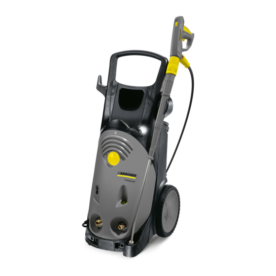
Their compact and vertical design allows easy handling and space-saving storage. Drive 4-pin, electro mo- Cooling Voltage/cur- rent type HD 10/25 S/SX Water-cooled 1500 400 V / 3~ / 50 Hz HD 13/18 S/SX Water-cooled 1500 400 V / 3~ /... -
Page 5: Field Of Application
Field of application This service manual describes the following appliances: Appliance type Appliance no. HD 10/25 S 1.286-120.0 HD 10/25 SX 1.286-500.0 HD 13/18 S 1.292-100.0 HD 13/18 SX 1.292-500.0 Type plate The type plate is located on the rear of the appliance. -
Page 6: Parts Of The System
Parts of the system Front view Mains plug 11 Lock trigger gun Mains connection 12 Trigger gun Water connection 13 Lever for trigger gun Oil level indicator 14 High pressure hose Power switch Q1/S1 15 Spray lance Operating display (LED) 16 Manometer Screw of the cover 17 High pressure connection... -
Page 7: View From Behind
View from behind Unit without hose drum 1 Storage, power cord 2 Storage dirt grinder 3 Storage triple nozzle 4 Kick plate to tilt the appliance 5 Wheel 6 Storage compartment for accessories 7 Detergent tank lid Dosing valve 8 Transport handle English 5.905-945.0 Rev. -
Page 8: View From Below
Device with hose drum 1 Crank, hose drum 2 Hose drum 3 Storage dirt grinder 4 Storage triple nozzle 5 Wheel 6 Kick plate to tilt the appliance 7 Storage compartment for accessories 8 Detergent tank lid Dosing valve 9 Transport handle View from below Unit without hose drum 1 Rubber feet... -
Page 9: Front View (Without Cover)
Device with hose drum 1 Rubber feet 2 Screw plug pressure retaining valve 3 Locking screw for pressure valve 4 Pressure switch 5 Lid of water supply 6 Pump head 7 Mains connection 8 High pressure hose Front view (without cover) Unit without hose drum Motor Manometer... -
Page 10: Front View (Electric Box Opened)
Device with hose drum High-pressure hose from the pump to the hose reel Motor Manometer Detergent connection with check valve Detergent injector Bypass valve Duct high-pressure hose Overflow valve Water connection 10 Mains connection 11 Water filter 12 Oil tank 13 Oil container lid 14 Electronics system 15 Power switch... -
Page 11: Function
Function Motor/pump unit 1 Motor bearing 13 Suction valve 2 Motor cover 14 Pressure valve 3 Motor shaft 15 Locking screw for pressure valve 4 Water cooling 16 High pressure seal 5 Stator 17 Low pressure seal 6 Rotor 18 Oil seal 7 Shaft seal ring 19 Plunger 8 Fitting key... -
Page 12: Pump Diagram
Pump diagram Trigger gun and servopress rotary regulator opened: When the power press regulator is opened all the way, the Manometer water flows from the pressure room through the pressure Pressure holding valve holding valve via the control pressure injector to the high Pressure switch pressure outlet. - Page 13 Servopress rotary regulator partially closed: With the power press regulator partially closed, the pres- 1 Manometer sure in the pressure room will not rise any further. Howev- 2 Pressure holding valve er, due to less water volume, the effect of the control 3 Pressure switch pressure injector decreases, so that the pressure in the 4 Connecting boring to overflow valve...
- Page 14 Trigger gun closed: Upon closing the trigger gun, the pressure in the pressure Manometer room rises abruptly. This pressure peak will affect the pis- Pressure holding valve ton rod and the pressure switch via the connecting boring. Pressure switch The ball is pressed out of its seat by the piston road and Connecting boring to overflow valve the entire flow volume can flow to the suction room via the Overflow valve ball...
-
Page 15: Hand Spraygun
Hand spraygun 1 Lock trigger gun 2 Casing shell 3 Hand lever 4 High pressure hose 5 Hose guide 6 Safety clip 7 Needle bearing 8 Coupling high-pressure hose/trigger gun 9 O ring 10 Node piece Function When the manual lever is actuated, the valve in the node piece opens and the water can flow from the hose through the gun into the spray lance. -
Page 16: Pressure And Volume Regulation
Pressure and volume regulation 1 Connection trigger gun 2 Connecting pin 3 Ceramic disc on gun side 4 Ceramic disc on spray pipe side 5 Casing of rotating regulator 6 Handle of rotary regulator 7 Spray lance connection The pressure and volume regulation is designed as a rota- ry regulator between the trigger gun and the spray lance. -
Page 17: Triple Nozzle
Triple nozzle A Position point jet B Initial position C Position flat stream Function The triple nozzle has two adjustable positions. By rotating the nozzle head, you can switch between the chemicals nozzle (low pressure) and the high-pressure nozzles. The selection between spotlight nozzle and the flat jet noz- zle is done by turning the spray lance while the hand lever of the trigger gun is released. -
Page 18: Electronics System
Electronics system The device is equipped with a control and monitoring elec- tronic system that monitors a number of functions. 6.7.1 Pump monitoring In case of a continuous operation or a continuous break of 30 minutes, the immediate switch-off and locking of the de- vice takes place. -
Page 19: Reset
6.7.5 Reset The resetting of the system in case of faults takes place by switching on and off the power switch. 6.7.6 Setting the DIP switches 1 1-phase device 3-phase device 2 Do not use No after run of the pump 3 Leakage monitoring No monitoring 4 30 minutes switch-off continuous operation / continu-... -
Page 20: Bypass Valve
Bypass valve Device with hose drum Function Position Description The bypass valve is to keep the pressure loss at a mini- Detergent fitting 12 - 15 mum in high pressure operation. Sphere In high pressure operation, the piston opens against the Screw spring spring force of the pressure spring and lets the water flow Screwed sealing plug... -
Page 21: Basic Settings And Service Procedures
Basic settings and service procedures DANGER Prior to all work on the appliance, switch off the appliance and pull the power plug. Shut off water supply. Drain off water pressure. Adjusting the overflow valve 1 Overflow valve spindle with hexagon 2 Counter-nut 3 Rating nut 4 Spring... -
Page 22: Hose Drum
Hose drum Device with hose drum 7.4.1 Remove the hose drum 1 High pressure hose 2 Safety clip 3 Node piece Pull out the safety clip. Pull the high-pressure hose off the connection piece. 1 Screws 2 Hose drum ... -
Page 23: Replace The Seal Of The Rotary Grommet
1 high pressure hose 2 Washers 3 High pressure outlet Pull the high pressure hose out of the high pressure outlet. 7.4.3 Replace the seal of the rotary grommet 1 Crank Remove the crank from the hose reel straightly. 1 Holder hose reel 2 Screws 3 Hose drum... - Page 24 1 Seal screw 2 Node piece 3 Axle 4 O rings Remove O-rings. Check axle and connection piece for signs of wear. Installation information Replace the O-rings. Grease the O-rings. Grease 6.288-088.0 English 5.905-945.0 Rev. 00 (06/15)
-
Page 25: Troubleshooting
Troubleshooting Findings Possible cause Correction Appliance is not running Power supply interrupted Check connection cable for damages. Check mains fuses and mains voltage Disturbances in the electrical sys- Check / replace transformer. Check/replace the fuse. Check thermal motor protection switch. Check / replace the contactor. -
Page 26: Technical Documentation
Technical Documentation Appliance type Appliance Circuit diagram Operating instructions Maintenance Spare parts list HD 10/25 S EU I 1.286-120.0 0.090-000.0 5.964-882.0 5.950-582.0 5.971-980.0 400 V / 3~ / 50 Hz HD 10/25 SX EU I 1.286-500.0 0.090-000.0 5.964-882.0 5.950-582.0 5.972-135.0... -
Page 27: Special Tools
Special tools Electric measuring appliance 6.803-022.0 Shut-off valve with thermometer 2.901-030.0 Puller for swashing plate 4.901-038.0 Installation mandrel oil seal, high-pressure 5.901-055.0 seal Piston diameter 20mm Installation sleeve, high pressure seal 5.901-136.0 Piston diameter 20 mm and 22 mm Installation mandrel high pressure gasket 5.901-064.0 Piston diameter 22mm Installation mandrel oil sealing ring... - Page 28 Test manometer for working pressure 4.742-025.0 Installation and removal tools, overflow valve 4.901-054.0 seat Removal pliers, pressure/suction valves 4.901-062.0 and water sieves English 5.905-945.0 Rev. 00 (06/15)
-
Page 29: Circuit Diagram
Circuit diagram When working on the device, please always use the cur- rent circuit diagram in DISIS. Control chip Pressure switch Operating display (LED) Fuse Contactor Motor Q1/S1 Power switch Pressure switch Transformer WS_M1 Winding protection contact English 5.905-945.0 Rev. 00 (06/15) -
Page 30: Torques
Torques Name Cylinder head screws 50 - 60 Piston casing 5 - 7 Trigger gun, pressure regulator Screw connection pressure valves 40 - 45 Screw connection pressure switch 15 - 17 Screw connection suction valves 5 - 8 Overflow valve seat 8 - 10 Swash plate 12 + 3...