
Related Manuals for Patton electronics 2156


Summary of Contents for Patton electronics 2156
- Page 1 Part# 07M2156_2157 Doc# 032131U Rev. A Revised 2/4/03 An ISO-9001Certified Company USER MANUAL MODELS 2156 & 2157 CopperLink Ethernet Extenders SALES OFFICE (301) 975-1000 TECHNICAL SUPPORT (301) 975-1007...
-
Page 2: Table Of Contents
A.7 Environmental ... 17 A.8 Dimensions ... 17 Models 2156 and 2157 Series Factory Replacement Parts and Accessories... 18 Models 2156 and 2157 Series Interface Pin Assignment ... 19 C.1 10/100Base-T Interface ... 19 RJ-45 ... 19 C.2 CopperLink Interface ... 19... -
Page 3: Warranty Information
However, there is no guarantee that interference will not occur in a particular installation. If the Model 2156 or 2157 does cause interference to radio or television reception, which can be deter-... -
Page 4: Fcc Part 68
Caution 1. You are required to request service from the telephone company before you connect the Model 2156 or 2157 to a network. When you request service, you must provide the telephone company with the following data. -
Page 5: Industry Canada Notice
1.4 INDUSTRY CANADA NOTICE NOTICE: This equipment meets the applicable Industry Canada Termi- nal Equipment Technical Specifications. This is confirmed by the registra- tion number. The abbreviation , before the registration number signifies that registration was performed based on a Declaration of conformity indicating that Industry Canada technical specifications were met. -
Page 6: General Information
• Auto-rate adaption ensures the highest rate possible for each exten- sion distance • Data rates to 2.3 Mbps (for Model 2156) and 4.6 Mbps (for Model 2157) • Auto-sensing 10/100Base-T • Extends network connections up to 30,000 ft (9,144 m) over 2-wire 24- AWG unconditioned lines (see Appendix A on page 15) •... - Page 7 Figure 1. Typical application The 2157/L and 2157/R work together to create a transparent extension between two peered Ethernet LANs. Figure 1 shows a typical point-to- point application.
-
Page 8: Installation
Ethernet LAN sites over a distance greater than 30,000 ft (9,144 m) over 24 AWG (0.5 mm) twisted-pair wire. Note The Models 2156 and 2157 use an auto-rate adaption feature to provide the fastest data rate possible over the wire and distance of each Ethernet extension. The actual distance and rate achieved for Ethernet extension may vary depending on the environment and type/gauge of the wire used. -
Page 9: Line Interface-Connecting The 10/100Base-Tethernet Interface
Follow the steps below to connect the CopperLink interfaces. Note The Model 2156 or 2157 units work in pairs. One of the units must be a Model 2156/L (local) or 2157/L, and the other unit must be a Model 2156/R (remote) or 2157/R. -
Page 10: Connecting The 10/100Base-T Ethernet Port To A Hub Or Pc
Figure 4. CopperLink Ethernet Extender 10/100Base-T RJ-45 Connector Pinout. Connecting the 10/100Base-T Ethernet Port to a Hub or PC The Models 2156 and 2157 are equipped with an MDI-X switch that enables connections to a hub (DCE) or PC (DTE) interface, thereby elimininating confusion over whether a straight-through or crossover cable is needed. -
Page 11: Connecting Power
3.3 CONNECTING POWER An external AC or DC power supply is available separately. This connec- tion is made via the barrel jack on the rear panel of the Models 2156 and 2157. No configuration is necessary for the power supply (See Appendix B on page 18 for domestic and international power supply and cord options). -
Page 12: External 48 Vdc Power Supply
An approved external power supply that incorporates a disconnect device must be used and positioned within easy reach of the operator’s position. Caution Connect the equipment to a 5 VDC source that is electri- cally isolated from the AC source. The 5 VDC source is to be reliably connected to earth. -
Page 13: Console Port
3.5 CONSOLE PORT The Console Port is only intended for use by Patton Electronics Technical Support technicians. -
Page 14: Operation
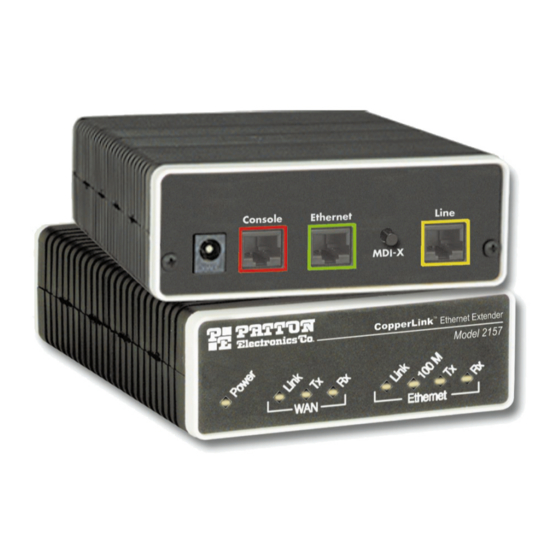
LED status monitors. 4.1 FRONT PANEL LED STATUS MONITORS The Models 2156 and 2157 feature eight front-panel LEDs that monitor power, Ethernet signals, and the CopperLink connection. Figure 9 shows the front panel location of each LED. Table 1 describes the LED functions. -
Page 15: Specifications
• Convenient and standard RJ connectors for Ethernet and line • External UI or 48 VDC power supply options • Standard 1-year warranty A.2 WAN CHARACTERISTICS • 2.3 Mbps (Model 2156) or 4.6 Mbps speed (Model 2157) • RJ-11 connector • Uses two-wire unconditioned twisted-pair A.3 ETHERNET •... -
Page 16: Extension Distance And Rate
A.4 EXTENSION DISTANCE AND RATE • 2.3 Mbps (Model 2156) or 4.6 Mbps speed (Model 2157) • Distances up to 30,000 ft (9,144 m) on 24 AWG (0.4 mm) wire • Auto-adjusting rate picks best rate for a given extension distance (see... -
Page 17: Led Indicators
A.5 LED INDICATORS • Eight LED indicators • Power • WAN Link, Transmit, and Receive • Ethernet Link, 100M, Transmit, and Receive A.6 POWER AND POWER SUPPLY SPECIFICATIONS • Either AC or DC options are available • Connection to the CopperLink Ethernet Extender requires +5VDC ±5% DC power (1.0A minimum). -
Page 18: Models 2156 And 2157 Series Factory Replacement Parts And Accessories
MODELS 2156 AND 2157 SERIES FACTORY REPLACEMENT PARTS AND ACCESSORIES Patton Model # 2156 Base Models 2156/L CopperLink Ethernet Extender; Line: RJ-11 (Local) 2156/R CopperLink Ethernet Extender; Line: RJ-11 (Remote) 2156-2PK CopperLink Ethernet Extender Kit: includes one local (L) and... -
Page 19: Models 2156 And 2157 Series Interface Pin Assignment
APPENDIX C MODELS 2156 AND 2157 SERIES INTERFACE PIN ASSIGNMENT C.1 10/100BASE-T INTERFACE RJ-45 • Pin 1: TX+ • Pin 2: TX- • Pin 3: RX+ • Pin 6: RX- • Pins 4, 5, 7, 8: no connection C.2 COPPERLINK INTERFACE RJ-11 •... - Page 20 Notes ________________________________________________________ ________________________________________________________ ________________________________________________________ ________________________________________________________ ________________________________________________________ ________________________________________________________ ________________________________________________________ ________________________________________________________ ________________________________________________________ ________________________________________________________ ________________________________________________________ ________________________________________________________ ________________________________________________________ ________________________________________________________ ________________________________________________________ ________________________________________________________ ________________________________________________________ ________________________________________________________ ________________________________________________________ ________________________________________________________ ________________________________________________________ Copyright © 2002 Patton Electronics Company All Rights Reserved.