Table of Contents
Advertisement
Quick Links
Advertisement
Table of Contents
Troubleshooting

Related Manuals for Toyota 22R-E


Summary of Contents for Toyota 22R-E
- Page 1 IN–1 INTRODUCTION – INTRODUCTION...
-
Page 2: How To Use This Manual
IN–2 INTRODUCTION – HOW TO USE THIS MANUAL HOW TO USE THIS MANUAL INDEX An INDEX is provided on the first page of each section to guide you to the item to be repaired. To assist you in finding your way through the manual, the Section Title and major heading are given at the top of every page. -
Page 3: Specifications
IN–3 INTRODUCTION – HOW TO USE THIS MANUAL The procedures are presented in a step–by–step format: Example: The illustration shows what to do and where to do it. The task heading tells what to do. The detailed text tells how to perform the task and gives other information such as specifications and warnings. -
Page 4: Engine Serial Number
IN–4 INTRODUCTION – IDENTIFICATION INFORMATION CAUTIONS, NOTICES, HINTS: CAUTIONS are presented in bold type, and indicate there is a possibility of injury to you or other people. NOTICES are also presented in bold type, and indicate the possibility of damage to the components being repaired. - Page 5 IN–5 INTRODUCTION – GENERAL REPAIR INSTRUCTIONS GENERAL REPAIR INSTRUCTIONS 1. Use fender, seat and floor covers to keep the vehicle clean and prevent damage. 2. During disassembly, keep parts in the appropriate order to facilitate reassembly. 3. Observe the following: (a) Before performing electrical work, disconnect.
- Page 6 IN–6 INTRODUCTION – GENERAL REPAIR INSTRUCTIONS (b) When reusing precoated parts, clean off the old adhesive and dry with compressed air. Then apply the specified seal lock adhesive to the bolt, nut or threads. (c) Precoated parts are indicated in the component illustrations by the ”*”...
- Page 7 IN–7 INTRODUCTION – GENERAL REPAIR INSTRUCTIONS 11. Care must be taken when jacking up and supporting the vehicle. Be sure to lift and support the vehicle at the proper locations (See page IN–9). (a) If the vehicle is to be jacked up only at the front or rear end, be sure to block the wheels at the opposite end in order to ensure safety.
- Page 8 IN–8 INTRODUCTION – PRECAUTION PRECAUTION FOR VEHICLES EQUIPPED WITH A CATALYTIC CONVERTER CAUTION: If large amounts of unburned gasoline flow into the converter, it may overheat and create a fire hazard. To prevent this, observe the following precautions and explain them to your customer. 1.
- Page 9 IN–9 INTRODUCTION – VEHICLE LIFT AND SUPPORT LOCATIONS VEHICLE LIFT AND SUPPORT LOCATIONS...
- Page 10 IN–10 INTRODUCTION – ABBREVIATIONS USED IN THIS MANUAL ABBREVIATIONS USED IN THIS MANUAL Automatic Disconnecting Differential Automatic Locking Retractor Automatic Transmission Automatic Transmission Fluid Before Top Dead Center BTDC California Calif. Circuit Breaker Cab and Chassis C&C Dash Pot Double Rear Wheel Electronic Control Unit Emergency Locking Retractor Electronic Spark Advance...
- Page 11 IN–11 INTRODUCTION – ABBREVIATIONS USED IN THIS MANUAL Toyota Computer Controlled System TCCS Top Dead Center TEMP. Temperature Transmission Undersize Vacuum Control Valve Vacuum Switching Valve Vacuum Transmitting Valve With Without Two Wheel Drive Vehicles (4 x 2) Four Wheel Drive Vehicles (4 x 4)
- Page 12 GLOSSARY OF SAE AND TOYOTA TERMS GLOSSARY OF SAE AND TOYOTA TERMS M076–03 This glossary lists all SAE–J 1930 terms and abbreviations used in this manual in compliance with SAE recommendations, as well as their Toyota equivalents. TOYOTA TERMS SAE ABBRE– SAE TERMS ( )––ABBREVIATIONS...
- Page 13 IN–13 INTRODUCTION – GLOSSARY OF SAE AND TOYOTA TERMS Idle Speed Control (ISC) Idle Air Control Intake or Inlet Air Temperature Intake Air Temperature I AT Ignition Control Module Indirect injection Indirect Fuel Injection Inertia Fuel–Shutoff Idle Speed Control Knock Sensor...
- Page 14 IN–14 INTRODUCTION – GLOSSARY OF SAE AND TOYOTA TERMS Bimetal Vacuum Switching Valve (BVSV) Thermal Vacuum Valve Thermostatic Vacuum Switching Valve (TVSV) Three–Way Catalyst (TWC) Three–Way Catalytic Converter CCRO Three–Way + Oxidation Catalytic Converter TWC+OC + CCo Volume Air Flow...
- Page 15 IN–15 INTRODUCTION – STANDARD BOLT TORQUE SPECIFICATIONS STANDARD BOLT TORQUE SPECIFICATIONS HOW TO DETERMINE BOLT STRENGTH Class Class Mark Mark 4– Stud bolt Hexagon 5– head bolt 6– 8– 9– 10– 11– No mark Hexagon flange bolt w/ washer No mark hexagon bolt Hexagon head bolt...
- Page 16 IN–16 INTRODUCTION – STANDARD BOLT TORQUE SPECIFICATIONS SPECIFIED TORQUE FOR STANDARD BOLTS Specified torque Diameter Pitch Class 1 OT...
- Page 17 MA–6 MAINTENANCE – MAINTENANCE OPERATIONS MAINTENANCE OPERATIONS ENGINE Cold Engine Operations 1. (3VZ–E ENGINE) REPLACE TIMING BELT (a) Remove the timing belt. (See pages EG–32) (b) Install the timing belt. (See pages EG–41) 2. INSPECT DRIVE BELTS (a) Visually check the belt for excessive wear, frayed cords etc.
- Page 18 MA–7 MAINTENANCE – MAINTENANCE OPERATIONS HINT: ”New belt” refers to a belt which has been used less than 5 minutes on a running engine. ”Used belt” refers to a belt which has been used on a running engine for 5 minutes or more. After replacing the drive belt, check that it fits properly in the ribbed grooves, especially in the places difficult to see.
- Page 19 MA–8 MAINTENANCE – MAINTENANCE OPERATIONS 22 R – E w/o Oil filter change 3.8 liters (4.0 US qts, 3.3 Imp. qts) w/ Oil filter change 4.3 liters (4.5 US qts, 3.8 Imp. qts) 3VZ–E w/o Oil filter change 2WD 4.0 liters (4.2 US qts, 3.5 Imp. qts) 4WD 4.2 liters (4.4 US qts, 3.7 Imp.
- Page 20 MA–9 MAINTENANCE – MAINTENANCE OPERATIONS 8. INSPECT CHARCOAL CANISTER (a) Remove charcoal canister. HINT:Label hoses for correct installation. (b) Visually inspect canister case. (c) Check for clogged filter and stuck check valve. (1) Using low compressed air (4.71 kPa (48 gf/cm2, 0.68 psi), blow into the tank pipe and check that air flows without resistance from the other pipes.
- Page 21 MA–10 MAINTENANCE – MAINTENANCE OPERATIONS 11. INSPECT EXHAUST PIPES AND MOUNTINGS Visually inspect the pipes, hangers and connections for severe corrosion, leaks or damage. 12. (3VZ–E ENGINE) ADJUST VALVE CLEARANCE (See page EG–18) 13. (FEDERAL AND CANADA) REPLACE OXYGEN SENSOR (a) Disconnect the oxygen sensor wiring connector.
- Page 22 MA–11 MAINTENANCE – MAINTENANCE OPERATIONS Hot Engine Operations 14. (22R–E ENGINE) ADJUST VALVE CLEARANCE (a) Warm up the engine to normal operating temperature. (b) Stop the engine and remove the cylinder head cover. (c) Set No.1 cylinder to TDC/compression. Turn the crankshaft with a wrench to align the timing marks at TDC.
- Page 23 MA–12 MAINTENANCE – MAINTENANCE OPERATIONS Connect all vacuum lines (i.e., EVAP, EGR system, etc.) Make sure all MFI system wiring connectors are fully connected Engine should be at normal operating tempera– ture Switch off accessories Set transmission in neutral (b) Connect a tachometer– to the engine Connect the tachometer–...
- Page 24 MA–13 MAINTENANCE – MAINTENANCE OPERATIONS Wear Deformation Cracks Corrosion Leaks Bends Twists (b) Check all clamps for tightness and connections for leakage. . (c) Check that the hoses and lines are clear of sharp edges, moving parts and the exhaust system. (d) Check that the lines installed in grommets pass thr–...
- Page 25 MA–14 MAINTENANCE – MAINTENANCE OPERATIONS (c) Check the disc for runout. Minimum disc runout: Ex. C & C 0.09 mm (0.0035 in.) C & C 0.12 mm (0.0047 in.) 18. INSPECT REAR BRAKE LININGS AND DRUMS (See BR section) (a) Check the lining – to – drum contact condition and lining wear.
- Page 26 MA–15 MAINTENANCE – MAINTENANCE OPERATIONS (b) Check the steering linkage for looseness or damage. Check that: Tie rod ends and relay rod ends do not have excessive play. Dust seals are not damaged. 20. INSPECT STEERING GEAR HOUSING Check the steering gear housing for oil leaks. If leakage is found, check for cause and repair.
- Page 27 MA–16 MAINTENANCE – MAINTENANCE OPERATIONS 23. (2WD) CHECK OIL LEVEL IN MANUAL TRANSMISSION, AUTOMATIC TRANSMISSION AND DIFFERENTIAL Remove the filler plug and feel inside the hole with your finger. Check that the oil comes to within 5 mm (0.20 in.) of the bottom edge of the hole. If the level is low, add oil until it begins to run out of the filler hole.
- Page 28 MA–17 MAINTENANCE – MAINTENANCE OPERATIONS 24. (4WD) CHECK OIL LEVEL IN MANUAL TRANSMISSION, AUTOMATIC TRANSMISSION, TRANSFER AND DIFFERENTIAL Remove the filler plug and feel inside the hole with your finger. Check that the oil comes to within 5 mm (0.20 in.) of the bottom edge of the hole. If the level is low, add oil until it begins to run out of the filler hole.
- Page 29 Above –18 _ C (0_F) SAE 90 Below –18 _ C (0 _ F) SAE 80W – 90 or 80W A.D.D. Oil grade: Toyota ’GEAR OIL SUPER’ oil or hypoid gear oil API GL–5 Viscosity: SAE 75W–90 25. REPLACE MANUAL TRANSMISSION. TRANSFER (4...
- Page 30 MA–19 MAINTENANCE – MAINTENANCE OPERATIONS Oil capacity: Transmission – W55 2.6 liters (2.7 US qts, 2.3 Imp. qts) R150 3.0 liters (3.2 US qts, 2.6 Imp. qts) G58 3.9 liters (4.1 US qts, 3.4 Imp. qts) W56 2.9 liters (3.1 US qts, 2.5 Imp. qts) RI 50F 3.0 liters (3.2 US qts, 2.6 Imp.
- Page 31 MA–20 MAINTENANCE – MAINTENANCE OPERATIONS Differential – 7.5 in. 1.35 liters (1.4 US qts, 1.2 Imp. qts) 8.0 in. 1.8 liters (1.9 US qts, 1.6 Imp. qts) Front Standard differential 1.6 liters (1.7 US qts, 1.4 Imp. qts) A.D.D. 1.86 liters (2.0 US qts, 1.6 Imp. qts) Rear 2.2 liters 2.3 US qts, 1.9 Imp.
- Page 32 MA–21 MAINTENANCE – MAINTENANCE OPERATIONS (g) Check that the fluid level is in the ”HOT” range at the normal operating temperature (70 – 80 C or 158 – 176 *F) and add as necessary. NOTICE: Do not overfill. 27. REPACK FRONT WHEEL BEARINGS AND THRUST BUSH (a) Change the front wheel bearing grease.
- Page 33 MA–22 MAINTENANCE – MAINTENANCE OPERATIONS 29. TIGHTEN BOLTS AND NUTS ON CHASSIS AND BODY Tighten the following parts: Seat mounting bolts Torque: 37 N–m (375 kgf–cm, 27 ft–lbf) Strut bar bracket–to –frame mounting bolts (2 Torque: 52 N–m (530 kgf–cm, 38 ft–Ibf) Leaf spring U –...
- Page 34 MA–23 MAINTENANCE – MAINTENANCE OPERATIONS Suspension system Fuel tank mounts Engine mounts, etc. 30. FINAL INSPECTION (a) Check operation of body parts: Hood Auxiliary catch operates properly Hood locks securely when closed Doors Door locks operate properly Doors close properly Seats Seat adjusts easily and locks securely in any positions...
- Page 35 EG1–1 ENGINE – 22R–E ENGINE...
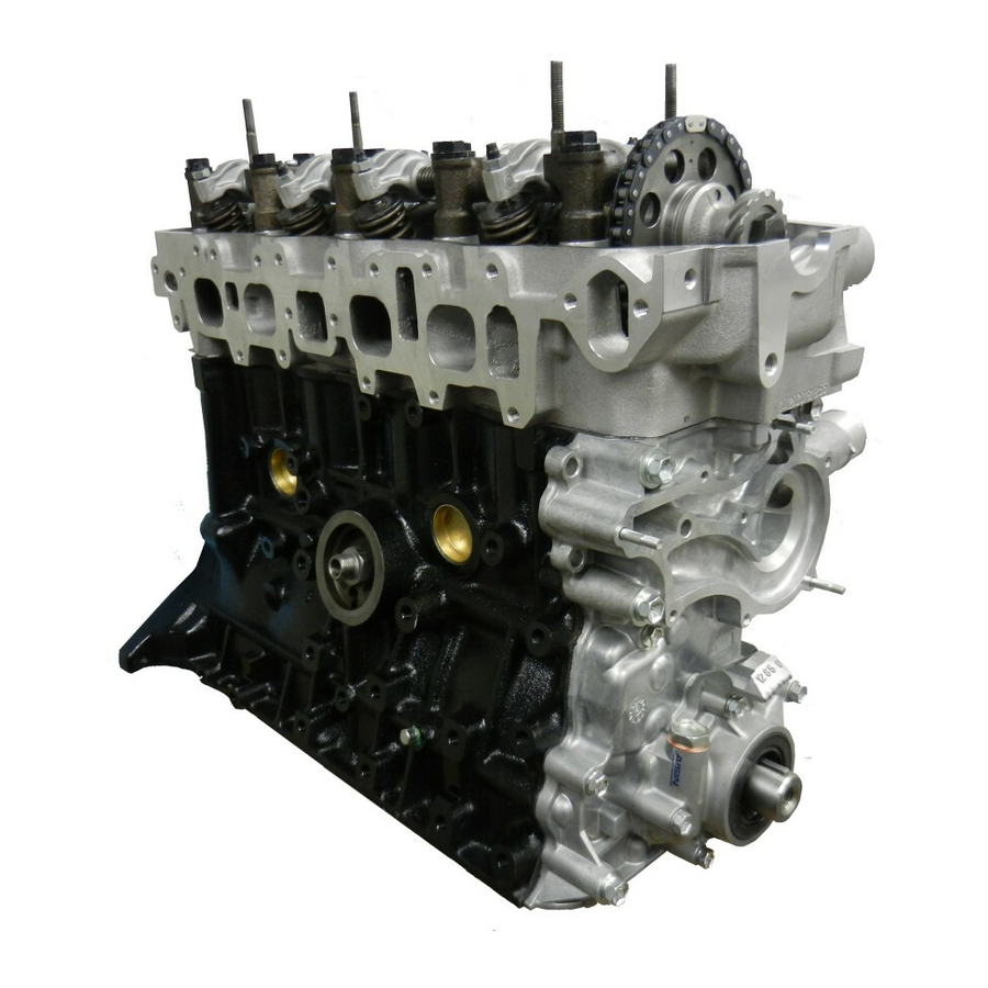
- Page 36 EG1–2 ENGINE – ENGINE MECHANICAL ENGINE MECHANICAL DESCRIPTION The 22R–E engine is an in–line 4 cylinder 2.4 liter OHC 8 valve engine.
- Page 37 EG1–3 ENGINE – ENGINE MECHANICAL The 22R–E engine is in–line 4–cylinder engine with the cylinders numbered 1–2–3–4 from the front. The crankshaft is supported by 5 bearings inside the crankcase. These bearing are made of kelmet. The crankshaft is integrated with 4 weights which are cast with it for balance. Oil holes are made in the center of the crankshaft to supply oil to the connecting rods, bearing, pistons and other components.
- Page 38 EG1–4 ENGINE – ENGINE MECHANICAL PREPARATION SST (SPECIAL SERVICE TOOLS) 09201–41020 Valve Stem Oil Seal Replacer 09201 –60011 Valve Guide Bushing Remover & Replacer 09202–43013 Valve Spring Compressor 09213–31021 Crankshaft Pulley Puller 09213–36020 Timing Gear Remover 09213–60017 Crankshaft Pulley & Gear Puller (09213–00020) Body With .Bolt (00213–00030) Handle (09213–00060) Bolt Set...
- Page 39 EG1–5 ENGINE – ENGINE MECHANICAL 09606–35014 Axle Hub & Drive Pinion Bearing Tool Set (09608–06040) Front Hub Inner Bearing Cone Replacer Crankshaft pulley 09330–00021 Companion Flange Holding Tool 09843–18020 Diagnosis Check Wire RECOMMENDED TOOLS For suspension engine 09090–04010 Engine Sling Device 09200–00010 Engine Adjust Kit Plug for the vacuum hose, fuel hose etc.
- Page 40 EG1–6 ENGINE – ENGINE MECHANICAL Dye penetrant Engine tune–up tester Heater Magnetic finger Micrometer Piston ring compressor Piston ring expander Plastigage Precision straight edge Soft brush Spring tester Valve spring Steel square Valve spring Thermometer Torque wrench Valve seat cutter Vernier calipers SSM (SERVICE SPECIAL MATERIALS) 08826–00080 Seal packing or equivalent...
- Page 41 EG1–7 ENGINE – ENGINE MECHANICAL TROUBLESHOOTING When the malfunction code is not confirmed in the diagnostic trouble code check and the problem still cannot be confirmed in the basic inspection, then proceed to this step and perform troubleshooting to the numbers in the order given in the table below. See page Suspect area Symptom...
- Page 42 EG1–8 ENGINE – ENGINE MECHANICAL See page Suspect area Symptom Engine does not crank Starter runs – engine does not crank No initial combustion No complete combustion Engine cranks slowly Under normal condition Cold engine Hot engine Incorrect first idle High engine idle speed Low engine idle speed Rough idling...
- Page 43 Thermostat EG1–228 Drive Belt section Engine Coolant Temp. Sender Gauge section Oil Pressure Switch section Generator section Cylinder Block EG1–55 EFI Main EG1–206 Relay Circuit Opening EG1–207 Relay Fuel Cut System EG1–219 Fuel Pressure EG1–210 Control System EG1–215 Fuel Quality Fuel Leakage Coolant Leakage EG1–225...
-
Page 44: Air Filter Inspection
EG1–10 ENGINE – ENGINE MECHANICAL TUNE–UP ENGINE COOLANT INSPECTION (See steps 1 and 2 on page EG1–225) ENGINE OIL INSPECTION (See steps 1 and 2 on page EG1–235) AIR FILTER INSPECTION (See step 4 on page MA–7) BATTERY INSPECTION (See CM section) HIGH–TENSION CORD INSPECTION (See page IG–6) SPARK PLUGS INSPECTION... - Page 45 EG1–11 ENGINE – ENGINE MECHANICAL HINT: Adjust idle mixture as necessary.
- Page 46 EG1–12 ENGINE – ENGINE MECHANICAL IDLE AND OR 2500 RPM CO HC CHECK HINT: This check method is used only to determine whether or not the idle and/or 2,500 rpm CO/HC complies with regulations. 1. INITIAL CONDITIONS (a) Engine at normal operating temperature (b) Air cleaner installed (c) All pipes and hoses of air intake system connected (d) All accessories switched OFF...
- Page 47 EG1–13 ENGINE – ENGINE MECHANICAL TROUBLESHOOTING If the HC/CO concentration does not comply with regulations, perform troubleshooting in the order given below. 1. Check oxygen sensor operation (See page EG1–212) 2. See the table below for possible cause, and then inspect and correct the applicable causes if neces–...
- Page 48 EG1–14 ENGINE – ENGINE MECHANICAL COMPRESSION CHECK HINT: If there is lack of power, excessive oil con– sumption or poor fuel mileage, measure the cylinder compression pressure. 1. WARM UP ENGINE 2. REMOVE SPARK PLUGS 3. DISCONNECT DISTRIBUTOR CONNECTOR 4. DISCONNECT COLD START INJECTOR CONNEC– 5.
- Page 49 EG1–15 ENGINE – ENGINE MECHANICAL CYLINDER HEAD COMPONENTS...
- Page 50 EG1–16 ENGINE – ENGINE MECHANICAL PREPARATION FOR REMOVAL 1. DISCONNECT CABLE FROM NEGATIVE TERMINAL OF BATTERY 2. DRAIN COOLANT FROM RADIATOR AND CYLIN– DER BLOCK (See step 3 on page EG1–225) 3. REMOVE INTAKE AIR CONNECTOR 4. DISCONNECT EXHAUST PIPE FROM EXHAUST MANIFOLD (a) Remove the exhaust pipe clamp.
- Page 51 EG1–17 ENGINE – ENGINE MECHANICAL 13. REMOVE EGR VACUUM MODULATOR 14. DISCONNECT FOLLOWING WIRES: (a) Cold start injector wire (b) Throttle position wire (c) (California only) EGR gas temp. sensor wire 15. REMOVE CHAMBER WITH THROTTLE BODY (a) Remove the union bolt holding the cold start injector pipe to the chamber.
-
Page 52: Cylinder Head Removal
EG1–18 ENGINE – ENGINE MECHANICAL 21. (w/PS) DISCONNECT PS BRACKET FROM CYLINDER HEAD Remove the four bolts, disconnect the ground strap and bracket. CYLINDER HEAD REMOVAL 1. REMOVE HEAD COVER (a) Remove the ground strap from the body. (b) Remove the four nuts and seals. (c) Remove the head cover. -
Page 53: Cylinder Head Disassembly
EG1–19 ENGINE – ENGINE MECHANICAL 4. REMOVE CAM SPROCKET Remove the cam sprocket and chain from the cam– shaft and leave on the vibration damper. 5. REMOVE CHARY COVER BOLT Remove the bolt in.–front of the head before the other head bolts are removed. - Page 54 EG1–20 ENGINE – ENGINE MECHANICAL 2. REMOVE INTAKE MANIFOLD WITH DELIVERY PIPE AND INJECTORS (a) Remove the two nuts and reed valve. (b) Remove the bolt and the heater inlet pipe from the cylinder head. (c) Remove the seven bolts, one hexagon bolt, two nuts and No.
- Page 55 EG1–21 ENGINE – ENGINE MECHANICAL 7. MEASURE CAMSHAFT THRUST CLEARANCE Using a dial gauge, measure the camshaft thrust clearance. Standard clearance: 0.08 – 0.18 mm (0.0031–0.0071 in.) Maximum clearance: 0.25 mm (0.0098 in.) If clearance is greater than maximum, replace the head.
- Page 56 EG1–22 ENGINE – ENGINE MECHANICAL 3. CLEAN COMBUSTION CHAMBERS Using a wire brush, remove all the carbon from the combustion chambers. NOTICE: Be careful not to scratch the head gasket con– tact surface. 4. CLEAN VALVE GUIDE BUSHINGS Using a valve guide brush and solvent, clean all the valve guide bushings.
- Page 57 EG1–23 ENGINE – ENGINE MECHANICAL 7. INSPECT CYLINDER HEAD FOR CRACKS Using a dye penetrant, check the combustion cham– bers, intake and exhaust ports, head surface and the top of the head for cracks. If a crack is found, replace the head. 8.
- Page 58 EG1–24 ENGINE – ENGINE MECHANICAL 10. IF NECESSARY, REPLACE VALVE GUIDE BUSH– INGS (a) Using a brass bar and hammer, break the valve –guide bushing. (b) Gradually heat the cylinder head to approx. 90SC (194SF). (c) Using SST and a hammer, drive out valve guide bus– hing.
- Page 59 EG1–25 ENGINE – ENGINE MECHANICAL (f) Gradually heat the cylinder head to approx. 90SC (194S F). (g) Using SST a and hammer, drive in a new valve guide bushing unit the snap ring makes contact with the cylinder head. SST 09201–6001 1 (h) Using a sharp 8 mm (0.31 mm) reamer, ream the valve guide bushing to obtain standard specified clearance (See page EG1–23) between the valve guide bushing...
- Page 60 EG1–26 ENGINE – ENGINE MECHANICAL (e) Check the valve overall length. Standard overall length: Intake 113.5 mm (4.468 in.) Exhaust 112.4 mm (4.425 in.) Minimum overall length: Intake 113.0 mm (4.449 in.) Exhaust 111.9 mm (4.406 in.) If the valve overall length is less than minimum, re– place the valve.
- Page 61 EG1–27 ENGINE – ENGINE MECHANICAL If seating is too low on the valve face, use 60S (IN) or 65S (EX) and 45S cutters to correct the seat. (d) Hand–lap the valve and valve seat with abrasive compound. 13. INSPECT VALVE SPRINGS (a) Using a steel square, measure the squareness of the valve spring.
- Page 62 EG1–28 ENGINE – ENGINE MECHANICAL 14. INSPECT CAMSHAFT AND BEARING CAPS (a) Place the cam shaft on V – blocks and , using a dial indicator, measure the circle runout at the center journal. Maximum circle runout: 0.2 mm (0.008 in.) If the circle runout is greater than maximum, replace the camshaft.
- Page 63 EG1–29 ENGINE – ENGINE MECHANICAL (e) Remove the caps and measure the Piastigage at its widest point. Standard clearance: 0.01 – 0.05 mm (0.0004 – 0.0020 in.) Maximum clearance: 0.1 mm (0.004 in.) !f clearance is greater than maximum, replace the cylinder head and/or camshaft.
-
Page 64: Cylinder Head Assembly
EG1–30 ENGINE – ENGINE MECHANICAL 17. INSPECT INTAKE, EXHAUST MANIFOLDS AND AIR INTAKE CHAMBER Using a precision straight edge and thickness gauge, check the surface contacting the cylinder head or intake manifold for warpage. Maximum intake warpage: 0.2 mm (0.008 in.) Maximum exhaust warpage: 0.7 mm (0.28 in.) Maximum air intake chamber warpage: 0.2 mm (0.008 in.) - Page 65 EG1–31 ENGINE – ENGINE MECHANICAL 1. INSTALL VALVES (a) Install a new oil seal on the valve guide bushing. HINT Pushing down at the place shown in the illus– tration. (b) Rotate the oil seal to check that it is firmly installed. (c) Lubricate and insert valve in the valve guide bushing.
- Page 66 EG1–32 ENGINE – ENGINE MECHANICAL 6. INSTALL PLUG PATE Install a new gasket and plug plate with the two bolts. HINT: Attach the flat side of the gasket to the cylinder head. 7. INSTALL EXHAUST MANIFOLD (a) Position a new gasket on the cylinder head. (b) Install the exhaust manifold with the eight nuts.
-
Page 67: Cylinder Head Installation
EG1–33 ENGINE – ENGINE MECHANICAL (c) Install the EGR valve with the two bolts and nut. 9. INSTALL INTAKE MANIFOLD (a) Position a new gasket on the cylinder head. (b) Install the intake manifold with the delivery pipe and injectors and No. 1 air pipe. (c) Install the seven bolts, one hexagon bolt and two nuts. - Page 68 EG1–34 ENGINE – ENGINE MECHANICAL (a) If the sprocket was removed, align the alignment marks placed on the sprocket and chain during re– moval. (b) position the cylinder head over dowels on the block. 3. INSTALL ROCKER ARM ASSEMBLY (a) Place the rocker arm assembly over the dowels on the cylinder head.
- Page 69 EG1–35 ENGINE – ENGINE MECHANICAL 6. ADJUST VALVE CLEARANCE (a) Set the No. 1 cylinder to TDC/compression. Turn the crankshaft with a wrench to align the timing, marks at TDC. Set the groove on the pulley at the ”0” mark position of the chain cover. Check that the rocker arms on the No.
- Page 70 EG1–36 ENGINE – ENGINE MECHANICAL 8. INSTALL HEAD COVER (a) Apply seal packing to the four locations shown. Seal packing: Part No. 08826–00080 or equivalent (b) Install the gasket to the cylinder head. (c) Place the head cover on the cylinder head and install the four seals and nuts.
- Page 71 EG1–37 ENGINE – ENGINE MECHANICAL (e) (A/T) OD temp. switch wire (f) Engine coolant temp. sender gauge wire (g) Injector wires (h) (with A/C) Compressor wires (i) Transmission wires (j) Starter wire (terminal 50) (k) Oil pressure sender gauge wire (l) Knock sensor wire 6.
- Page 72 EG1–38 ENGINE – ENGINE MECHANICAL (h) EGR vacuum modulator hose (i) EVAP hose (j) (with A/C) VSV hoses (k) (w/PS) Air control valve hoses (l) Brake booster hose (m) No. 1 and No. 2 PCV hoses 11. CONNECT GROUND STRAP TO ENGINE REAR SIDE 12.
- Page 73 EG1–39 ENGINE – ENGINE MECHANICAL TIMING CHAIN COMPONENTS PREPARATION OF REMOVAL 1. REMOVE CYLINDER HEAD (See page EG1–16) 2. REMOVE RADIATOR (See page EG1–230) 3. (4WD) REMOVE FRONT DIFFERENTIAL (See SA section) 4. REMOVE OIL PAN (a) Remove the engine undercover. (b) Remove the engine mounting bolts.
- Page 74 EG1–40 ENGINE – ENGINE MECHANICAL SST 09032 – 00100 HINT: When removing the oil pan, be careful not to damage the oil pan flange. TIMING CHAIN REMOVAL 1. (W/PS) REMOVE PS BELT 2. (with A/C) REMOVE A/C BELT, COMPRESSOR AND BRACKET 3.
- Page 75 EG1–41 ENGINE – ENGINE MECHANICAL 5. REMOVE NO. 1 WATER BY–PASS PIPE Remove the two bolts and pipe. 6. REMOVE FAN BELT ADJUSTING BAR (a) (w/ PS) Remove the bolt and PS lower bracket. (b) Remove the three bolts and bar. 7.
- Page 76 EG1–42 ENGINE – ENGINE MECHANICAL 10. REMOVE PUMP DRIVE SPLINE AND CRANKSHAFT SPROCKET If the oil pump drive spline and sprocket cannot be removed by hand, use SST to remove them together. SST 09213–36020 11. REMOVE GASKET MATERIAL ON CYLINDER BLOCK COMPONENTS INSPECTION 1.
- Page 77 EG1–43 ENGINE – ENGINE MECHANICAL TIMING CHAIN INSTALLATION (See page EG1–39) 1. INSTALL CRANKSHAFT SPROCKET AND CHAIN (a) Turn the crankshaft until the shaft key is on top. (b) Slide the sprocket over the key on the crankshaft. (c) Place the timing chain on the sprocket with the single bright chain link aligned with the timing mark on the sprocket.
- Page 78 EG1–44 ENGINE – ENGINE MECHANICAL 6. INSTALL HEATER WATER OUTLET PIPE Connect the heater water outlet pipe to the timing chain cover with the two bolts. 7. INSTALL NO.1 WATER BY–PASS PIPE Install the pipe with the two bolts. 8. INSTALL CRANKSHAFT PULLEY (a) Install the crankshaft pulley and bolt.
- Page 79 EG1–45 ENGINE – ENGINE MECHANICAL Using a razor blade and gasket scraper, remove all the packing (FIPG) material from the gasket surfaces. Thoroughly clean all components to remove all the loose material. Clean both sealing surfaces with a non–residue solvent. NOTICE: Do not use a solvent which will affect the pai–...
- Page 80 EG1–46 ENGINE – ENGINE MECHANICAL CYLINDER BLOCK COMPONENTS...
- Page 81 EG1–47 ENGINE – ENGINE MECHANICAL ENGINE REMOVAL 1. REMOVE HOOD 2. REMOVE BATTERY 3. REMOVE ENGINE UNDER COVER 4. DRAIN COOLANT FROM RADIATOR AND CYLIN– DER BLOCK (See step 3 on page EG1–225) 5. DRAIN ENGINE OIL (See step 1 on page EG1–236) 6.
- Page 82 EG1–48 ENGINE – ENGINE MECHANICAL (c) (w/Cruise control) Cruise control cable 14. (w/PS) REMOVE PS PUMP FROM BRACKET (a) Remove the drive belt. (b) Remove the four bolts. (c) Remove the PS pump. HINT: Lay the PS pump to one side without disconn– ecting the hoses.
- Page 83 EG1–49 ENGINE – ENGINE MECHANICAL (b) Remove the cross shaft from the body. 22. DISCONNECT SPEEDOMETER CABLE NOTICE: Do not lose the felt dust protector and washers. 23. (4WD) REMOVE TRANSFER UNDER COVER 24. (4WD) REMOVE STABILIZER BAR 25. (4WD) REMOVE FRONT PROPELLER SHAFT (See PR section) 26.
- Page 84 EG1–50 ENGINE – ENGINE MECHANICAL 31. (4WD) REMOVE NO.2 FRAME CROSSMEMBER FROM SIDE FRAME (a) Remove the four bolts from the engine rear mounting. (b) Raise the transmission slightly with a jack. (c) Remove the four bolts from the side frame and remove the No.2 frame crossmember.
- Page 85 EG1–51 ENGINE – ENGINE MECHANICAL 16. REMOVE OIL STRAINER Remove the four bolts, strainer and gasket. 17. REMOVE REAR OIL SEAL RETAINER Remove the five bolts, rear oil seal retainer and gasket. 18. MEASURE CONNECTING ROD THRUST CLEAR– ANCE Using a dial gauge, measure the thrust clearance. Standard clearance: 0.16 –...
- Page 86 EG1–52 ENGINE – ENGINE MECHANICAL (f) Lay a strip of Plastigage across the crankshaft pin. (g) Align the rod and cap marks and fit on the cap. Install and torque the cap nuts. Torque: 69 N–m(700 kgf–cm, 51 ft–lbf) HINT: Do not turn the crankshaft.
- Page 87 EG1–53 ENGINE – ENGINE MECHANICAL 20. PUSH OUT PISTON AND CONNECTING ROD AS– SEMBLY (a) Remove all the carbon from top of the bore to the top of the cylinder. (b) Cover the rod bolts with a short piece of hose to protect the crank pin from damage.
- Page 88 EG1–54 ENGINE – ENGINE MECHANICAL 22. MEASURE CRANKSHAFT OIL CLEARANCE (a) Gradually loosen and remove the bearing cap bolts in three passes and in numerical order shown. (b) Using the removed bearing cap bolts, pry the bearing cap fore and aft, and remove it with the lower bearing and thrust washers (No.3 journal only).
- Page 89 EG1–55 ENGINE – ENGINE MECHANICAL (i) Remove the main bearing caps. (j) Measure the Plastigage at its widest point. Standard clearance: 0.025 – 0.055 mm (0.0010 – 0.0022 in.) Maximum clearance: 0.08 mm (0.0031 in.) If the clearance is greater than maximum, replace the bearings and/or grind the main journals.
- Page 90 EG1–56 ENGINE – ENGINE MECHANICAL 3. INSPECT CYLINDERS Visually inspect cylinders for vertical scratches. If deep scratches are present, rebore all four cylinders. (See page EG1–66) 4. INSPECT CYLINDER BLOCK WARPAGE Warpage limit: 0.5 mm (0.0020 in.) If warpage is greater than specified value, replace the cylinder block.
- Page 91 EG1–57 ENGINE – ENGINE MECHANICAL Maximum diameter: STD 92.23 mm (3.6311 in.) 0/S 0.50 92.73 mm (3.6508 in.) 0/S 1.00 93.23 mm (3.6705 in.) If the diameter is greater than maximum, rebore all four cylinders, or replace the cylinder block. 6.REMOVE CYLINDER RIDGE If wear is less than 0.2 mm (0.008 in.), use a ridge reamer to machine the top of the cylinder.
- Page 92 EG1–58 ENGINE – ENGINE MECHANICAL 3. DISCONNECT CONNECTING ROD FROM PISTON (a) Using needle – nose pliers, remove the snap rings from the piston. (b) Heat the piston in hot water approx. 60SC(140SF). (c) Using a plastic–faced hammer and brass bar, lightly tap out the piston pin from the piston.
- Page 93 EG1–59 ENGINE – ENGINE MECHANICAL (b) Using a groove cleaning tool or broken ring, clean the ring grooves. (c) Using solvent and a brush, thoroughly clean the piston. NOTICE: Do not use a wire brush. 2. INSPECT PISTON DIAMETER AND OIL CLEARANCE HINT: There are three sizes of the standard piston diameter, marked ”’1”, ”2”, and ”3”, accordingly.
- Page 94 EG1–60 ENGINE – ENGINE MECHANICAL Piston diameter: STD Mark ” 91.975 – 91.985 mm (3.6211 – 3.6214 in.) Mark ”2’ 91.985 – 91.995 mm (3.6214 – 3.6218 in.) Mark ’3” 91.995 – 92.005 mm (3.6218 – 3.6222 in.) 0/S 0.50 92.475 –...
- Page 95 EG1–61 ENGINE – ENGINE MECHANICAL 4. MEASURE RING END GAP (a) Insert the piston ring into the cylinder. (b) Using a piston, push the ring a little beyond the bottom of the ring travel. (130 mm (5.12 in.) from top surface of cylinder block) (c) Using a thickness gauge, measure the end gap.
- Page 96 EG1–62 ENGINE – ENGINE MECHANICAL Cheek that the rod is not twisted. Maximum twist: 0.15 mm (0.0059 in.) per 100 mm (3.94 in.) (b) Measure the oil clearance between the rod bushing and piston pin. Using an inside dial indicator, measure the inside diameter of the rod bushing.
- Page 97 EG1–63 ENGINE – ENGINE MECHANICAL 3. HONE NEW BUSHING AND CHECK PIN FIT IN CONNECTING ROD (a) Hone the new bushing and check that the oil clear– ance is within standard specification. Standard oil clearance: 0.005 – 0.011 mm (0.0002 – 0.0004 in.) (b) Check the pin fit at the normal room temperature.
- Page 98 EG1–64 ENGINE – ENGINE MECHANICAL (a) Grind the crank pins and/or main journals to the undersized finished diameter. Bearing size (U/S 0.25) Main journal finished diameter: 59.701 – 59.711 mm (2.3504 – 2.3508 in.) Crank pin finished diameter: 52.701 – 52.711 mm (2.0748 – 2.0752 in.) (b) Install a new pin and/or main undersized bearings.
- Page 99 EG1–65 ENGINE – ENGINE MECHANICAL (c) Apply MP grease to a new oil seal lip. (d) Using SST and a hammer, tap in the oil seal until its surface is flush with the timing chain cover edge. SST 09223 – 50010 3.
-
Page 100: Piston And Connecting Rod Assembly
EG1–66 ENGINE – ENGINE MECHANICAL CYLINDERS BORING Outside Diameter Size mm 0 n. ) 1. SELECT OVERSIZED PISTON O/S pistons with pins are available in the sizes listed. 92.475 – 92.505 O/S 0. 50 (3.6407 – 3.6419) Replace pistons in matched sets. Take the largest 92.975 –... - Page 101 EG1–67 ENGINE – ENGINE MECHANICAL (c) Align the notch on the piston with the mark on the rod and push the piston pin in with your thumb. (d) Install a new snap ring on the other side of the pin. 2.
- Page 102 EG1–68 ENGINE – ENGINE MECHANICAL E61W1_0¿ INSTALLATION OF CRANKSHAFT, PISTON AND CONNECTING ROD ASSEMBLY (See page EG1–46) GENERAL ASSEMBLY HINT: Thoroughly clean all parts to be assembled. Before installing parts, apply new engine oil to all sliding and rotating surfaces. Replace all gaskets, 0–ring and oil seals with new parts.
- Page 103 EG1–69 ENGINE – ENGINE MECHANICAL (c) Apply a light coat of engine oil on the threads and under the cap bolt heads. (d) Install and tighten the cap bolts in two or three passes and in the sequence shown. Torque: 103 N–m(1,050 kgf–cm, 76 ft–lbf) (e) Check that the crankshaft turns smoothly.
- Page 104 EG1–70 ENGINE – ENGINE MECHANICAL (c) Apply a light coat of engine oil on the threads and under the rod nuts. (d) Install and tighten the rod nuts alternately and in two or three passes. Torque: 69 N–m (700 kgf–cm, 51 ft–lbf) (e) Check that the crankshaft turns smoothly.
- Page 105 EG1–71 ENGINE – ENGINE MECHANICAL Torque: M/T 108 N–m (1,100 kgf–cm, 80 ft–lbf) A/T 83 N–m (850 kgf–cm, 61 ft–Ibf) ENGINE INSTALLATION 1. (M/T) INSTALL CLUTCH DISC AND COVER TO FLY– WHEEL (See CL section) 2. CONNECT TRANSMISSION TO ENGINE 3.
- Page 106 EG1–72 ENGINE – ENGINE MECHANICAL (4WD) INSTALL NO.2 FRAME CROSSMEMBER (a) Raise the transmission slightly with a jack. (b) Install the No.2 frame crossmember to the side frame with the bolts. Torque the bolts Torque: 95 N–m (970 kgf–cm, 70 ft–lbf) (c) Lower the transmission and transfer.
- Page 107 EG1–73 ENGINE – ENGINE MECHANICAL 16. (4WD A/T) CONNECT TRANSFER SHIFT LINKAGE (a) Apply MP grease to the cross shaft joint. (b) Install the cross shaft to the body. (c) Connect the No.1 and No.2 transfer shift linkage to the cross shaft. 17.
- Page 108 EG1–74 ENGINE – ENGINE MECHANICAL (b) (w/Cruise control) Cruise control cable (c) Accelerator cable 26. CONNECT FOLLOWING HOSES: (a) Charcoal canister hose to canister (b) (w/Cruise control) Cruise control vacuum hose (c) Brake booster hose (d) PS air hoses to gas filter and air pipe 27.
- Page 109 EG1–75 ENGINE – ENGINE MECHANICAL 39. PERFORM ENGINE ADJUSTMENT (See page EG1–10) 40. ROAD TEST Road test the vehicle. 41. RECHECK COOLANT AND ENGINE OIL LEVEL...
- Page 110 EG1–76 ENGINE – ENGINE MECHANICAL EXHAUST SYSTEM COMPONENTS...
- Page 111 EG1–77 ENGINE – ENGINE MECHANICAL SERVICE SPECIFICATIONS SERVICE DATA Compression pressure Limit Difference between each cylinder Limit Cylinder head Head surface warpage Limit Manifold surface warpage Intake Valve seat Refacing angle Exhaust Contacting angle Contacting width Intake Inner diameter Valve guide bushing Exhaust Outer diameter...
- Page 112 EG1–78 ENGINE – ENGINE MECHANICAL Tension and Tensioner head thickness Limit damper No. 1 damper wear Limit No. 2 damper wear Limit Camshaft Thrust clearance Limit Journal oil clearance Limit Journal diameter Circle runout Limit Cam height Intake Exhaust Limit Intake Exhaust Cylinder block...
- Page 113 EG1–79 ENGINE – ENGINE MECHANICAL Big end inner diameter Connecting and bearing (cont’d) Connecting rod bearing center wall thickness Pin to bushing oil clearance Limit Rod bend per 100 mm (3.94 in.) Limit Rod twist per 100 mm (3.94 in.) Limit Crankshaft Thrust clearance...
- Page 114 EG1–80 ENGINE – ENGINE MECHANICAL TORQUE SPECIFICATIONS Part tightened Cylinder head x Cylinder head cover Cylinder head x Camshaft bearing cap Cylinder head x Spark plug Cylinder head x Intake manifold Cylinder head x No. 1 secondary air injection manifold Cylinder head x EGR valve Cylinder head x Exhaust manifold Cylinder head x Cylinder head rear cover...
- Page 115 Remark: *For inspection and repair of the MFl system,refer to the MFI section this manual. PREPARATION SST (SPECIAL SERVICE TOOLS) 09843–18024 Diagnosis Check Wire RECOMMENDED TOOLS 09082–00015 TOYOTA Electrical Tester EQUIPMENT Heater Thermometer Tachometer Torque wrench Vacuum gauge SSM (SPECIAL SERVICE MATERIALS) 08833–00070 Adhesive 1324,...
- Page 116 EG1–82 ENGINE – EMISSION CONTROL SYSTEMS LAYOUT AND SCHEMATIC DRAWING (Federal and Canada)
- Page 117 EG1–83 ENGINE – EMISSION CONTROL SYSTEMS LAYOUT AND SCHEMATIC DRAWING (Calif.)
- Page 118 EG1–84 ENGINE – EMISSION CONTROL SYSTEMS POSITIVE CRANKCASE VENTILATION (PCV) SYSTEM...
- Page 119 EG1–85 ENGINE – EMISSION CONTROL SYSTEMS PCV VALVE INSPECTION 1. REMOVE PCV VALVE 2. ATTACH CLEAN HOSE TO PCV VALVE 3. BLOW AIR FROM CYLINDER HEAD SIDE Check that air passes through easily. NOTICE:Do not suck air through the valve. Petroleum substances inside the valve are harmful.
- Page 120 EG1–86 ENGINE – EMISSION CONTROL SYSTEMS EVAPORATIVE EMISSION (EVAP) CONTROL SYSTEM To reduce HC emission, evaporated fuel from the fuel tank is routed through the charcoal canister to the throttle body for combustion in the cylinders. Check Valve in Check Valve Throttle Valve Charcoal Canister Evaporated Fuel (HC)
- Page 121 EG1–87 ENGINE – EMISSION CONTROL SYSTEMS 3. VISUALLY INSPECT FUEL TANK CAP Look for a damaged or deformed gasket and cap. If necessary, repair or replace the cap. CHARCOAL CANISTER INSPECTION 1. REMOVE CHARCOAL CANISTER 2. VISUALLY INSPECT CHARCOAL CANISTER CASE Look for cracks or damage.
- Page 122 EG1–88 ENGINE – EMISSION CONTROL SYSTEMS EXHAUST GAS RECIRCULATION (EGR) SYSTEM (Federal and Canada)
- Page 123 EG1–89 ENGINE – EMISSION CONTROL SYSTEMS EGR SYSTEM INSPECTION 1. CHECK AND CLEAN FILTER IN EGR VACUUM MODULATOR (a) Check the filter for contamination or damage. (b) Using compressed air,clean the filter. 2. PREPARATION Disconnect the vacuum hose from the EGR valve and, using a three way union,connect a vacuum gauge to it.
- Page 124 EG1–90 ENGINE – EMISSION CONTROL SYSTEMS 6. CHECK EGR VALVE (a) Apply vacuum directly to the EGR valve with the engine idling. (b) Check that the engine runs rough or dies. (c) Reconnect the vacuum hoses to the proper locations. IF NO PROBLEM IS FOUND WITH THIS INSPECTION, THE SYSTEM IS OKAY;...
- Page 125 EG1–91 ENGINE – EMISSION CONTROL SYSTEMS EGR VALVE INSPECTION 1. REMOVE EGR VALVE Check the valve for sticking and heavy carbon de– posits. If a problem is found, replace it. 2. INSTALL EGR VALVE WITH NEW GASKET...
- Page 126 EG1–92 ENGINE – EMISSION CONTROL SYSTEMS EXHAUST GAS RECIRCULATION (EGR) SYSTEM (Calif.)
- Page 127 EG1–93 ENGINE – EMISSION CONTROL SYSTEMS EGR SYSTEM INSPECTION 1. CHECK AND CLEAN FILTER IN EGR VACUUM MODULATOR (a) Check the filter for contamination or damage. (b) Using compressed air, clean the filter. 2. PREPARATION Disconnect the vacuum hose from the EGR valve, and using a three way union, connect a vacuum gauge to 3.
- Page 128 EG1–94 ENGINE – EMISSION CONTROL SYSTEMS 6. CHECK EGR VALVE (a) Apply vacuum directly to the EGR valve with the engine idling. (b) Check that the engine runs rough or dies. (c) Reconnect the vacuum hoses to the proper locations. IF NO PROBLEM IS FOUND WITH THIS INSPECTION, THE SYSTEM IS OKAY;...
- Page 129 EG1–95 ENGINE – EMISSION CONTROL SYSTEMS 2. CHECK FOR SHORT CIRCUIT Using an ohmmeter, check that there is no continuity between the terminals and the VSV body. 3. CHECK FOR OPEN CIRCUIT Using an ohmmeter, measure the resistance between the terminals. Specified resistance: 30 –...
- Page 130 EG1–96 ENGINE – EMISSION CONTROL SYSTEMS PULSED SECONDARY AIR INJECTION (PAIR) SYSTEM To reduce HC and CO emissions, this system draws in air into exhaust ports to accelerate oxidation, using vacuum generated by the exhaust pulsation in the exhaust manifold. Throttle valve Condition Coolant Temp.
- Page 131 EG1–97 ENGINE – EMISSION CONTROL SYSTEMS PAIR SYSTEM INSPECTION 1. VISUALLY CHECK HOSES AND TUBES FOR CRACKS, KINKS, DAMAGE OR LOOSE CONNEC– TIONS 2. CHECK PAIR SYSTEM WITH COLD ENGINE (a) The coolant temperature should be below 30 SC(86S (b) Disconnect the NO.1 PAIR hose from the air cleaner case.
- Page 132 EG1–98 ENGINE – EMISSION CONTROL SYSTEMS VSV INSPECTION 1. CHECK VACUUM CIRCUIT CONTINUITY IN VSV BY BLOWING AIR INTO PIPE (a) Connect the VSV terminals to the battery terminals as illustrated. (b) Blow air into pipe E and check that air comes out of pipe G.
- Page 133 EG1–99 ENGINE – EMISSION CONTROL SYSTEMS THREE–WAY CATALYTIC CONVERTER (TWC) SYSTEM To reduce HC, CO and NOx emissions, they are oxidized, reduced and converted to nitrogen (N ), carbon dioxide ) and water (H O) by the catalytic converter. Exhaust Port Exhaust Gas EXHAUST PIPE ASSEMBLY INSPECTION 1.
- Page 134 EG1–100 ENGINE – EMISSION CONTROL SYSTEMS HEAT INSULATOR INSPECTION 1. CHECK HEAT INSULATOR FOR DAMAGE 2. CHECK FOR ADEQUATE CLEARANCE BETWEEN CATALYTIC CONVERTER AND HEAT INSULATOR CATALYTIC CONVERTER REPLACEMENT 1. REMOVE CONVERTER (a) Jack up the vehicle. (b) Check that the converter is cool. (c) Remove the bolts at the front and rear of the con–...
- Page 135 EG1–101 ENGINE – MFI SYSTEM MFI SYSTEM DESCRIPTION...
- Page 136 The air induction system provides just the right amount of air for the engine operating condition. ELECTRONIC CONTROL SYSTEM The 22R–E engine is equipped with a Toyota Computer Controlled System (TCCS) which centrally controls the MFI, ESA, A/T (4WD), diagnosis systems, etc. by means of an Engine Control Module (ECM, formerly the MFI computer) employing a microcomputer.
- Page 137 09631–22020 Power Steering Hose Nut 14 x 17 mm Wrench Set 09842–30070 Wiring ”F” EFI Inspection 09843–18020 Diagnosis Check Wire RECOMMENDED TOOLS 09082–00015 TOYOTA Electrical Tester 09200–00010 Engine Adjust Kit Plug for the vacuum hose, fuel 09258–00030 Hose Plug Set hose etc.
- Page 138 EG1–104 ENGINE – MFI SYSTEM EQUIPMENT Graduated cylinder Injector Carburetor cleaner Throttle body Sound scope Injector Tachometer Torque wrench Vacuum gauge Soft brush Throttle body...
- Page 139 EG1–105 ENGINE – MFI SYSTEM PRECAUTIONS 1. Before working on the system, disconnect the neg– ative terminal from the battery. HINT: Any diagnostic trouble code retained by the computer will be erased when the battery terminal is removed. Therefore, if necessary, read the diagnosis before removing the battery terminal.
- Page 140 EG1–106 ENGINE – MFI SYSTEM IF VEHICLE EQUIPPED WITH A MOBILE RADIO SYSTEM (HAM, CB, ETC.) The ECM is designed so that it will not be affected outside interference. However, if your vehicle is equipped with an amateur radio transceiver, etc. (even one with about 10 W output), it may, at times, have an effect upon ECM operation, especially if the antenna and feeder are installed nearby.
- Page 141 EG1–107 ENGINE – MFI SYSTEM 3. Do not permit parts to receive a severe impact during removal or installation. Handle all MFI parts carefully especially the ECM. 4. Take great care during troubleshooting as there are numerous transistor circuits and even slight termi– nal contact can cause further troubles.
- Page 142 EG1–108 ENGINE – MFI SYSTEM (b) Insert tester probe into the connector from the wiring side when checking the continuity, amperage or vol– tage. (c) Do not apply unnecessary force to the terminal. (d) After the check, securely install the water–proofing rubber on the connector.
- Page 143 EG1–109 ENGINE – MFI SYSTEM 3. Take the following precautions when removing and installing the injectors. (a) Never re–use the O–ring. (b) When placing a new 0–ring on the injector, take care not to damage it in any way. (c) Lubricate the O–ring spindle oil or gasoline before installing –...
-
Page 144: Malfunction Indicator Lamp
EG1–110 ENGINE – MFI SYSTEM DIAGNOSIS SYSTEM DESCRIPTION The ECM contains a built–in self–diagnosis system which detects troubles within the engine signal net– work and flashes the Malfunction Indicator Lamp in the combination meter. By analyzing various signals shown in the table(See pages EG1–114,115)the detects system malfunctions which are related to the various operating parameter sensors or to the actuator. - Page 145 EG1–111 ENGINE – MFI SYSTEM (d) Accessories switched OFF. (e) Engine at normal operating temperature. 2. Turn the ignition switch ON. Do not start the engine. 3. Using SST, connect terminals TE, and E, of the DLC SST 09843–18020 HINT: The DLC1 is located near the No. 2 relay block. 4.
- Page 146 EG1–112 ENGINE – MFI SYSTEM (c) (2 trip detection logic) The diagnostic trouble codes 21, 25, 26, 27 and 71 use ”2 trip detection logic”. With this logic, when a logic malfunction is first detected, the malfunction is temporarily stored in the ECM memory. If the same case is detected again during the second drive test, this second detection causes the Malfunction Indica–...
- Page 147 EG1–113 ENGINE – MFI SYSTEM DIAGNOSIS INDICATION (1) When 2 or more codes are indicated, the lowest number (code) will appear first. (2) All detected diagnostic trouble codes, except for code No. 51 and No. 53, will be retained in memory by the ECM from the time of detection until canceled out.
- Page 148 EG1–114 ENGINE – MFI SYSTEM DIAGNOSTIC TROUBLE CODES HINT: If a malfunction is detected during the diagnostic trouble code check, refer to the circuit indicated in the table, and turn to the corresponding page. Your readings may vary from the parameters listed in the table, depending on the instruments used. Number of blinks Code...
- Page 149 EG1–115 ENGINE – MFI SYSTEM DIAGNOSTIC TROUBLE CODES (Cont’d) Number of blinks Code Trouble Area Diagnosis Malfunction Memory System Page Indicator Lamp (1) When sub–oxygen sensor is warmed up Short or open in sub–oxygen and full acceleration continued for 2 seconds, sensor circuit output of main oxygen sensor is 0.45 V or Sub–...
- Page 150 EG1–116 ENGINE – MFI SYSTEM DIAGNOSTIC TROUBLE CODE DETECTION DRIVING PATTERN Purpose of the driving pattern. (a) To simulate diagnostic trouble code detecting condition after diagnostic trouble code is recorded. (b) To check that the malfunction is corrected when the repair is completed confirming that diagnostic trouble code is no longer detected.
- Page 151 EG1–117 ENGINE – MFI SYSTEM DIAGNOSTIC TROUBLE CODE DETECTION DRIVING PATTERN (Cont’d) Purpose of the driving pattern. (a) To simulate diagnostic trouble code detecting condition after diagnostic trouble code is recorded. (b) To check that the malfunction is corrected when the repair is completed confirming that diagnostic trouble code is no longer detected.
- Page 152 EG1–118 ENGINE – MFI SYSTEM DIAGNOSTIC TROUBLE CODE DETECTION DRIVING PATTERN (Cont’d) Purpose of the driving pattern. (a) To simulate diagnostic trouble code detecting condition after diagnostic trouble code is recorded. (b) To check that the malfunction is corrected when the repair is completed confirming that diagnostic trouble code is no longer detected.
- Page 153 EG1–119 ENGINE – MFI SYSTEM DIAGNOSTIC TROUBLE CODE DETECTION DRIVING PATTERN (Cont’d) Purpose of the driving pattern. (a) To simulate diagnostic trouble code detecting condition after diagnostic trouble code is recorded. (b) To check that the malfunction is corrected when the repair is completed confirming that diagnostic trouble code is no longer detected.
- Page 154 EG1–120 ENGINE – MFI SYSTEM DIAGNOSTIC TROUBLE CODE DETECTION DRIVING PATTERN (Cont’d) Purpose of the driving pattern. (a) To simulate diagnostic trouble code detecting condition after diagnostic trouble code is recorded. (b) To check that the malfunction is corrected when the repair is completed confirming that diagnostic trouble code is no longer detected.
- Page 155 EG1–121 ENGINE – MFI SYSTEM INSPECTION OF DIAGNOSIS CIRCUIT Does Malfunction Indicator Lamp come System Normal on when ignition switch is at ON? Check wiring between Does MIL come on when ECM terminal W Try another ECM terminal E1 and is grounded to the body? ECM.
- Page 156 EG1–122 ENGINE – MFI SYSTEM TROUBLESHOOTING WITH VOLT OHMMETER HINT: Because the following troubleshooting procedures are designed for inspection of each separate system, the actual troubleshooting procedure may vary somewhat. However, please refer to these procedures and perform actual troubleshooting, conforming to the inspection methods described.
- Page 157 EG1–123 ENGINE – MFI SYSTEM SYSTEM CHECK PROCEDURE (2WD) HINT: Perform all voltage measurements with the connec– tors connected. Verify that the battery voltage is 11 V or more when the ignition switch is in ”ON” position. Using a voltmeter with high impedance (l0 kΩ/V minimum), measure the voltage at each terminal of the wiring connectors.
- Page 158 EG1–124 ENGINE – MFI SYSTEM Voltage at ECM Wiring Connectors (2WD) Condition STD voltage Terminals See page EG1–125 Ignition switch ON Throttle valve open Ignition switch ON EG1–127 Throttle valve fully closed Throttle valve fully open Ignition switch ON Measuring plate fully closed EG1–129 Measuring plate fully open Idling...
- Page 159 EG1–125 ENGINE – MFI SYSTEM STD Voltage Terminals Trouble Condition No voltage Ignition switch ON BATT – E 1 (1) There is no voltage between ECM terminals BATT and E1. (2) Check that there is voltage between ECM terminal BATT and body ground.
- Page 160 EG1–126 ENGINE – MFI SYSTEM +B (+B1 ) – E 1 (1) There is no voltage between ECM terminals + B (+B1) and E1. (IG SW ON) (2) Check that there is voltage between ECM terminal + B (+ B1) an body ground.
- Page 161 EG1–127 ENGINE – MFI SYSTEM STD Voltage Terminals Trouble Condition Throttle valve open Ignition No voltage switch ON Throttle valve fully closed Throttle valve fully open F13877 IDL – E2 (E21) (1) There is no voltage between ECM terminals IDL and E2 (E21). (IG SW ON) (Throttle valve open) (2) Check that there is voltage between ECM terminal + B (+ B1) and body ground.
- Page 162 EG1–128 ENGINE – MFI SYSTEM Vcc – E2 (E21) (1)There is no voltage between ECM terminals Vcc and E2(E21) (IG SW ON) Check that there is voltage between ECM terminals + B (+ B1) and E1. (IG SW ON) (2) Check throttle position sensor. Refer to No.
- Page 163 EG1–129 ENGINE – MFI SYSTEM Trouble Condition STD Voltage . Terminals Ignition Measuring plate fully closed switch Measuring plate fully open No voltage Idling Intake air temperature 20_C Ignition switch (68_ F) Vc–E2 (E21) (1) There is no voltage between ECM terminals Vc and E2 (E21). (IG SW ON) (2) Check that there is voltage between ECM terminals + B (+ B1) and E1.
- Page 164 EG1–130 ENGINE – MFI SYSTEM Vs – E2 (E21) (1) There is no voltage between ECM terminals Vs and E2 (E21) (IG SW ON) (2) Check that there is voltage between ECM terminals Vc and E2 (E12). (IG SW ON) Repair or replace.
- Page 165 EG1–131 ENGINE – MFI SYSTEM STD Voltage Condition Trouble Terminals Coolant temperature 80 Ignition switch No voltage (176 (1) There is no voltage between ECM terminals THW and E2 (E21 ) (IG SW ON) (2) Check that there is voltage between ECM terminal + B (+ B1) and body ground.(IG SW ON) Refer to No.
- Page 166 EG1–132 ENGINE – MFI SYSTEM Condition Terminals Trouble STD Voltage STA – E 1 No voltage Ignition switch START position 6 –12v (1) There is no voltage between ECM terminals STA and E1 (IG SW START) Check starter Check wiring between ECM and operation.
- Page 167 EG1–133 ENGINE – MFI SYSTEM STD Voltage Condition Trouble Terminals .No voltage Ignition switch ON (1)There is no voltage between ECM terminals No. 10 and/or No. 20 and E01, and/or E02. (IG SW ON) (2) Check that there is voltage between ECM terminal No. 10 and/or No.
- Page 168 EG1–134 ENGINE – MFI SYSTEM Terminals Trouble Condition STD Voltage IGt – E1 No voltage Idling 0.7 – 1.0 v (1) There is no voltage between ECM terminals IGt and E1. (idling) (2) Check that there is voltage between ECM terminal IGt and body ground.
- Page 169 EG1–135 ENGINE – MFI SYSTEM Condition Terminals Trouble STD Voltage W – E1 No voltage No trouble (MIL off) and engine running 9 – 14V (1) There is no voltage between ECM terminals W and E1. (Idling) (2) Check that there is voltage between ECM terminal W and body ground.
- Page 170 EG1–136 ENGINE – MFI SYSTEM Terminal Trouble Condition STD Voltage Coolant temperature 80_C Ignition switch . STJ – E 1 No voltage 6 –12V (176_ F) START position (1) There is no voltage between ECM terminals STJ and E1. (IG SW START) (2) Check that there is voltage between ECM terminal +B (+ B, and body ground.
- Page 171 EG1–137 ENGINE – MFI SYSTEM STD Voltage Condition Trouble Terminals 7.5 – 14 V Stop light switch ON No voltage STP – E1 (1) There is no voltage between ECM terminals STP and E1. (2) Check that there is voltage between ECM terminal STP and body ground when the brake pedal is depressed.
- Page 172 EG1–138 ENGINE – MFI SYSTEM (California Vehicles only) (1) There is no voltage between ECM terminals VF and E1. Check that there is voltage between ECM terminal VF and body ground. Check wiring between ECM terminal E1 and body ground. Try another ECM.
- Page 173 EG1–139 ENGINE – MFI SYSTEM EG1–138 CONTINUED FROM PAGE Check fuel pressure. Repair or replace. Check injector. Repair or replace. Check cold start injector.* Repair or replace. Check volume air flow meter. Repair or replace. (2) Check operation of oxygen sensor. System normal.
- Page 174 EG1–140 ENGINE – MFI SYSTEM (California Vehicles only) (1) There is no voltage between ECM terminals THG and E2 (E21). (Engine running at 2,000 rpm) (2) Check that there is voltage between ECM terminal + B (+ B1) and body ground. (IG SW ON) Refer to No.
- Page 175 EG1–141 ENGINE – MFI SYSTEM MFI SYSTEM CHECK PROCEDURE (4WD M/T) HINT: Perform all voltage measurements with the connec– tors connected. Verify that the battery voltage is 11 V or more when the ignition switch is in ”ON” position. Using a voltmeter with high impedance (10 kW/V minimum), measure the voltage at each terminal of the wiring connector.
- Page 176 EG1–142 ENGINE – MFI SYSTEM Voltage at ECM Wiring Connectors (4WD M/T) STD voltage Condition See page Terminals EG1–143 Ignition switch ON Throttle valve open EG1–145 Ignition switch ON Throttle valve fully closed Throttle valve fully open Ignition switch ON Measuring plate fully closed Measuring plate fully open EG1–147...
- Page 177 EG1–143 ENGINE – MFI SYSTEM STD Voltage Trouble Condition Terminals No voltage Ignition switch ON BATT – E 1 (1) There is no voltage between ECM terminals BATT and E1. (2) Check that there is voltage between ECM terminal BATT and body ground.
- Page 178 EG1–144 ENGINE – MFI SYSTEM +B (B1) – E1 (1) There is no voltage between ECM terminals + B (+ B1) and E1. (IG SW ON) (2) Check that there is voltage between ECM terminal + B (+ B1) and body ground. (IG SW ON) (3) Check wiring between ECM terminal E1 and body ground.
- Page 179 EG1–145 ENGINE – MFI SYSTEM Condition STD Voltage Terminals Trouble Throttle valve open Ignition No voltage switch ON Throttle valve fully closed Throttle valve fully open IDL – E2 (E21 ) (1) There is no voltage between ECM terminals IDL and E2 (E21). (IG SW ON) (2) Check that there is voltage between ECM terminal + B (+ B1) and body ground.
- Page 180 EG1–146 ENGINE – MFI SYSTEM Vcc – E2 (E21 ) (1) There is no voltage between ECM terminals Vcc and E2 (E21). (IG SW ON) Check that there is voltage between ECM terminals + B (+ B1) and E1. (IG SW ON) (2) Check throttle position sensor.
- Page 181 EG1–147 ENGINE – MFI SYSTEM Condition STD Voltage Terminals Trouble Ignition switch Measuring plate fully closed Measuring plate fully open No voltage Idling Intake air temperature 20_C Ignition switch (68_ F) Vc –E2 (E21) (1) There is no voltage between ECM terminals Vc and E2 (E21). (IG SW ON) (2) Check that there is voltage between ECM terminals + B (+ B1) and E1.
- Page 182 EG1–148 ENGINE – MFI SYSTEM Vs – E2 (E21) (1) There is no voltage between ECM terminals Vs and E2 (E21). (IG SW ON) (2) Check that there is voltage between ECM terminals Vc and E2 (E21). (IG SW ON) Repair–...
- Page 183 EG1–149 ENGINE – MFI SYSTEM STD– Voltage Condition Trouble Terminals Coolant temperature 80_C Ignition switch No voltage (176_) (1) There is no voltage between ECM terminals THW and E2 (E21). (IG SW ON) (2) Check that there is voltage between ECM terminal +B (+B1) and body ground.* (IG SW ON) Refer to No.
- Page 184 EG1–150 ENGINE – MFI SYSTEM Terminals Trouble Condition STD Voltage No voltage Ignition switch START position (1) There is no voltage between ECM terminals STA and E1. (IG SW START) Check starter Check wiring between ECM and operation. ignition switch terminal ST. Repair or replace.
- Page 185 EG1–151 ENGINE – MFI SYSTEM STD Voltage Condition Trouble Terminals Ignition switch ON No voltage (1) There is no voltage between ECM terminals No. 10 and/or No. 20 and E01, and/or E02– (IG SW ON) (2) Check that there is voltage between ECM terminal No. 10 and/or No.
- Page 186 EG1–152 ENGINE – MFI SYSTEM Terminals Trouble Condition STD Voltage No voltage Idling (1) There is no voltage between ECM terminals IGt and E1. (Idling) (2) Check that there is voltage between ECM terminal IGt an body ground. (Idling) (3) Check wiring between ECM terminal E1 and body ground.
- Page 187 EG1–153 ENGINE – MFI SYSTEM STD Voltage Condition Trouble Terminals No trouble (MIL off) and engine running No voltage (1) There is no voltage between ECM terminals W and E1. (Idling) (2) Check that there is voltage between ECM terminal W and body ground.
- Page 188 EG1–154 ENGINE – MFI SYSTEM Terminal Trouble Condition STD Voltage Coolant temperature 80 Ignition switch No voltage (176 ST position (1) There is no voltage between ECM terminals STJ and E1 (IG SW ON) (2) Check that there is voltage between ECM terminal + B (+ B1) and body ground.
- Page 189 EG1–155 ENGINE – MFI SYSTEM Condition STD Voltage Terminals Trouble No voltage Stop tight switch ON (1) There is no voltage between ECM terminals STP and E1. (2) Check that there is voltage between ECM terminal STP an body ground when the brake pedal is depressed. (3) Check wiring between ECM terminal E1 and body ground.
- Page 190 EG1–156 ENGINE – MFI SYSTEM (1) There is no voltage between ECM terminals VF and E1. (2) Check that there is voltage between ECM terminal VF and body ground. Check wiring between ECM terminal E1 and body ground. Try another ECM. Repair or replace.
- Page 191 EG1–157 ENGINE – MFI SYSTEM CONTINUED FROM PAGE EG1–156 Check fuel pressure. Repair or replace. Check injector. Repair or replace. Check cold start injector.* Repair or replace. Check volume air flow meter. Repair or replace. Check operation of oxygen sensor. System normal.
- Page 192 EG1–158 ENGINE – MFI SYSTEM (1) There is no voltage between ECM terminals THG and E2 (E21) (Engine running at 2,000 rpm) (2) Check that there is voltage between ECM terminal + B (+ B1) and body ground. (IG SW ON) Refer to No.
- Page 193 EG1–159 ENGINE – MFI SYSTEM MFI SYSTEM CHECK PROCEDURE (4WD A/T) HINT: Perform all voltage measurements with the connec– tors connected. Verify that the battery voltage is 11 V or more when the ignition switch is in ”ON” position. Using a voltmeter with high impedance (10 kW/V minimum), measure the voltage at each terminal of the wiring connector.
- Page 194 EG1–160 ENGINE – MFI SYSTEM Voltage at ECM Connectors (4WD A/T) Terminals Condition STD voltage See page EG1–161 Ignition switch ON Throttle valve open Ignition switch ON EG1–163 Throttle valve fully closed Throttle valve fully open Ignition switch ON Measuring plate fully closed Measuring plate fully open EG1–165 Idling...
- Page 195 EG1–161 ENGINE – MFI SYSTEM Terminals Trouble Condition STD Voltage No voltage Ignition switch ON BATT – E 1 (1) There is no voltage between ECM terminals BATT and E1. (2) Check that there is voltage between ECM terminal BATT and body ground.
- Page 196 EG1–162 ENGINE – MFI SYSTEM ‘ +B (B+) –E1 (1) There is no voltage between ECM terminals +B ( +B1) and E1. (IG SW ON) (2) Check that there is voltage between ECM terminal + B (+B1 ) and body ground. (IG SW ON) (3) Check wiring between ECM terminal E1 and body ground.
- Page 197 EG1–163 ENGINE – MFI SYSTEM STD Voltage Condition Terminals Trouble Throttle valve open 9 – 14V Ignition 4.5 – 5.5 V No voltage switch ON Throttle valve fully dosed 0.3 – 0.8 V Throttle valve fully open 3.2 – 4.9 V IDL –...
- Page 198 EG1–164 ENGINE – MFI SYSTEM Vcc – E2 (E21 ) (1)There is no voltage between ECM terminals Vcc and E2. (IG SW ON) (1) Check that there is voltage between ECM terminals + B (+ B1 ) and E1. (IG SW ON) Check throttle position sensor.
- Page 199 EG1–165 ENGINE – MFI SYSTEM Trouble Condition STD Voltage Terminals Ignition switch Measuring plate fully closed Measuring plate fully open No voltage Idling Intake air temperature 20 Ignition switch Vc – E2 (E21) (1) There is no voltage between ECM terminals Vc and E2 (E21). (IG SW ON) (2) Check that there is voltage between ECM terminals +B (+ B1) and E1.
- Page 200 EG1–166 ENGINE – MFI SYSTEM Vs – E2 (E21) (1) There is no voltage between ECM terminals Vs and E2 (E21). (IG SW ON) (2) Check that there is voltage between ECM terminals Vc and E2 (E201). (IG SW ON) Repair or replace.
- Page 201 EG1–167 ENGINE – MFI SYSTEM STD Voltage Condition Trouble Terminals Coolant temperature 80_C Ignition switch No voltage (176_F) (1) There is no voltage between ECM terminals THW and E2 (E21) (IG SW ON) (2) Check that there is voltage between ECM terminal + B (+ B1) and body ground.
- Page 202 EG1–168 ENGINE – M F! SYSTEM Terminals Trouble STD Voltage Condition STA – E 1 No voltage Ignition switch START position 6–12V (1) There is no voltage between ECM terminals STA and E1 (IG SW START) Check starter Check wiring between ECM and operation.
- Page 203 EG1–169 ENGINE – MFI SYSTEM STD Voltage Condition Trouble Terminals Ignition switch ON No voltage (1) There is no voltage between ECM terminals No. 10 and/or No. 20 and E01, and/or E02– (IG SW ON) (2) Check that there is voltage between ECM terminal No. 10 a and/or No.
- Page 204 EG1–170 ENGINE – MFI SYSTEM Terminals Trouble Condition STD Voltage No voltage Idling (1) There is no voltage between ECM terminals IGt and E1. (Idling) (2) Check that there is voltage between ECM terminal IGt and body ground. (Idling) (3) Check wiring between ECM terminal E1 and body ground.
- Page 205 EG1–171 ENGINE – MFI SYSTEM Terminals Trouble Condition STD Voltage. No voltage No trouble (MIL off) and engine running (1) There is no voltage between ECM terminals W and E1. (ldling) (2) Check that there is voltage between ECM terminal W and body ground.
- Page 206 EG1–172 ENGINE – MFI SYSTEM Terminal Trouble Condition STD Voltage Coolant temperature 80 Ignition switch No voltage (176 START position (1) There is no voltage between ECM terminals STJ and E1. (IG SW START) (2) Check that there is voltage between ECM terminal +B (+ B1) and body ground.
- Page 207 EG1–173 ENGINE – MFI SYSTEM Condition Terminals Trouble STD Voltage No voltage Stop light switch ON (1) There is no voltage between ECM terminals STP and E1. (2) Check that there is voltage between ECM terminal STP and body ground when the brake pedal is depressed. (3) Check wiring between ECM terminal E1 and body ground.
- Page 208 EG1–174 ENGINE – MFI SYSTEM (1) There is no voltage between ECM terminals VF and E1. (2) Check that there is voltage between ECM terminal VF and body ground. (3) Check wiring between ECM terminal E1 and body ground. Try another ECM. Repair or replace.
- Page 209 EG1–175 ENGINE – MFI SYSTEM CONTINUED FROM PAGE EG1–174 Repair or replace. Check fuel pressure. Repair or replace. Check injector. Check cold start injector.* Repair or replace. Repair or replace. Check volume air flow meter. System normal. Check operation of oxygen sensor. Check wiring between oxygen Repair wiring.
- Page 210 EG1–176 ENGINE – MFI SYSTEM (1) There is no voltage between ECM terminals THG and E2 (E21) (Engine running at 2,000 rpm) (2) Check that there is voltage between ECM terminal +B (+B1) and body ground. (IG SW ON) Refer to No. 1 . Check wiring between ECM terminal E1 and body ground.
- Page 211 EG1–177 ENGINE – MFI SYSTEM FUEL PUMP...
- Page 212 EG1–178 ENGINE – MFI SYSTEM ON–VEHICLE INSPECTION 1. CHECK FUEL PUMP OPERATION (a) Turn the ignition switch ON. HINT: Do not start the engine. (b) Using SST, connect terminals Fp and +B of the DLC1. SST 09843–18020 HINT: The DLC1 is located near the No. 2 relay block. (c) Check that there is pressure in the fuel inlet hose.
- Page 213 EG1–179 ENGINE – MFI SYSTEM (g) Install a gasket, SST, another gasket and union bolt to the delivery pipe as shown in the illustration. SST 09268–45012 (h) Wipe off any splattered gasoline. (i) Reconnect the battery negative terminal. (j) Using SST, connect terminals Fp and +B of the DLC1. SST 09843–18020 (k) Turn the ignition switch ON.
- Page 214 EG1–180 ENGINE – MFI SYSTEM If not within the specification, check the fuel pump, pressure regulator and/or injectors. (t) After checking fuel pressure, disconnect the battery ground strap and carefully remove the SST to prevent gasoline from splashing. (u) Using new gaskets, reconnect the cold start injector pipe to the delivery pipe and cold start injector.
- Page 215 EG1–181 ENGINE – MFI SYSTEM 4. REMOVE FUEL PUMP (a) Remove the two nuts and disconnect the wires from the fuel pump. (b) Pull off the fuel pump from the lower side of the bracket. (c) Remove the fuel pump from the fuel hose. 5.
- Page 216 EG1–182 ENGINE – MFI SYSTEM Tighten the pipe and flare nut type hose to the specified torque. Push in the pipe and insert–type hose to the spe– cified position, and install the clip to the specified location. If reusing the hose, reinstall the clip at the original location.
- Page 217 EG1–183 ENGINE – MFI SYSTEM COLD START INJECTOR ON–VEHICLE INSPECTION MEASURE RESISTANCE OF COLD START INJECTOR (a) Disconnect the cold start injector connector. (b) Using ohmmeter, check the resistance of the injector. Resistance: 2 –4 (c) Connect the cold start injector connector. COLD START INJECTOR REMOVAL 1.
- Page 218 EG1–184 ENGINE – MFI SYSTEM COLD START INJECTOR INSPECTION CHECK INJECTION OF COLD START INJECTOR HINT: The engine should be cold. (a) Remove the cold start injector. (b) Install a gasket, SST (two unions), another gasket and two union bolts to the delivery pipe and injector. (c) Connect the SST (hose) to each union.
- Page 219 EG1–185 ENGINE – MFI SYSTEM (i) Disconnect the test probes from the battery and check fuel leakage from the injector. Fuel drop: One drop or less per minute (j) After checking, remove SST and restore the following parts to their original conditions. DLC1 Ignition switch Cold start injector...
- Page 220 EG1–186 ENGINE – MFI SYSTEM FUEL PRESSURE REGULATOR ON–VEHICLE INSPECTION CHECK FUEL PRESSURE (See page EG1–178) PRESSURE REGULATOR REMOVAL 1. DISCONNECT VACUUM SENSING HOSE 2. REMOVE NO. 1 EGR PIPE 3. DISCONNECT FUEL HOSE (a) Put a suitable container or shop towel under the pressure regulator.
- Page 221 EG1–187 ENGINE – MFI SYSTEM INJECTOR ON–VEHICLE INSPECTION 1. CHECK INJECTOR OPERATION Check for operating sound from each injector. (a) With the engine running or cranking, use a sound scope to check that there is normal operating noise in proportion to engine rpm. (b) If you have no sound scope, you can check the in–...
- Page 222 EG1–188 ENGINE – MFI SYSTEM INJECTORS REMOVAL 1. DISCONNECT CABLE FROM NEGATIVE TERMINAL OF BATTERY 2. DRAIN COOLANT 3. REMOVE CHAMBER WITH THROTTLE BODY (See steps 9 to 15 on pages EG1–16,17) 4. DISCONNECT WIRES (See step 17 page EG1–17) 5.
- Page 223 EG1–189 ENGINE – MFI SYSTEM (c) Install SST (Union) to the removed pressure regulator. SST 09268–41045 (09268–52010) (d) Install SST (Union) to the injector and hold the injector and union with SST (Clamp). SST 09268–41045 (e) Put the injector into the graduated cylinder. HINT: Install a suitable vinyl tube unto the injector to prevent gasoline from splashing out.
- Page 224 EG1–190 ENGINE – MFI SYSTEM INJECTORS INSTALLATION 1. INSTALL INJECTORS INTO DELIVERY PIPE (a) Install the grommet and anew 0 –ring to the injector. (b) Apply a light coat of gasoline to the O–rings and install the injectors into the delivery pipe. (c) Make sure that the injectors rotate smoothly.
- Page 225 EG1–191 ENGINE – MFI SYSTEM (d) install and torque the bolts. Torque: 19 N–m (195 kgf–cm, 14 ft–lbf) 3. CONNECT FUEL HOSE TO DELIVERY PIPE (a) Install the fuel hose with a bolt. (b) Install the union bolt and new gaskets. Torque the union bolt.
- Page 226 EG1–192 ENGINE – MFI SYSTEM FUEL TANK AND LINE COMPONENTS...
- Page 227 EG1–193 ENGINE – MFI SYSTEM PRECAUTIONS 1. Always use new gaskets when replacing the fuel tank or component part. 2. Apply the proper torque to all parts tightened. FUEL LINES AND CONNECTIONS INSPECTION (a) Inspect the fuel lines for cracks or leakage, and all connections for deformations.
- Page 228 EG1–194 ENGINE – MFI SYSTEM VOLUME AIR FLOW (VAF) METER ON–VEHICLE INSPECTION MEASURE RESISTANCE OF VOLUME AIR FLOW METER (a) Disconnect the connector from the volume air flow meter. (b) Using an ohmmeter, measure the resistance between each terminal. Between Resistance Temperature terminals...
- Page 229 EG1–195 ENGINE – MFI SYSTEM VAF METER REMOVAL 1. DISCONNECT INTAKE AIR CONNECTOR 2. REMOVE AIR CLEANER CAP WITH VOLUME AIR FLOW METER (a) Disconnect the volume air flow meter connector. (b) Remove the air cleaner cap with volume air flow meter.
- Page 230 EG1–196 ENGINE – MFI SYSTEM 3. INSTALL INTAKE AIR CONNECTOR...
- Page 231 EG1–197 ENGINE – MFI SYSTEM THROTTLE BODY ON–VEHICLE INSPECTION 1. INSPECT THROTTLE BODY (a) Check that the throttle linkage moves smoothly. (b) Check the vacuum at each port. Start the engine. Check the vacuum with your finger. At idling At 3,500 rpm Port name Vacuum No vacuum...
- Page 232 EG1–198 ENGINE – MFI SYSTEM Clearance between Between Resistance lever and stop screw terminals 0 mm 10 in. 0.47 – 8.1 k VTA – E2 0.57 mm 10.0224 in.) IDL – E2 2.3 k or less 0.85 mm (0.0335 in.) IDL –...
- Page 233 EG1–199 ENGINE – MFI SYSTEM (e) If not as specified, adjust with the DP adjusting screw. E. Check operation of VTV (a) Set the DP setting speed in the same procedure as above; (a) to (c). (b) Remove your finger from the hole and check that the engine returns to idle speed in approx.
- Page 234 EG1–200 ENGINE – MFI SYSTEM (e) If not as specified, adjust with the throttle opener adjusting screw. (f) Reconnect the vacuum hose to the throttle opener. THROTTLE BODY REMOVAL 1. REMOVE INTAKE AIR CONNECTOR 2. DRAIN COOLANT 3. DISCONNECT ACCELERATOR CABLE 4.
- Page 235 EG1–201 ENGINE – MFI SYSTEM THROTTLE BODY INSPECTION 1. CLEAN THROTTLE BODY BEFORE INSPECTION (a) Wash and clean the cast parts with a soft brush in carburetor cleaner. (b) Using compressed air, clean all the passages and apertures in the throttle body. NOTICE: To prevent deterioration, do not clean the thr–...
- Page 236 EG1–202 ENGINE – MFI SYSTEM THROTTLE BODY DISASSEMBLY 1. REMOVE THROTTLE POSITION SENSOR Remove the two screws and sensor. 2. REMOVE AUXILIARY AIR VALVE Remove the four screws, air valve and O–ring. 3. (M/T) REMOVE DASH POT 4. (A/T) REMOVE THROTTLE OPENER THROTTLE BODY ASSEMBLY 1.
- Page 237 EG1–203 ENGINE – MFI SYSTEM 2. CONNECT THROTTLE SENSOR CONNECTOR 3. CONNECT FOLLOWING HOSES: (a) Emission control hoses (b) No. 2 and No. 3 water by–pass hoses (c) PCV hose (d) (with A/C) A/C idle up hose 4. CONNECT ACCELERATOR CABLE 5.
- Page 238 EG1–204 ENGINE – MFI SYSTEM AUXILIARY AIR VALVE ON –VEHICLE INSPECTION CHECK OPERATION OF AUXILIARY AIR VALVE Check the engine rpm by fully screwing in the idle speed adjusting screw. At low temp. (Coolant temp.: below 80SC/176SF) When the idle speed adjusting screw is in, the engine rpm should drop.
- Page 239 EG1–205 ENGINE – MFI SYSTEM 2. INSTALL THROTTLE BODY (See page EG1–202) ELECTRONIC PARTS LOCATION...
- Page 240 EG1–206 ENGINE – MFI SYSTEM EFI MAIN RELAY EFI MAIN RELAY INSPECTION 1. INSPECT RELAY CONTINUITY (a) Using an ohmmeter, check that there is continuity between terminals 1 and 3. (b) Check that there is no continuity between terminals 2 and 4.
- Page 241 EG1–207 ENGINE – MFI SYSTEM CIRCUIT OPENING RELAY CIRCUIT OPENING RELAY INSPECTION 1. INSPECT RELAY CONTINUITY (a) Using an ohmmeter, check that there is continuity between terminals STA and E1. (b) Check that there is no continuity between terminals B and FC.
- Page 242 EG1–208 ENGINE – MFI SYSTEM COLD START INJECTOR TIME SWITCH START INJECTOR TIME SWITCH INSPECTION MEASURE RESISTANCE OF START INJECTOR TIME SWITCH (a) Disconnect the connector. (b) Using an ohmmeter, measure the resistance between terminals. Between terminals Resistance (Ω ) Coolant temperature below 10_C (54_F) 30–...
- Page 243 EG1–209 ENGINE – MFI SYSTEM ENGINE COOLANT TEMPERATURE (ECT) SENSOR ENGINE COOLANT TEMPERATURE (ECT) SENSOR INSPECTION (a) Disconnect the connector. (b) Using an ohmmeter, measure the resistance between the terminals. Resistance: Refer to the chart above.
- Page 244 EG1–210 ENGINE – MFI SYSTEM FUEL PRESSURE CONTROL SYSTEM VSV INSPECTION 1. CHECK VACUUM CIRCUIT CONTINUITY IN VSV BY BLOWING AIR INTO PIPE (a) Connect the VSV terminals to the battery terminals as illustrated. (b) Blow air into pipe E and check that air comes out of pipe G.
- Page 245 EG1–211 ENGINE – MFI SYSTEM 3. CHECK FOR OPEN CIRCUIT Using an ohmmeter, measure the resistance between both terminals as illustrated. Specified resistance: 30–50 Ω at 20°C (68° F) If resistance is not within specification, replace the VSV.
-
Page 246: Oxygen Sensor
EG1–212 ENGINE – MFI SYSTEM OXYGEN SENSOR OXYGEN SENSOR INSPECTION 1. INSPECT HEATER RESISTANCE OF OXYGEN SENSOR Using an ohmmeter, measure the resistance between the terminals +B and HT. Resistance: 5.1.–6.3 W at 20SC (68SF) If the resistance is not as specified, replace the oxygen sensor. - Page 247 EG1–213 ENGINE – MFI SYSTEM CONTINUED FROM PAGE EG1–212 Measure voltage between terminals VF1 and E1. More than 0 V Read and record diagnostic trouble codes Normal code, code 21, Malfunction code(s) code 25 and code 26 (ex. code 21, code 25 and code 261 Repair the relevant diagnostic trouble code.
- Page 248 EG1–214 ENGINE – MFI SYSTEM EGR GAS TEMPERATURE SENSOR EGR GAS TEMP. SENSOR INSPECTION MEASURE RESISTANCE OF EGR GAS TEMP. SENSOR Using an ohmmeter, measure the resistance between both terminals. Resistance: 69–89 kW at 50SC (122SF) 11–15 kW at 100SC (212SF) 2 –4 kW at 150SC (302SF) If the resistance is not as specified, replace the sensor.
- Page 249 EG1–215 ENGINE – MFI SYSTEM ENGINE CONTROL MODULE (ECM) ECM INSPECTION HINT: The MFI circuit can be checked by measuring the voltage and resistance at the wiring connectors of the ECM. INSPECT VOLTAGE OF ECM Check the voltage between each terminal of the wiring connectors.
- Page 250 EG1–216 ENGINE – MFI SYSTEM Voltage at ECM Wiring Connectors Terminals Condition STD voltage Ignition switch ON Throttle valve open Ignition switch ON Throttle valve fully closed Throttle valve fully open Ignition switch ON Measuring plate fully closed Measuring plate fully open Idling .
- Page 251 EG1–217 ENGINE – MFI SYSTEM 2. INSPECT RESISTANCE OF ECM NOTICE: Do not touch the ECM terminals. The tester probe should be inserted into the wiring connector from the wiring side. Check the resistance between each terminal of the wiring connectors. Disconnect the connectors from the ECM.
- Page 252 EG1–218 ENGINE – MFI SYSTEM Resistance of ECM Wiring Connectors Resistance 4kW1 Condition Terminals Throttle valve open Throttle valve fully closed Throttle valve fully open Throttle valve fully closed Intake air temperature 20 _C (68 _F) Coolant temperature 80 _C (176 _F) Measuring plate fully closed Measuring plate fully open Cold...
- Page 253 EG1–219 ENGINE – MFI SYSTEM FUEL CUT RPM FUEL CUT RPM INSPECTION 1. WARM UP ENGINE Allow the engine to warm up to normal operating temperature. 2. CONNECT TACHOMETER Connect the test probe of a tachometer to terminal IG (–) of the DLC1. NOTICE Never allow the tachometer terminal to touch ground as it could result in damage to the igniter...
- Page 254 EG1–220 ENGINE – MFl SYSTEM SERVICE SPECIFICATIONS SERVICE DATA Fuel pressure Pressure at No vacuum regulator Cold start Resistance injector Fuel leakage Resistance Injector Injection volume Difference between each injector Fuel leakage Resistance Volume Air Flow Meter Throttle valve fully closed angle Throttle body Throttle position Clearance between lever and stop screw...
- Page 255 EG1–221 ENGINE – MFI SYSTEM Specifications (Cont’d) at 20_C (68_F) Resistance Oxygen sensor heater Resistance EGR gas temp. sensor Fuel cut rpm Fuel cut rpm 2WD A/T (stop light switch ON) Others Fuel return rpm 2WD A/T (stop light switch ON) Others HINT: (Voltage)
- Page 256 EG1–222 ENGINE – MFI SYSTEM Specifications (Cont’d) Terminals Resistance (kW) Condition (Resistance) Throttle valve open Throttle valve fully closed Throttle valve fully open Throttle valve fully closed Intake air temperature 20 _C (68_F) Coolant temperature 80 _C (176_F) Measuring plate fully closed Measuring plate fully open Cold TORQUE SPECIFICATIONS...
- Page 257 EG1–223 ENGINE – COOLING SYSTEM COOLING SYSTEM DESCRIPTION This engine utilizes a pressurized water faced circulation cooling system which includes a thermostat mounted on the outlet side. RADIATOR CAP The radiator cap is a pressure type cap which seals the radiator, resulting in pressurization of the radiator as the coolant expands.
- Page 258 When the wax cools, its contraction causes the force of the spring to take effect once more, closing the valve. The thermostat in this engine operates at a temperature of 88SC (190SF). PREPARATION RECOMMENDED TOOLS 09082–00015 TOYOTA Electrical Tester EQUIPMENT Heater Radiator cap tester...
- Page 259 EG1–225 ENGINE – COOLING SYSTEM COOLANT CHECK AND REPLACEMENT 1. CHECK ENGINE COOLANT LEVEL IN RESERVOIR TANK The coolant level should be between the ”LOW” and ” Full” lines. If low, check for leaks and add coolant up to the ” FULL”...
- Page 260 EG1–226 ENGINE – COOLING SYSTEM WATER PUMP COMPONENTS WATER PUMP REMOVAL 1. DRAIN COOLANT (See step 3 on page EG1–225) 2. (w/ PS) REMOVE PS BELT 3. (with A/C) REMOVE A/C BELT 4. REMOVE FLUID COUPLING WITH FAN AND WATER PUMP PULLEY (See step 3 on page EG1–40)
- Page 261 EG1–227 ENGINE – COOLING SYSTEM 5. REMOVE WATER PUMP Remove the six bolts, three nuts, water pump and gasket. WATER PUMP INSPECTION 1. INSPECT WATER PUMP BEARING Check that the water pump bearing moves smoothly and quietly. 2. INSPECT FLUID COUPLING Check the fluid coupling for damage and silicone oil leakage.
- Page 262 EG1–228 ENGINE – COOLING SYSTEM THERMOSTAT THERMOSTAT REMOVAL 1. DRAIN COOLANT 2. DISCONNECT FOLLOWING HOSES: (a) Vacuum hoses (b) PCV hose (c) (with A/C) Idle–up hose 3. DISCONNECT RADIATOR INLET HOSE 4. REMOVE THERMOSTAT (a) Remove the two bolts and water outlet from the intake manifold.
- Page 263 EG1–229 ENGINE – COOLING SYSTEM (a) (with A/C) Idle–up hose (b) PCV hose (c) Vacuum hoses 4. FILL WITH ,COOLANT 5. START ENGINE AND CHECK FOR LEAKS RADIATOR RADIATOR CLEANING Using water or a steam cleaner, remove mud and dirt from the radiator core.
- Page 264 EG1–230 ENGINE – COOLING SYSTEM 2. CHECK COOLING SYSTEM FOR LEAKS (a) Fill the radiator with coolant and attach a radiator cap tester. (b) Warm up the engine. (c) Pump it to 118 kPa (1.2 kgf/cm , 17.1 psi), and check that the pressure does not drop.
- Page 265 EG1–231 ENGINE – COOLING SYSTEM SERVICE SPECIFICATIONS SERVICE DATA Relief valve opening pressure Radiator Limit Valve opening temperature Thermostat Starts to open at Fully opens at Valve opening travel TORQUE SPECIFICATIONS Part tightened Water Outlet x Intake Manifold...
- Page 266 EG1–232 ENGINE – LUBRICATION SYSTEM LUBRICATION SYSTEM DESCRIPTION A fully pressurized, fully filtered lubrication system is used in this engine.
- Page 267 EG1–233 ENGINE – LUBRICATION SYSTEM A pressure feeding lubrication system has been adopted to supply oil to the moving parts of this engine. The lubrication system consists of an oil pan, oil pump and oil filter, etc. The oil circuit is shown in the illustration at the top of the previous page.
- Page 268 EG1–234 ENGINE – LUBRICATION SYSTEM PREPARATION SST (SPECIAL SERVICE TOOLS) 09032–00100 Oil Pan Seal Cutter 09223–50010 Crankshaft Front oil Sea! Crankshaft front oil seal Replacer 09228–07500 Oil Filter Wrench 09213–36020 Timing Gear Remover RECOMMENDED TOOLS 09090–04000 Engine Sting Device For suspending engine 09200–00010 Engine Adjust Kit 09905–00013 Snap Ring Pliers EQUIPMENT...
- Page 269 EG1–235 ENGINE – LUBRICATION SYSTEM SSM (SPECIAL SERVICE MATERIALS) 08826–00080 Seal packing or equivalent Oil pan OIL PRESSURE CHECK 1. CHECK OIL QUALITY Check the oil for deterioration, entry of water, disco– loring or thinning. If oil quality is poor, replace. Oil grade: API grade SG Energy–Conserving ll multigr–...
- Page 270 EG1–236 ENGINE – LUBRICATION SYSTEM OIL AND FILTER REPLACEMENT CAUTION: Prolonged and repeated contact with mineral oil will result in the removal of natural fats from the skin, leading to dryness, irritation and dermatitis. In ad– dition, used engine oil contains potentially harmful contaminants which may cause skin cancer.
- Page 271 EG1–237 ENGINE – LUBRICATION SYSTEM Oil capacity: Drain and refill w/o Oil filter change 3.8 liters (4.0 US qts, 3.3 Imp. qts) w/ Oil filter change 4.3 liters (4.5 US qts, 3.8 Imp. qts) Dry fill 4.8 liters (5.1 US qts, 4.2 Imp. qts) 4.
- Page 272 EG1–238 ENGINE – LUBRICATION SYSTEM OIL PUMP COMPONENTS OIL PUMP REMOVAL HINT: When repairing the oil pump, the oil pan and strainer should be removed and cleaned. 1. REMOVE OIL PAN (See steps 3 and 4 on page EG1–39) 2. REMOVE OIL STRAINER Remove the four bolts holding the oil strainer.
- Page 273 EG1–239 ENGINE – LUBRICATION SYSTEM 6. REMOVE OIL PUMP ASSEMBLY (a) Loosen the oil pump relief valve plug. (b) Remove the five bolts, the oil pump assembly and O– ring. 7. REMOVE OIL PUMP DRIVE SPLINE HINT: If the oil pump drive spline cannot be removed by hand, use SST to remove the pump drive spline and crankshaft together.
- Page 274 EG1–240 ENGINE – LUBRICATION SYSTEM If the clearance is greater than maximum, replace the gear and/or body. 2. MEASURE TIP CLEARANCE Using a thickness gauge, measure the clearance be– tween both of the gear tips and crescent. Standard clearance: Driven 0.15–0.21 mm (0.0059–0.0083 in.) Drive 0.22–0.25 mm (0.0087–0.0098 in.) Maximum clearance: 0.3 mm (0.012 in.) If the clearance is greater than maximum, replace the...
- Page 275 EG1–241 ENGINE – LUBRICATION SYSTEM 2. INSTALL OIL SEAL (a) Apply MP grease to a new oil seal lip. (b) Using SST, drive in the new oil seal. SST 09223–50010 OIL PUMP ASSEMBLY. (See page EG1–238) (a) Install the relief valve and spring in the body, and screw on the relief valve plug with a new gasket.
- Page 276 EG1–242 ENGINE – LUBRICATION SYSTEM (c) Torque the five bolts. Torque: (A) 25 N–m (250 kgf–cm, 18 ft–Ibf) (B) 19 N–m (195 kgf–cm, 14 ft–Ibf) (C) 13 N–m (130 kgf–cm, 9 ft–lbf) (d) Torque the relief valve plug. Torque: 37 N–m (375 kgf–cm, 27 ft–Ibf) 3.
- Page 277 EG1–243 ENGINE – LUBRICATION SYSTEM SERVICE SPECIFICATIONS SERVICE DATA Oil pressure (normal operating temperature) at Idle speed at 3,000 rpm Oil pump Body clearance Limit Tip clearance Drive gear to crescent Limit Drive gear to crescent Limit Side clearance Limit Relief valve operating pressure TORQUE SPECIFICATIONS Part tightened...
- Page 278 EG2–1 ENGINE – 3VZ–E ENGINE...
- Page 279 EG2–2 ENGINE – ENGINE MECHANICAL ENGINE MECHANICAL DESCRIPTION The 3VZ–E engine is a V–6 3.0 liter OHC 12–valve engine. OPERATION...
- Page 280 EG2–3 ENGINE – ENGINE MECHANICAL The 3VZ–E engine has 6–cylinders in a V arrangement at a bank angle of 60S. From the front of the right bank the cylinders are numbered 1 – 3 – 5, and from the front of the left bank the cylinders are numbered 2 –...
- Page 281 EG2–4 ENGINE – ENGINE MECHANICAL PREPARATION SST (SPECIAL SERVICE TOOLS) Oil pan 09032–00100 Oil Pan Sea! Cutter Oil pan baffle plate 09201–41020 Valve Stem Oil Seal Replacer 09201–60011 Valve Guide Bushing Remover & Replacer 09202–43013 Valve Spring Compressor 09213–31021 Crankshaft Pulley Puller 09213–5$012 Crankshaft Pulley Holding Tool (90201–08131) Washer (91111–50845) Bolt...
- Page 282 EG2–5 ENGINE – ENGINE MECHANICAL (09221– 00190) Guide “K” (09221 –00200) Guide “L” 09223–56010 Crankshaft Rear Oil Seal Replacer 09248–55020 Valve Clearance Adjust Tool Set (09248–05011) Valve Lifter Press (09248–05021) Valve Lifter Stopper 09278–54012 Drive Shaft Holding Tool Camshaft timing pulley 09309–37010 Transmission Bearing Replacer Crankshaft front oil seal 09330–00021 Companion Flange Holding Tool...
- Page 283 EG2–6 ENGINE – ENGINE MECHANICAL RECOMMENDED TOOLS 09040–00010 Hexagon Wrench Set For suspending engine 09090–04010 Engine Sling Device 09200–00010 Engine Adjust Kit Plug for the vacuum hose, fuel 09258–00030 Hose Plug Set hose etc. 09904–00010 Expander Set EQUIPMENT Battery specific gravity gauge Belt tension gauge Caliper gauge CD/HC meter...
- Page 284 EG2–7 ENGINE – ENGINE MECHANICAL Plastigage Precision straight edge Soft brush Spring tester Valve spring Steel square Valve spring Thermometer Torque wrench Valve seat cutter Vernier calipers COOLANT Item Capacity Classification Engine coolant 2WD (M/T) 9.9 liters (10.5 US qts, 8.7 Imp. qts) Ethylene–glycol base 9.7 liters (10.3 US qts, 8.5 Imp.
- Page 285 EG2–8 ENGINE – ENGINE MECHANICAL SSM (SPECIAL SERVICE MATERIALS) 08826–00080 Seal packing or equivalent Camshaft bearing cap Cylinder head cover Rear oil seal retainer Oil pump 08826–00080 Seal packing or equivalent Oil pan baffle plate Oil pan Oil pressure sender gauge 08826–00100 Seal Packing 1282B, Water outlet Three Bond 1282B or equivalent...
- Page 286 EG2–9 ENGINE – ENGINE MECHANICAL TROUBLESHOOTING When the malfunction code is not confirmed in the diagnostic code check and the problem still cannot be confirmed in the basic inspection, then proceed to this step and perform troublesh– ooting according to the numbers in the order given in the table below. See page Suspect area Symptom...
- Page 287 EFI Main EG2–245 Relay Circuit Opening EG2–246 Relay Fuel Cut System EG2–257 Fuel Pressure EG2–249 Control System Engine Control EG2–254 Module Fuel Quality Fuel Leakage Engine Coolant Leakage Oil Leakage Starter Relay ST–13 PNP SW or AT 83,144 Clutch Start SW CL–4 Starter ST–2...
- Page 288 EG2–11 ENGINE – ENGINE MECHANICAL See page Suspect area Symptom Engine does not crank Starter runs – engine does not crank No initial combustion No complete combustion Engine cranks slowly Under normal conditions Cold engine Hot engine incorrect first idle Nigh engine idle speed Low engine idle speed Rough idling...
- Page 289 EG2–12 ENGINE – ENGINE MECHANICAL TUNE–UP 1. CHECK ENGINE COOLANT LEVEL AT RESERVOIR TANK The engine coolant level should be between the ” LOW” and ”FULL” lines. If low, check for leaks and add engine coolant up to the ”FULL” line. 2.
- Page 290 EG2–13 ENGINE – ENGINE MECHANICAL ENGINE OIL INSPECTION 1. CHECK OIL QUALITY Check the oil for deterioration, entry of water, dis– coloring or thinning. If oil quality is poor, replace the oil. Oil grade: API grade SG Energy–Conserving II multigrade engine oil.
- Page 291 EG2–14 ENGINE – ENGINE MECHANICAL BATTERY INSPECTION 1. (Ex. Delco Battery) CHECK BATTERY SPECIFIC GRAVITY AND ELECTROLYTE LEVEL (a) Check the electrolyte quantity of each cell. If insufficient, refill with distilled (or purified) water. (b) Check the specific gravity of each cell. Standard specific gravity at 20°C (68°F): 1.25 –...
- Page 292 EG2–15 ENGINE – ENGINE MECHANICAL HIGH–TENSION CORDS INSPECTION 1. DISCONNECT HIGH–TENSION CORDS FROM SPARK PLUGS Disconnect the high – tension cords at the rubber boot. Do not pull on the curds. NOTICE: Pulling on or bending the cords may damage the conductor inside.
- Page 293 EG2–16 ENGINE – ENGINE MECHANICAL SPARK PLUGS INSPECTION 1. DISCONNECT HIGH–TENSION CORDS FROM SPARK PLUGS Disconnect the high – tension cords at the rubber boot. Do not pull on the cords. NOTICE: Pulling on or bending the cords may damage the conductor inside.
- Page 294 EG2–17 ENGINE – ENGINE MECHANICAL 6. INSTALL SPARK PLUGS Using a 16 mm plug wrench, install the six spark plugs. Torque: 18 N–m (18o kgf–cm, 13 ft–lbf) 7. RECONNECT HIGH–TENSION CORDS TO SPARK PLUGS GENERATOR DRIVE BELT INSPECTION INSPECT DRIVE BELTS (a) Visually check the belt for excessive wear, frayed cords etc.
- Page 295 EG2–18 ENGINE – ENGINE MECHANICAL VALVE CLEARANCE INSPECTION AND ADJUSTMENT HINT: Inspect and adjust the valve clearance when the engine is cold. 1. DISCONNECT HIGH–TENSION CORDS FROM SPARK PLUGS Disconnect the high – tension cords at the rubber boot. Do not pull on the cords. NOTICE: Pulling on or bending the cords may damage the conductor inside.
- Page 296 EG2–19 ENGINE – ENGINE MECHANICAL 6. SET NO.1 CYLINDER TO TDC/COMPRESSION (a) Turn the crankshaft pulley and align its groove with timing mark ”0” of the No.1 timing belt cover. (b) Check that the valve lifters on the No.1 cylinder are loose and valve lifters on the No.4 are tight.
- Page 297 EG2–20 ENGINE – ENGINE MECHANICAL (d) Turn the crankshaft 1/3 revolution (120S), check the clearance of the IN (No. 3) and EX (No. 5) valves. Measure the valve clearance. (See procedure in step (a)) (e) Turn the crankshaft 1/3 revolution (120S), check the clearance of the IN (No.
- Page 298 EG2–21 ENGINE – ENGINE MECHANICAL HINT: For easy removal of the shim, When setting SST 8, set it on the lifter so there is a wide space in the removal direction.* Remove the adjusting shim with a small screw– driver and magnetic finger. (b) : Determine the replacement adjusting shim size by following–the Formula or Chart: Using a rnicrometer, measure –...
- Page 299 EG2–22 ENGINE – ENGINE MECHANICAL...
- Page 300 EG2–23 ENGINE – ENGINE MECHANICAL...
- Page 301 EG2–24 ENGINE – ENGINE MECHANICAL 9. INSTILL CYLINDER HEAD COVERS (See step 7 on page EG2–80) 10. INSTALL ENGINE WIRE Install the engine wire with the two bolts. 11. INSTALL AIR INTAKE CHAMBER (See step 24 on pages EG2–84 to 87) 12.
- Page 302 EG2–25 ENGINE – ENGINE MECHANICAL IGNITION TIMING INSPECTION AND ADJUSTMENT 1. WARM UP ENGINE Allow the engine to warm up to normal operating temperature. 2. CONNECT TACHOMETER AND TIMING LIGHT TO ENGINE Connect the test probe of a tachometer to terminal IG (–) of the data link connector 1.
- Page 303 EG2–26 ENGINE – ENGINE MECHANICAL (f) Remove the SST from the data link connector 1. SST 09843–18020 4. FURTHER CHECK IGNITION TIMING Check that the ignition timing advances. Ignition timing: 8 BTDC @ idle 5. DISCONNECT TACHOMETER AND TIMING LIGHT FROM ENGINE...
- Page 304 EG2–27 ENGINE – ENGINE MECHANICAL IDLE SPEED INSPECTION AND ADJUSTMENT 1. INITIAL CONDITIONS (a) Engine at normal operating temperature (b) Air cleaner installed (c) All pipes and hoses of air induction system connected (d) All accessories switched OFF (e) All vacuum lines properly connected HINT: All vacuum hoses for EGR systems, etc.
- Page 305 EG2–28 ENGINE – ENGINE MECHANICAL IDLE AND OR 2500 RPM CO HC CHECK HINT: This check is used only to determine whether or not the idle CO/HC complies with regulations. 1. INITIAL CONDITIONS (a) Engine at normal operating temperature (b) Air cleaner installed (c) All pipes and hoses of air induction system connected (d) All accessories switched OFF (e) All vacuum lines properly connected...
- Page 306 EG2–29 ENGINE – ENGINE MECHANICAL Troubleshooting If the CO/HC concentration does not comply with regulations, perform troubleshooting in the order given below. (a) Check heated oxygen sensor operation. (See MFI System on page EG2–252) (b) See the table below for possible causes, and then inspect and correct the applicable causes if neces–...
- Page 307 EG2–30 ENGINE – ENGINE MECHANICAL COMPRESSION CHECK HINT: If there is lack of power, excessive oil con– sumptiom or poor fuel economy, measure the com– pression pressure. 1. WARM UP AND STOP ENGINE Allow the engine to warm up to normal operating temperature.
- Page 308 EG2–31 ENGINE – ENGINE MECHANICAL (e) If the cylinder compression in one or more cylinders is low, pour a small amount of engine oil into the cylin– der through the spark plug hole and repeat steps (a) through (c) for cylinders with low compression. If adding oil helps the compression, chances are that the piston rings and/or cylinder bore are worn or damage.
-
Page 309: Timing Belt
EG2–32 ENGINE – ENGINE MECHANICAL TIMING BELT COMPONENTS TIMING BELT REMOVAL (See Components) NOTICE: If removing and later reinstalling the fluid cou– pling from the fan bracket, place matchmarks on the fluid coupling and fan bracket so that the fluid coupling can be replaced exactly as before. - Page 310 EG2–33 ENGINE – ENGINE MECHANICAL (d) Remove the two clips and No.2 fan shroud. (e) Remove the four bolts and No.1 fan shroud. (f) Remove the four bolts and radiator. 5. DISCONNECT N0.2 AND NO.3 AIR HOSES FROM AIR PIPE 6.
- Page 311 EG2–34 ENGINE – ENGINE MECHANICAL 13. REMOVE WATER OUTLET Remove the two nuts and water outlet. 14. REMOVE NO.2 TIMING BELT COVER (a) Using a screwdriver, disconnect the four high–ten– sion cord clamps from the mounting bolts of the No.2 timing belt cover.
- Page 312 EG2–35 ENGINE – ENGINE MECHANICAL 16. SET NO.1 CYLINDER AT TDC/COMPRESSION (a) Turn the crankshaft pulley and align its groove with timing mark ”0” of the No.1 timing belt cover. (b) Check that the timing marks of the camshaft timing pulleys and No.3 timing belt cover are aligned.
- Page 313 EG2–36 ENGINE – ENGINE MECHANICAL (a) Using SST, loosen the tension spring between the LH and RH camshaft timing pulleys by slightly turning the LH camshaft timing pulley clockwise. (b) Disconnect the timing belt from the camshaft timing pulleys. 20. REMOVE CAMSHAFT TIMING PULLEYS Using SST, remove the pulley bolt, timing pulley and knock pin.
- Page 314 EG2–37 ENGINE – ENGINE MECHANICAL (d) Using SST, remove the pulley. SST 09213–31021 22. REMOVE N0.1 TIMING BELT COVER HINT (When re–using timing belt): Before removing the timing belt cover, using the crankshaft pulley bolt, turn the crankshaft and align the installation mark of the timing belt with the end of the timing belt cover.
- Page 315 EG2–38 ENGINE – ENGINE MECHANICAL 25. REMOVE No.1 IDLER PULLEY Using a 10 mm hexagon wrench, remove the pivot bolt, idler pulley and plate washer. 26. REMOVE CRANKSHAFT TIMING PULLEY If the timing pulley cannot be removed by hand, use two screwdrivers.
- Page 316 EG2–39 ENGINE – ENGINE MECHANICAL (c) If there is noticeable wear or cracks on the belt face; check to see if there are nicks on the side of the idle pulley lock. (d) If there is wear or damage on only one side of the belt, check the belt guide and the alignment of each pulley.
- Page 317 EG2–40 ENGINE – ENGINE MECHANICAL 3. INSPECT TIMING BELT TENSIONER (a) Visually check tensioner for oil leakage. HINT: If there is only the faintest trace of oil on the seal on the push rod side, the tensioner is all right. If leakage is found, replace the tensioner.
-
Page 318: Timing Belt Installation
EG2–41 ENGINE – ENGINE MECHANICAL TIMING BELT INSTALLATION (See Components) 1. INSTALL CRANKSHAFT TIMING PULLEY (a) Align the timing pulley set key with the key groove of the pulley. (b) Using SST and a hammer, tap in the timing pulley, facing the flange side inward. - Page 319 EG2–42 ENGINE – ENGINE MECHANICAL 5. INSTALL NO.1 TIMING BELT COVER (a) Install the gasket to the timing belt cover. (b) Install the timing belt cover with the three bolts. 6. INSTALL CRANKSHAFT PULLEY (a) Align the pulley set key with the key groove of the crankshaft pulley.
- Page 320 EG2–43 ENGINE – ENGINE MECHANICAL 8. SET NO.1 CYLINDER TO TDC/COMPRESSION (a) (Crankshaft Position) Turn the crankshaft pulley, and align its groove with timing mark ”0” of the No.1 timing belt cover. (b) (RH Camshaft Pulley Position) Turn the camshaft, align the knock pin hole of the camshaft with the timing mark of the No.3 timing belt cover.
- Page 321 EG2–44 ENGINE – ENGINE MECHANICAL (d) Using SST, align the timing marks of the LH camshaft pulley and No.3 timing belt cover. SST 09278–54012 (e) Check that the timing belt has tension between the crankshaft timing pulley and LH camshaft timing pulley.
- Page 322 EG2–45 ENGINE – ENGINE MECHANICAL 11. INSTALL FAN BRACKET (a) Install the gasket to the fan pulley bracket. (b) Install the fan bracket with the two bolts and nut. Torque: 41 N–m (420 kgf–cm, 30 ft–lbf) 12. SET TIMING BELT TENSIONER (a) Using a press, slowly press in the push rod using 981 –...
- Page 323 EG2–46 ENGINE – ENGINE MECHANICAL 14. CHECK VALVE TIMING (a) Slowly turn the crankshaft pulley two revolutions from TDC to TDC. NOTICE: Always turn the crankshaft pulley clockwise. (b) Check that each pulley aligns with the timing marks as shown in the illustration. If the timing marks do not align, remove the timing belt and reinstall it.
- Page 324 EG2–47 ENGINE – ENGINE MECHANICAL 16. INSTALL WATER OUTLET (a) Remove any old packing (FIPG) material and be care– ful not to drop any oil on the contact surfaces of the water outlet and the water outlet housing on the No.2 idler pulley.
- Page 325 EG2–48 ENGINE – ENGINE MECHANICAL 20. INSTALL PS PUMP 21. INSTALL PS PUMP PULLEY AND DRIVE BELT 22. INSTALL SPARK PLUGS Using a 16 mm plug wrench, install the six spark plugs. Torque: 18 N–m (180 kgf–cm, 13 ft–lbf) 23. CONNECT HIGH–TENSION CORDS TO SPARK PLUGS 24.
- Page 326 EG2–49 ENGINE – ENGINE MECHANICAL CYLINDER HEAD COMPONENTS...
- Page 327 EG2–50 ENGINE – ENGINE MECHANICAL...
- Page 328 EG2–51 ENGINE – ENGINE MECHANICAL CYLINDER HEADS REMOVAL 1. DISCONNECT CABLE FROM NEGATIVE TERMINAL OF BATTERY 2. REMOVE AIR CLEANER AND HOSE 3. DRAIN ENGINE COOLANT 4. REMOVE RADIATOR (a) Disconnect the reservoir hose. (b) (A/T only) Disconnect the oil cooler hoses. (c) Remove the radiator hoses.
- Page 329 EG2–52 ENGINE – ENGINE MECHANICAL 9. REMOVE COOLING FAN Remove the four nuts and cooling fan. 10. REMOVE GENERATOR DRIVE BELT 11. DISCONNECT STRAP, WIRES, CONNECTORS. HOSES AND CABLES (a) Disconnect the following strap, wires and connectors: Ground strap from LH fender apron Generator connector and wire Igniter connector Oil pressure sender gauge connector...
- Page 330 EG2–53 ENGINE – ENGINE MECHANICAL 14. REMOVE FRONT EXHAUST PIPE (a) Disconnect the heated oxygen sensor connector. (b) Loosen the pipe clamp bolt. w (c) Remove the two, bolts and pipe bracket. (d) Remove the three nuts, and disconnect the exhaust pipe from the exhaust manifold.
- Page 331 EG2–54 ENGINE – ENGINE MECHANICAL (e) Disconnect the No.4 water by–pass hose from the union of intake manifold. (f) Remove the No.5 water by–pass hose from the water by–pass pipe. (g) Disconnect the cold start injector connector. (h) Disconnect the vacuum hose from the gas filter. (i) Remove the union bolt, two gaskets and cold start injector tube.
- Page 332 EG2–55 ENGINE – ENGINE MECHANICAL (n) Remove the nut, bolt and PS pump bracket. (o) (C & C only) Disconnect the two water by–pass hoses from the EGR valve. (p) Remove the five nuts, the EGR valve and pipes as– sembly and two gaskets.
- Page 333 EG2–56 ENGINE – ENGINE MECHANICAL 19. REMOVE ENGINE WIRE (a) Disconnect the following: Knock sensor connector Cold start injector time switch connector ECT sensor connector ECT sender gauge connector No.1 ECT switch connector RH ground strap from No.3 camshaft bearing cap Injector connectors (b) Remove the two bolts and engine wire.
- Page 334 EG2–57 ENGINE – ENGINE MECHANICAL 23. REMOVE No.3 TIMING BELT COVER Remove the six bolts and timing belt cover. 24. REMOVE VSV BRACKET AND VSV FROM PAIR REED VALVE 25. REMOVE PAIR REED VALVE AND NO.1 AIR INJECTION MANIFOLD Remove the two bolts, two nuts, the PAIR reed valve, injection manifold assembly and gasket.
- Page 335 EG2–58 ENGINE – ENGINE MECHANICAL 30. REMOVE EXHAUST CROSSOVER PIPE Remove the six nuts, crossover pipe and two gaskets. 31. DISCONNECT WATER BY–PASS PIPE FROM RH CYLINDER HEAD Remove the bolt, and disconnect the water by–pass pipe from the RH cylinder head. 32.
- Page 336 EG2–59 ENGINE – ENGINE MECHANICAL 36. REMOVE CAMSHAFTS (a) Uniformly loosen and remove the twelve bearing cap bolts one side of each cylinder head in several passes, in the sequence shown, then do the other side as shown. (b) Remove the ten camshaft bearing caps, two oil seals and two camshafts.
- Page 337 EG2–60 ENGINE – ENGINE MECHANICAL (b) Uniformly loosen the eight cylinder head bolts one side of each cylinder head in several passes, in the sequence shown, then do the other side as shown. Remove the eighteen cylinder head bolts and plate washers.
- Page 338 EG2–61 ENGINE – ENGINE MECHANICAL 40. REMOVE EXHAUST MANIFOLD FROM LH CYLINDER HEAD (a) Remove the three nuts and exhaust manifold heat insulator. (b) Remove the six nuts, exhaust manifold and gasket. CYLINDER HEADS DISASSEMBLY (See Components) 1. REMOVE CAMSHAFT HOUSING PLUGS (a) Remove the two bolts and housing rear cover.
- Page 339 EG2–62 ENGINE – ENGINE MECHANICAL (b) Remove the following parts: (1) Spring retainer (2) Valve spring (3) Valve (4) Spring seat HINT: Arrange the valves, valve springs, spring seats and spring retainers incorrect order. (c) Using needle–nose pliers, remove the oil seal.
- Page 340 EG2–63 ENGINE – ENGINE MECHANICAL CYLINDER HEAD COMPONENTS INSPECTION AND REPAIR 1. CLEAN TOP SURFACES OF PISTONS AND CYLINDER BLOCK (a) Turn the crankshaft, and bring each piston to top dead center (TDC). Using a gasket scraper, remove all the carbon from the piston top surface.
- Page 341 EG2–64 ENGINE – ENGINE MECHANICAL D. Clean cylinder head Using a soft brush and solvent, thoroughly clean the cylinder head. 3. INSPECT CYLINDER HEAD A. Inspect for flatness Using a precision straight edge and feeler gauge, measure the surfaces contacting the cylinder block and the manifolds for warpage.
- Page 342 EG2–65 ENGINE – ENGINE MECHANICAL 5. INSPECT VALVE STEMS AND GUIDE BUSHINGS (a) Using a caliper gauge, measure the inside diameter of the guide bushing. Bushing inside diameter: 8.010–8.030mm(0.3154–0.3161 in.) (b) Using a micrometer, measure the diameter of the valve stem. Valve stem diameter: Intake 7.970 –...
- Page 343 EG2–66 ENGINE – ENGINE MECHANICAL (b) Gradually heat the cylinder head to 80 – 100SC (176 – 2 12S F). (c) Using SST and a ’hammer, tap out the guide bushing. SST 09201–60011 (d) Using a caliper gauge, measure the bushing bore di– ameter of the cylinder head.
- Page 344 EG2–67 ENGINE – ENGINE MECHANICAL (g) Using SST and a hammer, tap in a new guide bushing until the snap ring makes contact with the cylinder head. SST 09201–60011 (h) Using a sharp 8 mm reamer, ream the guide bushing to the obtain standard specified clearance (See step 5 above) between the guide bushing and valve stem.
- Page 345 EG2–68 ENGINE – ENGINE MECHANICAL (e) Check the surface of the valve stem tip for wear. If the valve stem tip is worn, resurface the tip with a grinder or replace the valve. NOTICE: Do not grind off more than minimum. 8.
- Page 346 EG2–69 ENGINE – ENGINE MECHANICAL (2) If the seating is too low on the valve face, use 60S and 45S cutters to correct the seat. (d) Hand–lap the valve and valve seat with an abrasive compound. (a) After hand–lapping, clean the valve and valve seat. 9.
- Page 347 EG2–70 ENGINE – ENGINE MECHANICAL 10. INSPECT CAMSHAFTS AND BEARINGS A. Inspect camshaft for runout (a) Place the camshaft on V – blocks. (b) Using a dial indicator, measure the circle runout at the center journal. Maximum circle runout: 0.06 mm (0.0024 in.) If the circle runout is greater than maximum, replace the camshaft.
- Page 348 EG2–71 ENGINE – ENGINE MECHANICAL (d) Install the bearing caps. (See step 5 on pages EG2–78 and 79) Torque: 16 N–m (160 kgf–cm, 12 ft–lbf) NOTICE: Do not turn the camshaft. (e) Remove the bearing caps. (f) Measure the Plastigage at its widest point. Standard oil clearance: 0.025 –...
- Page 349 EG2–72 ENGINE – ENGINE MECHANICAL (b) Using a micrometer, measure the lifter diameter. Lifter diameter: 37.922 – 37.832 mm (1.4930 – 1.4934 in.) (c) Subtract the lifter diameter measurement from the lifter bore diameter measurement. Standard oil clearance: 0.028 – 0.053 mm (0.0011 – 0.0021 in.) Maximum oil clearance: 0.10 mm (0.0039 in.) If the oil clearance is greater than maximum, replace...
- Page 350 EG2–73 ENGINE – ENGINE MECHANICAL 14. INSPECT EXHAUST MANIFOLD Using a precision straight edge and feeler gauge, measure the surface contacting the cylinder head for warpage. , Maximum warpage: 0.70 mm (0.0276 in.) If warpage is greater than maximum, replace the manifold.
- Page 351 EG2–74 ENGINE – ENGINE MECHANICAL CYLINDER HEADS ASSEMBLY (See Components) HINT: Thoroughly clean all parts to be assembled. Before installing the parts, apply new engine oil to all sliding and rotating surfaces. Replace all gaskets and oil seals with new ones. 1.
- Page 352 EG2–75 ENGINE – ENGINE MECHANICAL (d) Using a plastic–faced hammer, lightly tap the valve stem tip to assure proper fit. 2. INSTALL VALVE LIFTERS AND SHIMS (a) Install the valve lifter– and shim. (b) Check that the valve lifter rotates smoothly by hand. 3.
- Page 353 EG2–76 ENGINE – ENGINE MECHANICAL CYLINDER HEADS INSTALLATION (See Components) 1. INSTALL RH EXHAUST MANIFOLD TO RH CYLINDER HEAD (a) Install a new gasket and the exhaust manifold with the six nuts. Torque: 38 N–m (400 kgf–cm, 29 ft–lbf) (b) Install the exhaust manifold heat insulator with the bolt and nut.
- Page 354 EG2–77 ENGINE – ENGINE MECHANICAL B. Install cylinder head (12 pointed head) bolts HINT: The cylinder head bolts are tightened in three progressive steps (steps (c), (e) and (f)). If any bolts is broken or deformed, replace it. (a) Apply a light coat of engine oil on the threads and under the heads of the cylinder head bolts.
- Page 355 EG2–78 ENGINE – ENGINE MECHANICAL. C. Install cylinder head (6 pointed head) bolts (a) Apply a light coat of engine oil on the threads and under the heads of the cylinder head bolts. (b) Install the cylinder head bolt to each cylinder head. Torque: 41 N–m (420 kgf–cm, 30 ft–lbf) 5.
- Page 356 EG2–79 ENGINE – ENGINE MECHANICAL (d) Apply a light coat of engine oil on the threads and under the heads of the bearing cap bolts. (e) Install and uniformly tighten the twelve bearing cap bolts on one side in several passes, in the sequence shown, then do the other side as shown.
- Page 357 EG2–80 ENGINE – ENGINE MECHANICAL 7. INSTALL CYLINDER HEAD COVERS (a) Remove the old packing (FIPG) material. (b) Apply seal packing to the cylinder head as shown in the illustration. Seal packing: Part No. 08826–00080 or equivalent (c) Install the gasket to the head cover. (d) Install the cylinder head cover with the eleven bolts.
- Page 358 EG2–81 ENGINE – ENGINE MECHANICAL 9. INSTALL NO.2 ENGINE HANGER Install the engine hanger with the two bolts. Torque: 40 N–m (410 kgf–cm, 30 ft–lbf) 10. INSTALL OIL DIPSTICK GUIDE AND DIPSTICK (a) Install a new 0–ring on the oil dipstick: (b) Install the oil dipstick guide with the bolt.
- Page 359 EG2–82 ENGINE – ENGINE MECHANICAL 16. INSTALL INJECTORS AND DELIVERY PIPE (a) Install a new grommet to the injector. (b) Apply a light coat of gasoline to a new O–ring, and install it to the injector. (c) While turning the injector clockwise and counter– clockwise, push it to the delivery pipe.
- Page 360 EG2–83 ENGINE – ENGINE MECHANICAL 17. INSTALL PAIR REED VALVE AND NO.1 INJECTION MANIFOLD (a) Position a new gasket on the RH exhaust manifold. (b) Install the PAIR reed valve and injection manifold assembly with the two nuts and two bolts. Torque: 37 N–m (380 kgf–cm, 27 ft–lbf) for bolt 29 N–m (300 kgf–cm, 22 ft–lbf) for nut...
- Page 361 EG2–84 ENGINE – ENGINE MECHANICAL 21. INSTALL NO.4 TIMING BELT COVER Install the timing belt cover with the four bolts. Torque: 8.3 N–m (85 kgf–em, 74 in.–Ibf) 22. INSTALL NO.2 AND NO.3 FUEL PIPES (a) Install the No.2 fuel pipe with four new gaskets and two union bolts.
- Page 362 EG2–85 ENGINE – ENGINE MECHANICAL (b) Install the accelerator cable bracket with the two bolts. (c) Connect the four vacuum hoses to the air pipes. (d) Connect the No.1 air hose to the reed valve. (e) Install two new gaskets, the EGR valve, pipes as– sembly, air intake chamber stay and throttle cable bracket with the six nuts and two bolts.
- Page 363 EG2–86 ENGINE – ENGINE MECHANICAL (j) Install No.1 engine hanger. Torque: 40 N–m (410 kgf–cm, 30 ft–lbf) (k) Connect the cold start injector tube with two new gasket and the union bolt. Torque: 15 N–m (150 kgf–cm, 11 ft–lbf) (l) Connect the vacuum hose to the gas filter. (m) Connect the cold start injector connector.
- Page 364 EG2–87 ENGINE – ENGINE MECHANICAL (q) Connect the vacuum and fuel hoses to the pressure regulator. (r) Connect the charcoal canister vacuum hose to the throttle body. (s) Connect the throttle position sensor connector. 25.INSTALL TIMING BELT See steps 2, 7 to 16, 22 and 24 on pages EG2–41 26.
- Page 365 EG2–88 ENGINE – ENGINE MECHANICAL 31. CONNECT CABLES, HOSES, CONNECTORS, STRAP AND WIRES (a) Connect the following cables: Accelerator cable (A/T only) Throttle cable (w/ Cruise Control System) Cruise control cable (b) Connect the following hoses: PS air hoses to gas filter and air pipe Brake booster hose (w/ Cruise Control System) Cruise control vacuum hose...
- Page 366 EG2–89 ENGINE – ENGINE MECHANICAL 37. (M/T only) CONNECT CLUTCH RELEASE CYLINDER HOSE 38. INSTALL RADIATOR (a) Install the radiator with the four bolts. (b) Install the No. fan shroud with the four bolts. (c) Install the No.2 fan shroud with the two clips. (d) Install the radiator hoses.
- Page 367 EG2–90 ENGINE – ENGINE MECHANICAL CYLINDER BLOCK COMPONENTS...
- Page 368 EG2–91 ENGINE – ENGINE MECHANICAL ENGINE REMOVAL 1. DISCONNECT CABLE FROM NEGATIVE TERMINAL OF BATTERY 2. REMOVE HOOD 3. REMOVE BATTERY 4. REMOVE ENGINE UNDER COVER 5. DRAIN ENGINE COOLANT 6. DRAIN ENGINE OIL 7. REMOVE AIR CLEANER AND HOSE 8.
- Page 369 EG2–92 ENGINE – ENGINE MECHANICAL 13. REMOVE COOLING FAN Remove the four nuts and cooling fan. 14. REMOVE GENERATOR DRIVE BELT 15. DISCONNECT STRAP, WIRES. CONNECTORS, HOSES AND CABLES (a) Disconnect the following strap, wires and connectors: Ground strap from LH fender apron Generator connector and wire Igniter connector Oil pressure sender gauge connector...
- Page 370 EG2–93 ENGINE – ENGINE MECHANICAL 19. REMOVE FRONT EXHAUST PIPE (a) Disconnect the heated oxygen sensor connector. (b) Loosen the pipe clamp bolt. (c) Remove the two bolts and pipe bracket. (d) Remove the three nuts, and disconnect the exhaust pipe from the exhaust manifold.
- Page 371 EG2–94 ENGINE – ENGINE MECHANICAL (b) Raise the transmission slightly by raising the engine with a jack. (c) Remove the four bolts holding the mounting bracket to the support member, and remove the mounting bracket. 30. (4WD) REMOVE NO.2 FRAME CROSSMEMBER (a) Remove the four bolts holding the engine rear mou–...
-
Page 372: Preparation For Disassembly
EG2–95 ENGINE – ENGINE MECHANICAL PREPARATION FOR DISASSEMBLY (See Components) 1. REMOVE FLYWHEEL OR DRIVE PLATE (a) Remove the eight bolts. (b) (M/T) Remove the flywheel. (c) (A/T) Remove the rear plate, drive plate and front spacer. 2. REMOVE REAR END PLATE Remove the bolt and rear end plate. - Page 373 EG2–96 ENGINE – ENGINE MECHANICAL 8. REMOVE No.1 WATER BY–PASS PIPE Remove the two nuts, two bolts and water by–pass pipe. 9. REMOVE THERMOSTAT 10. REMOVE WATER PUMP Remove the seven bolts and water pump. 11. REMOVE GENERATOR ADJUSTING BAR 12.
- Page 374 EG2–97 ENGINE – ENGINE MECHANICAL (b) Remove the two bolts holding the bracket to the cylinder block. (c) Remove the union bolt, gasket, 0–ring, the oil cooler, bracket assembly and 0–ring. 16. (4WD) REMOVE OIL COOLER (a) Remove the No.1 and No.2 oil cooler hoses. (b) Remove the bolt holding the bracket to the cylinder block.
- Page 375 EG2–98 ENGINE – ENGINE MECHANICAL 19. REMOVE OIL STRAINER Remove the two bolts, two nuts, oil strainer and gasket. 20. REMOVE OIL PAN BAFFLE PLATE Insert the blade of SST between the cylinder block and baffle plate, cut off applied sealer and remove the baffle plate.
- Page 376 EG2–99 ENGINE – ENGINE MECHANICAL CYLINDER BLOCK DISASSEMBLY (See Components) 1. REMOVE REAR OIL SEAL RETAINER Remove the six bolts and retainer. 2. CHECK CONNECTING ROD THRUST CLEARANCE Using a dial indicator, measure the thrust clearance while moving the connecting rod back and forth. Standard thrust clearance: 0.150 –...
- Page 377 EG2–100 ENGINE – ENGINE MECHANICAL (d) Cover the connecting rod bolts with a short piece of hose to protect the crankshaft from damage. (e) Clean the crank pin and bearing. (f) Check the crank pin and bearing for pitting and scr– atches.
- Page 378 EG2–101 ENGINE – ENGINE MECHANICAL Measure the Plastigage at its widest point. Standard oil clearance: 0.024 – 0.053 mm (0.0009 – 0.0021 in.) U/S 0.25 and U/S 0.50 0.023 – 0.069 mm (0.0009 – 0.0027 in.) Maximum oil clearance: 0.08 mm (0.0031 in.) If the oil clearance is greater than maximum, replace the bearings.
- Page 379 EG2–102 ENGINE – ENGINE MECHANICAL (b) Cover the connecting rod bolts with a short piece of hose to protect the crankshaft from damage. (c) Push the piston, connecting rod assembly and upper bearing through the top of the cylinder block. HINT: Keep the bearings, connecting rod and cap to–...
- Page 380 EG2–103 ENGINE – ENGINE MECHANICAL (b) Using a screwdriver, pry up the main bearing cap, and remove the main bearing cap, lower main bearings and lower thrust washers (No.2 journal position of main bearing cap only). HINT: Keep the lower main bearings and lower thrust washers together with the main bearing cap.
- Page 381 EG2–104 ENGINE – ENGINE MECHANICAL (j) Measure the Plastigage at its widest point. Standard clearance: N o.1 0.025 – 0.052 mm (0.0010 – 0.0020 in.) U/S 0.25 and U/S 0.50 0.024 – 0.080 mm (0.0009 – 0.0031 in.) others 0.029 – 0.056 mm (0.0011 – 0.0022 in.) U/S 0.25 and U/S 0.50 0.028 –...
- Page 382 EG2–105 ENGINE – ENGINE MECHANICAL (Reference) Standard sized bearing center wall thickness: N o.1 Mark ”1 ” 1.991 – 1.994 mm (0.0784 – 0.0785 in.) Mark ’2” 1.994 – 1.997 mm (0.0785 – 0.0786 in.) Mark ’3’ 1.997 – 2.000 mm (0.0786 – 0.0787 in.) Mark ’4’...
- Page 383 EG2–106 ENGINE – ENGINE MECHANICAL CYLINDER BLOCK INSPECTION 1. CLEAN CYLINDER BLOCK A. Remove gasket material Using a gasket scraper, remove all the gasket material from the top surface of the cylinder block. B. Clean cylinder block Using a soft brush and solvent, thoroughly clean the cylinder block.
-
Page 384: Piston And Connecting Rod Disassembly
EG2–107 ENGINE – ENGINE MECHANICAL Using a cylinder gauge, measure the cylinder bore diameter at positions A, B and C in the thrust and axial directions. Standard diameter: Mark ’1’ 87.500 – 87.510 mm (3.4449 – 3.4453 in.) Mark ”2” 87.510–87.520 m m (3.4453–3.4457 in.) Mark ”3”... -
Page 385: Piston And Connecting Rod Inspection
EG2–108 ENGINE – ENGINE MECHANICAL (b) Remove the two side rails and oil ring by hand. HINT: Arrange the piston rings in correct order only. 3. DISCONNECT CONNECTING ROD FROM PISTON Using SST and a press, press out the piston pin from the piston. - Page 386 EG2–109 ENGINE – ENGINE MECHANICAL (c) Using solvent and a brush, thoroughly clean the piston. NOTICE: Do not use a wire brush. 2. INSPECT PISTON A. Inspect piston oil clearance HINT: There are three sizes of the standard piston diameter, marked ”2” and ”3” accordingly. The mark is stamped on the piston top.
- Page 387 EG2–110 ENGINE – ENGINE MECHANICAL HINT (Use new cylinder block): Use a piston with the same number mark as the cylinder diameter marked on the cylinder block. The shape of the piston varies for the RH and LH banks. The RH piston is marked with ”R”, the LH piston with ”L”.
- Page 388 EG2–111 ENGINE – ENGINE MECHANICAL (c) Using a feeler gauge, measure the ring end gap. Standard ring end gap: N o.1 0.280 – 0.500 mm (0.0110 – 0.0197 in.) No.2 0.380 – 0.600 mm (0.0150 – 0.0236 in.) Oil (Side rail) 0.150 –...
- Page 389 EG2–112 ENGINE – ENGINE MECHANICAL (b) If the cap nut cannot be turned easily, measure the outer diameter of the compressed thread with a ver– nier caliper. Standard outer diameter: 7.860 – 8.000 mm (0.3034 – 0.3150 in.) Minimum outer diameter: 7.60 mm (0.2992 in.) HINT: If the location of this area cannot be judged by visual inspection, measure the outer diameter at the...
- Page 390 EG2–113 ENGINE – ENGINE MECHANICAL eotts–01 CRANKSHAFT INSPECTION AND REPAIR 1. INSPECT CRANKSHAFT FOR RUNOUT (a) Place the crankshaft on V–blocks. (b) Using a dial indicator, measure the circle runout at the No.2 and No.3 journals. Maximum circle runout: 0.06 mm (0.0024 in.) If the circle runout is greater than maximum, replace the crankshaft..
- Page 391 EG2–114 ENGINE – ENGINE MECHANICAL CRANKSHAFT OIL SEALS REPLACEMENT HINT: There are two methods (A and B) to replace the oil seal which are as follows: 1. REPLACE CRANKSHAFT FRONT OIL SEAL A. If oil pump is removed from cylinder block: (a) Using a screwdriver, pry out the oil seal.
- Page 392 EG2–115 ENGINE – ENGINE MECHANICAL 2. REPLACE CRANKSHAFT REAR OIL SEAL A. If rear oil seal retainer is removed from cylinder block: (a) Using a screwdriver and hammer, tap out the oil seal. (b) Using SST and a hammer, tap in a new oil seal until its surface is flush with the rear oil seal retainer edge.
- Page 393 EG2–116 ENGINE – ENGINE MECHANICAL PISTONS AND CONNECTING RODS ASSEMBLY 1. ASSEMBLE PISTON AND CONNECTING ROD (a) Coat the piston pin and piston pin holes with engine oil. (b) Align the front marks of the piston and connecting rod. Connecting rod front (mold) mark: A1, 136, 1B, 8A, C3 or etc.
- Page 394 EG2–117 ENGINE – ENGINE MECHANICAL 3. INSTALL BEARINGS (a) Align the bearing claw with the groove of the con– necting rod or connecting cap. (b) Install the bearings in the connecting rod and conne– cting rod cap. CYLINDER BLOCK ASSEMBLY (See Components) HINT: Thoroughly clean all parts to be assembled.
- Page 395 EG2–118 ENGINE – ENGINE MECHANICAL 4. INSTALL MAIN BEARING CAP AND LOWER THRUST WASHERS A. Place main bearing cap and lower thrust washers on cylinder block (a) Install the thrust washers on the No.2 journal position of the bearing cap with the grooves facing outward. (b) Install the main bearing cap with the front mark facing forward.
- Page 396 EG2–119 ENGINE – ENGINE MECHANICAL (d) Retighten the main bearing cap bolts 90S in the nu– merical order shown. (e) Check that the painted mark is now at a 90S angle to the front. (f) Check that the crankshaft turns smoothly. 5.
- Page 397 EG2–120 ENGINE – ENGINE MECHANICAL 7. INSTALL CONNECTING ROD CAPS A. Place connecting rod cap on connecting rod (a) Match the numbered connecting rod cap with the connecting rod. (b) Install the connecting rod cap with the front mark facing forward. B.
- Page 398 EG2–121 ENGINE – ENGINE MECHANICAL 8. CHECK CONNECTING ROD THRUST CLEARANCE Using a dial indicator, measure the thrust clearance while moving the connecting rod back and forth. Standard thrust clearance: 0.150 – 0.330 mm (0.0059 – 0.0130 in.) Maximum thrust clearance: 0.38 mm (0.0150 in.) If the thrust clearance is greater than maximum, re–...
- Page 399 EG2–122 ENGINE – ENGINE MECHANICAL POST ASSEMBLY (See Components) 1. INSTALL OIL PUMP (a) Remove any old packing (FIPG) material and be car– eful not to drop any oil on the contact surfaces of the oil pump and cylinder block. Using a razor blade and gasket scraper, remove all the old packing (FIPG) material from the gasket surfaces and sealing groove.
- Page 400 EG2–123 ENGINE – ENGINE MECHANICAL (d) Engage the spline teeth of the oil pump drive gear with the large teeth of the crankshaft, and slide the oil pump on the crankshaft. (e) Install the oil pump with the eight bolts. Uniformly tighten the bolts in several passes.
- Page 401 EG2–124 ENGINE – ENGINE MECHANICAL 3. INSTALL OIL STRAINER Install a new gasket and the oil strainer with the two nuts and two bolts. Torque: 6.9 N–m (70 kgf–cm, 61 in. –lbf) 4. INSTALL OIL PAN (a) Remove any old packing (FIPG) material and be ear– eful not to drop any oil on the contact surfaces of the oil pan and baffle plate.
- Page 402 EG2–125 ENGINE – ENGINE MECHANICAL 6. INSTALL KNOCK SENSOR Using SST, install the knock sensor. SST 09817–16011 7. (2WD) INSTALL OIL COOLER AND BRACKET ASSEMBLY (a) Install a new 0–ring to the oil cooler bracket. (b) Install new gasket and O–ring to the union bolt. (c) Apply a light coat of engine oil on the O–ring.
- Page 403 EG2–126 ENGINE – ENGINE MECHANICAL 8. (4WD) INSTALL OIL COOLER (a) Install new 0–ring and gasket to the oil cooler. (b) Apply a light coat of engine oil on the threads of the relief valve. (c) Temporarily install the seal washer, oil cooler and seal washer with the relief valve and bolt.
- Page 404 EG2–127 ENGINE – ENGINE MECHANICAL 12. INSTALL OIL PRESSURE SENDER GAUGE (a) Apply adhesive to two or three threads. Adhesive: Part No.08833–00080, THREE BOND 1344, LOCTITE 242 or equivalent (b) Using SST, install the oil pressure sender gauge. SST 09816–30010 Torque: 15 N–m (150 kgf–cm.
- Page 405 EG2–128 ENGINE – ENGINE MECHANICAL (c) Install the water pump with the seven bolts. Torque: 18 N–m (185 kgf–cm, 13 ft–lbf) for (A) 20 N–m (200 kgf–cm, 14 ft–lbf) for (B) 15. INSTALL THERMOSTAT AND WATER INLET 16. INSTALL NO.1 WATER BY–PASS PIPE (a) Remove any old packing (FIPG) material and be car–...
- Page 406 EG2–129 ENGINE – ENGINE MECHANICAL 17. INSTALL CYLINDER HEADS (See pages EG2–76 to 87) 18. INSTALL TIMING BELT (See pages EG2–41 to 48) 19. REMOVE ENGINE STAND 20. INSTALL REAR END PLATE Install the rear end plate with the bolt. Torque: 7.4 N–m (75 kgf–cm, 65 in.–lbf) 21.
- Page 407 EG2–130 ENGINE – ENGINE MECHANICAL ENGINE INSTALLATION 1. (M/T only) INSTALL CLUTCH DISC AND COVER 2. INSTALL TRANSMISSION TO ENGINE 3. INSERT ENGINE AND TRANSMISSION ASSEMBLY IN VEHICLE (a) Attach the engine chain hoist to the engine hangers. (b) Slowly lower the engine and transmission assembly into the engine compartment.
- Page 408 EG2–131 ENGINE – ENGINE MECHANICAL 6. TIGHTEN RH AND LH ENGINE MOUNTING INSULATOR BOLTS Tighten the four bolts holding the mounting insulators to the body mountings. Torque: 37 N–m (380 kgf–cm, 27 ft–lbf) 7. (4WD only) INSTALL NO.1 FRONT FLOOR AND BRAKE TUBE HEAT INSULATOR 8.
- Page 409 EG2–132 ENGINE – ENGINE MECHANICAL 19. CONNECT HEATER HOSES 20. CONNECT FUEL INLET AND OUTLET HOSES 21. CONNECT STRAP, WIRES, CONNECTORS, HOSES AND CABLES (a) Connect the following cables: Accelerator cable (A/T only) Throttle cable (w/ Cruise Control System) Cruise control cable (b) Connect the following hoses: PS air hoses to gas filter and air pipe Brake booster hose...
- Page 410 EG2–133 ENGINE – ENGINE MECHANICAL 25. INSTALL PS PUMP 26. INSTALL PS PUMP PULLEY AND DRIVE BELT 27. INSTALL RADIATOR (a) Install the radiator with the four bolts. (b) Install the No.1 fan shroud with the four bolts. (c) Install the No.2 fan shroud with the two clips. (d) Install the radiator hoses.
- Page 411 EG2–134 ENGINE – ENGINE MECHANICAL EXHAUST SYSTEM...
- Page 412 EG2–135 ENGINE – ENGINE MECHANICAL SERVICE SPECIFICATIONS SERVICE DATA Battery specific gravity (Ex. Delco battery) Tune – up 55D 23R type 80D 26R type High–tension cord resistance Limit High–tension cord resistance Spark plug Recommended spark plug Correct electrode gap Drive belt tension New belt Used belt Valve clearance (Cold) Intake Exhaust...
- Page 413 EG2–136 ENGINE – ENGINE MECHANICAL Cylinder head Warpage Limit Valve seat Refacing angle Contacting angle Contacting width Valve guide Inside diameter bushing Outside diameter O/S 0.05 Valve Valve overall length Limit Valve face angle Stem diameter STD (Intake) (Exhaust) STD (Intake) Stern oil clearance (Exhaust) Limit (Intake)
- Page 414 EG2–137 ENGINE – ENGINE MECHANICAL Cylinder block Cylinder head surface warpage Cylinder bore diameter Main journal bore diameter Piston diameter Piston and piston ring Piston oil clearance Piston ring groove clearance Piston ring end gap Thrust clearance STD Connecting Limit Connecting rod big end inner diameter (Reference) Connecting rod bearing center wall thickness (Reference)
- Page 415 EG2–138 ENGINE – ENGINE MECHANICAL Crankshaft Thrust clearance Limit Thrust washer thickness Main journal oil clearance Limit Main journal diameter Main journal diameter (Reference) Main bearing center wall thickness (Reference) Crank pin diameter Circle runout Limit Main journal taper and out–of–round Limit Crank pin journal taper and out–of–round Limit TORQUE SPECIFICATIONS Part tightened...
- Page 416 EG2–139 ENGINE – ENGINE MECHANICAL Camshaft bearing cap x Cylinder head Cylinder head cover x Cylinder head Engine hanger x Cylinder head Oil dipstick guide x Cylinder head Exhaust crossover pipe x Exhaust Manifold Intake manifold x Cylinder head Water by–pass outlet x Intake manifold Delivery pipe x Cylinder head No.1 injection manifold x Exhaust Manifold PAIR reed valve x Cylinder head...
- Page 417 EG2–140 ENGINE – ENGINE MECHANICAL Rear engine mounting bracket x Support member (2W0) Rear engine mounting bracket x Mounting insulator (2WD) No.2 frame crossmember x Side frame (4WD) No.2 frame crossmember x Rear engine mounting insulator (4WD) RH engine mounting insulator x Body LH engine mounting insulator x Body Front exhaust pipe x Exhaust manifold Front exhaust pipe x Three –way catalytic converter...
- Page 418 Regulates all engine conditions for reduction of Multiport fuel injection* exhaust emissions. Remark: For inspection and repair of the MFI system, refer to the MFI section of this manual. PREPARATION RECOMMENDED TOOLS 09082–00015 TOYOTA Electrical Tester 09258–00030 Hose Plug Set EQUIPMENT Torque wrench Vacuum gauge...
- Page 419 EG2–142 ENGINE – EMISSION CONTROL SYSTEMS LAYOUT AND SCHEMATIC DRAWING...
- Page 420 EG2–143 ENGINE – EMISSION CONTROL SYSTEMS POSITIVE CRANKCASE VENTILATION (PCV) SYSTEM To reduce HC emission, crankcase blow–by gas (HC) is routed through the PCV valve to the intake manifold for combustion in the cylinders. Engine not Running or Backfiring Normal Operation Idling or Decelerating Acceleration or Heavy Load...
- Page 421 EG2–144 ENGINE – EMISSION CONTROL SYSTEMS PCV VALVE INSPECTION 1. REMOVE PCV VALVE 2. ATTACH CLEAN HOSE TO PCV VALVE 3. BLOW AIR FROM CYLINDER HEAD SIDE Check that air passes through easily. NOTICE: Do not suck air through the valve. Petroleum substances inside the valve are harmful.
- Page 422 EG2–145 ENGINE – EMISSION CONTROL SYSTEMS EVAPORATIVE (EVAP) EMISSION CONTROL SYSTEM To reduce HC emission, evaporated fuel from the fuel tank is routed through the charcoal canister to the intake manifold for combustion in the cylinders. ’ Engine Check Check Valve is Charcoal Canister Throttle Valve Coolant Evaporated Fuel (HC)
- Page 423 EG2–146 ENGINE – EMISSION CONTROL SYSTEMS FUEL VAPOR LINES, FUEL TANK AND TANK CAP INSPECTION 1. VISUALLY INSPECT LINES AND CONNECTIONS Look for loose connections, sharp bends or damage. 2. VISUALLY INSPECT FUEL TANK Look for deformation, cracks or fuel leakage. 3.
- Page 424 EG2–147 ENGINE – EMISSION CONTROL SYSTEMS TVV INSPECTION CHECK TVV BY BLOWING AIR INTO PIPE (a) Drain the coolant from the radiator into a suitable container. (b) Remove the TVV from the intake manifold. (c) Cool the TVV to below 35SC (95SF) with cool water. (d) Blow air into a pipe and check that the TVV is closed.
- Page 425 EG2–148 ENGINE – EMISSION CONTROL SYSTEMS EXHAUST GAS RECIRCULATION (EGR) SYSTEM To reduce NOx emissions, part of the exhaust gases are recirculated through the EGR valve to the intake manifold to lower the maximum combustion temperature. Engine Throttle Valve Pressure in the EGR EGR Vacuum EG R Exhaust Gas...
- Page 426 EG2–149 ENGINE – EMISSION CONTROL SYSTEMS EGR SYSTEM INSPECTION 1. CHECK AND CLEAN FILTER !N EGR VACUUM MODULATOR (a) Check the filter for contamination or damage. (b) Using compressed air, clean the filter. 2. PREPARATION Disconnect the vacuum hose from the EGR valve and using a three–way union, connect a vacuum gauge to 3.
- Page 427 EG2–150 ENGINE – EMISSION CONTROL SYSTEMS 6. CHECK EGR VALVE (a) Apply vacuum directly to the EGR valve with the engine idling. (b) Check that the engine runs rough or dies. (c) Reconnect the vacuum hoses to the proper locations. If no problem is found with this inspection, the system is okay;...
- Page 428 EG2–151 ENGINE – EMISSION CONTROL SYSTEMS (c) Disconnect the battery. (d) Blow air into a pipe E and check that air comes out of pipe G. If a problem is found, replace the VSV. 2. CHECK FOR SHORT CIRCUIT Using an ohmmeter, check that there is no continuity between the terminals and the VSV body.
- Page 429 EG2–152 ENGINE – EMISSION CONTROL SYSTEMS PULSED SECONDARY AIR INJECTION (PAIR) SYSTEM To reduce HC and CO emissions, this system draws in air into exhaust ports to accelerate oxidation, using vacuum generated by the exhaust pulsation in the exhaust manifold. Engine Coolant Throttle Valve Condition...
- Page 430 EG2–153 ENGINE – EMISSION CONTROL SYSTEMS PAIR SYSTEM INSPECTION 1. VISUALLY CHECK HOSES AND TUBES FOR CRACKS, KINKS, DAMAGE OR LOOSE CONNEC– TIONS 2. CHECK PAIR SYSTEM WITH COLD ENGINE (a) The engine coolant temperature should be below 25 S C (77 SF). (b) Disconnect the No.2 air hose from the air pipe.
- Page 431 EG2–154 ENGINE – EMISSION CONTROL SYSTEMS VSV INSPECTION 1. CHECK VACUUM CIRCUIT CONTINUITY IN VSV BY BLOWING AIR INTO PIPE (a) Connect the VSV terminals to the battery terminals as illustrated. (b) Blow air into pipe E and check that air comes out of pips F.
- Page 432 EG2–155 ENGINE – EMISSION CONTROL SYSTEMS THREE–WAY CATALYTIC CONVERTER (TWC) SYSTEM To reduce HC, CO and NOx emissions, they are oxidized, reduced and converted to nitrogen (N 2 ), carbon dioxide (CO 2 ) and water (H 2 ) by the catalyst. Exhaust Port TW C Exhaust Gas...
- Page 433 EG2–156 ENGINE – EMISSION CONTROL SYSTEMS HEAT INSULATOR INSPECTION 1. CHECK HEAT INSULATOR FOR DAMAGE 2. CHECK FOR ADEQUATE CLEARANCE BETWEEN CATALYTIC CONVERTER AND HEAT INSULATOR CATALYTIC CONVERTER REPLACEMENT 1. REMOVE CONVERTER (a) Jack up the vehicle. (b) Check that the converter is cool. (c) Remove the bolts at the front and rear of the con–...
- Page 434 EG2–157 ENGINE – EMISSION CONTROL SYSTEMS SERVICE SPECIFICATIONS SERVICE DATA VSV for EG R VSV for PAIR TORQUE SPECIFICATIONS Part tightened EGR valve x Air intake chamber TWC x Exhaust pipe...
- Page 435 EG2–158 ENGINE – MFI SYSTEM MFI SYSTEM DESCRIPTION SYSTEM CIRCUIT...
- Page 436 The air induction system provides just the right amount of air for the engine operating condition. ELECTRONIC CONTROL SYSTEM The 3VZ–E engine is equipped with a Toyota Computer Controlled System (TCCS) which centrally controls the MFI, ESA, Diagnosis systems, etc. by means of an Engine Control Module (ECM, formerly the MFI computer) employing a microcomputer.
- Page 437 EG2–160 ENGINE – MFI SYSTEM OPERATION FUEL SYSTEM Fuel is pumped. up by the fuel pump, flows through the fuel filter and is distributed to each injector and cold start injector at a set pressure maintained by the fuel pressure regulator. The fuel pressure regulator adjusts the pressure of the fuel from the fuel line (high pressure side) to a pressure 284 kPa (2.9 kgf/crn2, 41 psi) higher than the pressure inside the intake manifold, and excess fuel is returned to the fuel tank through the return pipe.
- Page 438 EG2–161 ENGINE – MFI SYSTEM AIR INDUCTION SYSTEM Air filtered through the air cleaner passes through the volume air flow meter and the amount flowing to the air intake chamber is determined according to the throttle valve opening in the throttle body and the engine speed.
- Page 439 EG2–162 ENGINE – MFI SYSTEM ELECTRONIC CONTROL SYSTEM The control system consists of sensors which detect various engine conditions, and an ECM which determines the injection volume (timing) based on the signals from the sensors. The various sensors detect the intake air volume, engine speed, oxygen density in the exhaust gas, engine coolant temperature, intake air temperature and atmospheric pressure etc.
- Page 440 14 x 17 mm Wrench Set 09842–30050 Wire ’A’ EFI Inspection 09842–30070 Wiring “F” EFI Inspection 09843–18020 Diagnosis Check Wire RECOMMENDED TOOLS 09082–00015 TOYOTA Electrical Tester 09200–00010 Engine Adjust Kit 09258–00030 Hose Plug Set Plug for the vacuum hose, fuel hose etc.
- Page 441 EG2–164 ENGINE – MFI SYSTEM EQUIPMENT Injector Graduated cylinder Carburetor cleaner Throttle body Tachometer Throttle body Soft brush...
- Page 442 EG2–165 ENGINE – MFI SYSTEM PRECAUTIONS 1. Before working on the fuel system, disconnect the negative terminal from the battery. HINT: Any diagnostic trouble code retained by the computer will be erased when the battery terminal is removed. Therefore, if necessary, read the diagnosis before removing the battery terminal.
- Page 443 EG2–166 ENGINE – MFI SYSTEM IF VEHICLE IS EQUIPPED WITH MOBILE RADIO SYSTEM (HAM, CB, ETC) The ECM has been designed so that it will not be affected by outside interference. However, if your vehicle is equipped with a amateur radio transceiver, etc.
- Page 444 EG2–167 ENGINE – MFI SYSTEM 3. Do not permit parts to receive a severe impact during removal or installation. Handle all MFI parts carefully, especially the ECM. 4. Take great care during troubleshooting as there are numerous transistor circuits and even slight terminal contact can cause further troubles.
- Page 445 EG2–168 ENGINE – MFI SYSTEM (b) Insert the tester probe into the connector from the wiring side when checking the continuity, amperage or voltage. (c) Do not apply unnecessary force to the terminal. (d) After the check, securely install the water–proofing rubber on the connector.
- Page 446 EG2–169 ENGINE – MFI SYSTEM 3. Observe the following precautions when removing and installing the injectors. (a) Never reuse the O–ring. (b) When placing a new O–ring on the injector, take care not to damage it in any way. (c) Lubricate the new 0–ring with spindle oil or gasoline before installing –...
- Page 447 EG2–170 ENGINE – MFI SYSTEM DIAGNOSIS SYSTEM DESCRIPTION The ECM contains a built–in self diagnosis system by which troubles with the engine signal network are detected and a malfunction indicator lamp on the combination meter lights up. By analyzing various signals as shown in the later table (See pages EG2–176 and 177) the ECM detects system malfunctions relating to the sensors of actuator.The self–diagnosis system has...
- Page 448 EG2–171 ENGINE – MFI SYSTEM MALFUNCTION INDICATOR LAMP CHECK 1. The malfunction indicator lamp will come on when the ignition switch is placed at ON and the engine is not running. 2. When the engine is started, the malfunction indicator lamp should go off.
- Page 449 EG2–172 ENGINE – MFI SYSTEM 4. Read the diagnostic trouble code as indicated by the number of flashes of the malfunction indicator lamp. Diagnostic trouble code (See pages EG2–176 177) (a) Normal System Operation (no malfunction) The light will alternately blink ON and OFF at 0.26 seconds intervals.
- Page 450 EG2–173 ENGINE – MFI SYSTEM (c) (2 trip detection logic) The diagnostic trouble codes 21, 25, 26 and 71 are used ”2 trip detection logic” is used. With this logic, when a logic malfunction is first detected, the mal– function is temporarily stored in the ECM memory. If the same case is detected again during the second drive test, this second detection causes the malfunc–...
- Page 451 EG2–174 ENGINE – MFI SYSTEM HINT: To confirm that the test mode is operating, check that the malfunction indicator lamp flashes when the ignition switch is turned ON. 3. Start the engine and drive the vehicle at a speed of 10 km/h or higher.
- Page 452 EG2–175 ENGINE – MFI SYSTEM DIAGNOSTIC TROUBLE CODE CANCELLATION 1. After repairing the trouble, the diagnostic trouble code retained in memory by the ECM must be can– celed out by removing the EFI fuse (15A) for 30 seconds or more, depending on ambient temperature (the lower the temperature, the longer the fuse must be left out) with the ignition switch off.
- Page 453 EG2–176 ENGINE – MFI SYSTEM DIAGNOSTIC TROUBLE CODES HINT: If a malfunction is detected during the diagnostic trouble code check, refer to the circuit indicated in the table, and turn to the corresponding page. Your readings may vary from the parameters listed in the table, depending on the instruments used. Number of Mal–...
- Page 454 EG2–177 ENGINE – MFI SYSTEM DIAGNOSTIC TROUBLE CODES (Cont’d) M aI– Number of function blinks Trouble Area Code Indicator Diagnosis System Memory Lamp Malfunction Page Indicator Test Normal Mode Lamp Mode At idling, open or short detected continuously Volume for 0.5 sec. or more in volume air flow meter circuit.
- Page 455 EG2–178 ENGINE – MFI SYSTEM DIAGNOSTIC TROUBLE CODE DETECTION DRIVING PATTERN Purpose of the driving pattern. (a) To simulate diagnostic trouble code detecting condition after diagnostic trouble code is recorded. (b) To check that the malfunction is corrected when the repair is completed confirming that diagnostic trouble code is no longer detected.
- Page 456 EG2–179 ENGINE – MFI SYSTEM DIAGNOSTIC TROUBLE CODE DETECTION DRIVING PATTERN (Cont’d) Purpose of the driving pattern. (a) To simulate diagnostic trouble code detecting condition after diagnostic trouble code is recorded. (b) To check that the malfunction is corrected when the repair is completed confirming that diagnostic trouble code is no longer detected.
- Page 457 EG2–180 ENGINE – MFI SYSTEM DIAGNOSTIC TROUBLE CODE DETECTION DRIVING PATTERN (Cont’d) Purpose of the driving pattern. (a) To simulate diagnostic trouble code detecting condition after diagnostic trouble code is recorded. (b) To check that the malfunction is corrected when the repair is completed confirming that diagnostic trouble code is no longer detected.
- Page 458 EG2–181 ENGINE – MFI SYSTEM DIAGNOSTIC TROUBLE CODE DETECTION DRIVING PATTERN (Cont’d) Purpose of the driving pattern. (a) To simulate diagnostic trouble code detecting condition after diagnostic trouble code is recorded. (b) To check that the malfunction is corrected when the repair is completed confirming that diagnostic trouble code is no longer detected.
- Page 459 EG2–182 ENGINE – MFI SYSTEM DIAGNOSIS CIRCUIT INSPECTION Does malfunction, indicator lamp come on when System Normal ignition switch is at ON? Check wiring between Does malfunction indicator lamp come on when ECM terminal E1 and body Try another ECM. ECM terminal W is grounded to the body? ground.
- Page 460 EG2–183 ENGINE – MFI SYSTEM TROUBLESHOOTING WITH VOLT OHMMETER HINT: Because the following troubleshooting procedures are designed for inspection of each separate system, the actual troubleshooting procedure may vary somewhat. However, please refer to these procedures and perform actual troubleshooting, conforming to the inspection methods described.
- Page 461 EG2–184 ENGINE – MFI SYSTEM MFI SYSTEM CHECK PROCEDURE HINT: Perform all voltage measurements with the con– nectors connected. Verify that the battery voltage is 11 V or more when the ignition switch is in ”ON” position. Using a voltmeter with high impedance (110 kW/V minimum), measure the voltage at each terminal of the wiring connectors.
- Page 462 EG2–185 ENGINE – MFI SYSTEM Engine Control Module (ECM) Wiring Connectors Voltage STD voltage See page Condition Terminals EG2–186 Ignition SW ON Throttle valve open Ignition SW ON EG2–188 Throttle valve fully closed (Throttle opener must be cancelled first) Throttle valve fully open Measuring plate fully closed Ignition SW ON Measuring plate fully open...
- Page 463 EG2–186 ENGINE – MFI SYSTEM STD Voltage Condition Terminals Trouble No voltage Ignition switch 4N BATT– El (1) There is no voltage between ECM terminals BATT and E1. (2) Check that there is voltage between ECM terminal BATT and body ground. (3) Check wiring between ECM terminal E1 and body ground.
- Page 464 EG2–187 ENGINE – MFI SYSTEM +B (+B1) –E1 (1) There is no voltage between ECM terminals + B (+ B1) and E1. (IG SW ON) . (2) Check that there is voltage between ECM terminal + B (+ B1 ) and body ground.
- Page 465 EG2–188 ENGINE – MFI SYSTEM STD Voltage Condition Trouble Terminals Throttle valve open Throttle valve fully closed Ignition No voltage (Throttle opener must be switch O N cancelled first) Throttle valve fully open IDL – E2 (E21) (1) There is no voltage between ECM terminals IDl. and E2 (E21). (IG SW ON) (Throttle valve open) (2) Check that there is voltage between ECM terminal + 131 (+ B ) and body ground.
- Page 466 EG2–189 ENGINE – MFI SYSTEM VC – E2 (E21) (1) There is no voltage between ECM terminals VC and E2 (E21). (IG SW ON) Check that there is voltage between ECM terminals + B1( + B) and E1. (IG SW ON) (2) Check throttle position sensor.
- Page 467 EG2–190 ENGINE – MFI SYSTEM Trouble Condition STD Voltage Terminals Ignition Measuring plate fully dosed SW ON No voltage Measuring plate fully open Idling Intake air temperature 20 C (68 F IG SW ON VC – E2 (E21) (1) There is no voltage between ECM terminals VC and E2 (E21). (I G SW ON) (2) Check that there is voltage between ECM terminal + B (+ 131) and body ground.
- Page 468 EG2–191 ENGINE – MFI SYSTEM VS – E2 (E21) (1) There is no voltage between ECM terminals VS and E2 (E21). (IG SW ON) (2) Check that there is voltage between ECM terminals VC and E2 (E21). (IG SW ON) Repair or replace.
- Page 469 EG2–192 ENGINE – MFI SYSTEM Terminals Trouble Condition STD Voltage Engine coolant temperature Ignition switch No voltage 80_C (176_F) (1) There is no voltage between ECM terminals THW and E2 (E21). (IG SW ON) (2) Check that there is voltage between ECM terminal +B (+ B1) and body ground.
- Page 470 EG2–193 ENGINE – MFI SYSTEM STD Voltage Condition Terminals Trouble Cranking No voltage (1) There is no voltage between ECM terminals STA and E1. (IG SW START) Check wiring between . ECM terminal STA Check starter and starter terminal 50. operation.
- Page 471 EG2–194 ENGINE – MFI SYSTEM Terminals Trouble Condition STD Voltage No voltage Ignition switch ON (1) There is no voltage between ECM terminals # 10 and/or # 20 and E01 and/or E02. (IG SW ON) (2) Check that there is voltage between ECM terminal # 10 and/or # 20 and body ground, Check wiring between ECM terminal E01 and/or E02 and body ground.
- Page 472 EG2–195 ENGINE – MFI SYSTEM STD Voltage Trouble Condition Terminals Idling Pulse generation !GT – E1 No voltage (1) There is no voltage between ECM terminals IGT and El. (idling) (2) Check that there is voltage between ECM terminal IGT and body ground.
- Page 473 EG2–196 ENGINE – MFI SYSTEM Terminals Trouble Condition STD Voltage No trouble (malfunction indicator No voltage lamp off) and engine running (1) There is no voltage between ECM terminals W and El. (idling) (2) Check that there is voltage between ECM terminal W and body ground.
- Page 474 EG2–197 ENGINE – MFI SYSTEM Trouble STD Voltage Terminals Condition Engine coolant temperature No voltage Cranking 80 (176 F) (1) There is no voltage between ECM terminals STJ and E1. (IG SW START) (2) Check that there is voltage between ECM terminal + B (+ B1 ) and body ground.
- Page 475 EG2–198 ENGINE – MFI SYSTEM Terminals Condition STD Voltage Trouble No voltage Stop light switch ON (1) There is no voltage between ECM terminals STP and E1. (2) Check that there is voltage between ECM terminal STP and body ground when the brake pedal is depressed. (3) Check wiring between ECM terminal E1 and body ground, Try another ECM.
- Page 476 EG2–199 ENGINE – MFI SYSTEM...
- Page 477 EG2–200 ENGINE – MFI SYSTEM (1) There is no voltage between ECM terminals 11F and E1. Check that there is voltage between ECM terminal VF and body ground. Check wiring between ECM terminal E1 and body ground. Try another ECM. Repair or replace.
- Page 478 EG2–201 ENGINE – MFI SYSTEM (1) There is no voltage between ECM terminals THG and E2 (E21). (Engine running at 2,000 rpm) (2) Check that there is voltage between ECM terminal + B (+ B1) and body ground. (IG SW ON) Refer to No.
- Page 479 EG2–202 ENGINE – MFI SYSTEM FUEL PUMP SYSTEM CIRCUIT ON–VEHICLE INSPECTION 1. CHECK FUEL PUMP OPERATION (a) Turn the ignition switch ON. HINT: Do not start the engine. (b) Using SST, connect terminals FP and +B of the DLC SST 09843–18020 HINT: The DLC1 is located near the No.2 relay block.
- Page 480 EG2–203 ENGINE – MFI SYSTEM (d) Remove SST from the DLC1. , SST 09843–18020 (e) Turn the ignition switch OFF. If there is no pressure, check the following parts: Fusible link Fuses (EFI 15A, IGN 7.5A) EFI main relay Circuit opening relay Fuel pump Wiring connections 2.
- Page 481 EG2–204 ENGINE – MFI SYSTEM (k) Measure the fuel pressure. Fuel pressure: 265 – 304 kPa (2.7 – 3.1 kgf/cm , 38 – 44 psi) If pressure is high, replace the fuel pressure regulator. If pressure is low, check the following parts: Fuel hoses and connections Fuel pump Fuel filter...
- Page 482 EG2–205 ENGINE – MFI SYSTEM (t) Using two new gaskets, reconnect the No.3 fuel pipe to the delivery pipe. Torque: 34 N–m (350 kgf–cm. 25 ft–lbf) (u) Reconnect the battery negative terminal. (v) Start the engine and check for fuel leakage. COMPONENTS FOR REMOVAL AND INSTALLATION FUEL PUMP REMOVAL...
- Page 483 EG2–206 ENGINE – MFI SYSTEM 3. REMOVE FUEL PUMP BRACKET (a) Remove the seven bolts. (b) Pull out the fuel pump bracket. 4. REMOVE FUEL PUMP FROM FUEL PUMP BRACKET (a) Pull off the lower side of the fuel pump from the pump bracket.
- Page 484 EG2–207 ENGINE – MFI SYSTEM 3. INSTALL FUEL PUMP BRACKET (a) Place the bracket with a new gasket on the fuel tank. (b) Install and tighten the seven bolts. Torque: 3.9 N–m (40 kgf–cm, 34 in.–lbf) 4. INSTALL FUEL TANK NOTICE: Tighten the pipe and flare nut type hose to the specified torque.
- Page 485 EG2–208 ENGINE – MFI SYSTEM COLD START INJECTOR ON–VEHICLE INSPECTION INSPECT RESISTANCE OF COLD START INJECTOR (a) Disconnect the cold start injector connector. (b) Using an ohmmeter, check the resistance of the in– jector. Resistance: 2–4 If the resistance is not as specified, replace the cold start injector.
- Page 486 EG2–209 ENGINE – MFI SYSTEM COLD START INJECTOR REMOVAL (See Components for Removal and Installation) 1. DISCONNECT CABLE FROM NEGATIVE TERMINAL OF BATTERY 2. DISCONNECT COLD START INJECTOR CONNEC– 3. REMOVE COLD START INJECTOR (a) Put a suitable container or shop towel under the cold start injector tube.
- Page 487 EG2–210 ENGINE – MFI SYSTEM (f) Connect the test probes of the SST to the battery and check that the fuel injection is as shown. SST 09842–30050 NOTICE: Perform this check within the shortest possible time. 2. INSPECT LEAKAGE (a) Disconnect the test probes of SST from the battery and check fuel leakage from the injector.
- Page 488 EG2–211 ENGINE – MFI SYSTEM 2. INSTALL COLD START INJECTOR TUBE Using new gaskets, connect the cold start injector tube with the union bolts. Torque: 15 N–m (150 kgf–cm, 11 ft–lbf) 3. CONNECT COLD START INJECTOR CONNECTOR 4. CONNECT CABLE TO NEGATIVE TERMINAL OF BATTERY 5.
- Page 489 EG2–212 ENGINE – MFI SYSTEM FUEL PRESSURE REGULATOR ON–VEHICLE INSPECTION CHECK FUEL–PRESSURE (See step 2 on page EG2–203) COMPONENTS FOR REMOVAL AND INSTALLATION FUEL PRESSURE REGULATOR REMOVAL 1. DISCONNECT CABLE FROM NEGATIVE TERMINAL OF BATTERY 2. DRAIN ENGINE COOLANT...
- Page 490 EG2–213 ENGINE – MFI SYSTEM 3. DISCONNECT FOLLOWING CABLES: (a) (w/ Cruise control) Actuator cable with bracket (b) Accelerator cable (c) (A/T) Throttle cable 4. DISCONNECT AIR CLEANER HOSE 5. DISCONNECT VACUUM SENSING HOSE 6. DISCONNECT FUEL RETURN HOSE (a) Place a suitable container or shop towel under the fuel pressure regulator.
- Page 491 EG2–214 ENGINE – MFI SYSTEM (e) Disconnect the No.5 water by–pass hose from the water by–pass pipe. (f) Disconnect the cold start injector connector. (g) Remove the union bolt, two gaskets and cold start injector tube. (h) Disconnect the vacuum hose from the gas filter. (i) (California and C &...
- Page 492 EG2–215 ENGINE – MFI SYSTEM (n) Disconnect the No.1 air hose from the PAIR reed valve. (o) Disconnect the four vacuum hoses from the air pipes. (p) Remove the two bolts and accelerator cable bracket. (q) Remove the six bolts, two nuts, intake chamber and gasket.
- Page 493 EG2–216 ENGINE – MFI SYSTEM FUEL PRESSURE REGULATOR INSTALLATION (See Components for Removal and Installation) 1. INSTALL FUEL PRESSURE REGULATOR (a) Fully loosen the lock nut of the fuel pressure regula– tor. (b) Apply a light coat of gasoline to a new 0–ring and install it to the fuel pressure regulator.
- Page 494 EG2–217 ENGINE – MFI SYSTEM (c) Install the accelerator cable bracket with the two bolts. (d) Connect the four vacuum hoses to the air pipes. (e) Connect the No. 1 air hose to the reed valve. (f) Position two new gaskets to the intake chamber and RH exhaust manifold.
- Page 495 EG2–218 ENGINE – MFI SYSTEM (m) Connect the cold start injector tube with new a gasket and the union bolt. Torque: 15 N–m (150 kgf–cm, 13 ft–lbf) (n) Connect the cold start injector connector. (o) install the No.5 Water by–pass hose to the water by –pass pipe.
- Page 496 EG2–219 ENGINE – MFI SYSTEM 3. CONNECT FUEL RETURN HOSE 4. CONNECT VACUUM SENSING HOSE 5. CONNECT AIR CLEANER HOSE 6. CONNECT FOLLOWING CABLES: (a) (A/T) Throttle cable (b) Accelerator cable (c) (w/ Cruise control) Actuator cable with bracket 7. REFILL WITH ENGINE COOLANT 8.
- Page 497 EG2–220 ENGINE – MFI SYSTEM INJECTOR COMPONENTS FOR REMOVAL AND INSTALLATION...
- Page 498 EG2–221 ENGINE – MFI SYSTEM INJECTORS REMOVAL (See Components for Removal and Installation) 1. DISCONNECT CABLE FROM NEGATIVE TERMINAL OF BATTERY 2. DRAIN ENGINE COOLANT 3. DISCONNECT FOLLOWING CABLES: (a) (w/ Cruise control) Actuator cable with bracket (b) Accelerator cable (c) (A/T) Throttle cable 4.
- Page 499 EG2–222 ENGINE – MFI SYSTEM (d) Disconnect the No.4 water by–pass hose from the union of the intake manifold. (e) Disconnect the No.5 water by–pass hose from the water by–pass pipe. (f) Disconnect the cold start injector connector. (g) Disconnect the vacuum hose from the gas filter. (h) Remove the union bolt, two gaskets and cold start injector tube.
- Page 500 EG2–223 ENGINE – MFI SYSTEM (I) (C & C only) Disconnect the two water by–pass hoses from the EGR valve. (m) Remove the five nuts, EGR valve with the pipes and two gaskets. (n) Disconnect the No.1 air hose from the PAIR reed valve.
- Page 501 EG2–224 ENGINE – MFI SYSTEM (b) Remove two bolts and engine wire. 9. REMOVE NO.2 AND NO.3 FUEL PIPES Remove the four union bolts, No.2, No.3 fuel pipes and eight gaskets. 10. REMOVE DELIVERY PIPES AND INJECTORS (a) Remove the four nuts holding the delivery pipes to the intake manifold.
- Page 502 EG2–225 ENGINE – MFI SYSTEM 2. TEST INJECTION OF INJECTOR CAUTION: Keep injectors clear of sparks during the test. (a) Disconnect the No.1 fuel hose from the fuel tube. (b) Connect SST (hose and union) to the fuel tube. SST 09268–41045 (09268–52010) (c) Remove the fuel pressure regulator.
- Page 503 EG2–226 ENGINE – MFI SYSTEM (j) Connect SST (wire) to the injector and battery for 15 seconds and measure the injection volume with a graduated cylinder. Test each injector two or three times. SST 09842–30070 Volume: 45 – 55 cm /15 sec.
- Page 504 EG2–227 ENGINE – MFI SYSTEM (e) Install a O–ring to the spacer. (f) Place the six spacers and insulators into the injector holes. (g) Place the four spacers on the stud bolts. (h) Place the two delivery pipes together with the six injectors in position on the intake manifold.
- Page 505 EG2–228 ENGINE – MFI SYSTEM 4. INSTALL AIR INTAKE CHAMBER (a) Position a new gasket on the intake manifold. (b) Install the intake chamber with the six bolts and two nuts. Torque: 18 N–m (185 kgf–cm, 13 ft–lbf) (c) Install the accelerator cable bracket with the two bolts.
- Page 506 EG2–229 ENGINE – MFI SYSTEM (j) Connect the EGR hoses to the air pipe and EGR vacuum modulator. (k) (California and C & C) Connect the EGR gas temp. sensor connector. (I) Connect the vacuum hose to the gas filter. (m) Connect the cold start injector tube with a new gasket and the union bolt.
- Page 507 EG2–230 ENGINE – MFI SYSTEM (r) Connect the canister vacuum hose to the throttle body. (s) Connect the throttle position sensor connector. 5. CONNECT FUEL RETURN HOSE 6. CONNECT VACUUM SENSING HOSE 7. CONNECT AIR CLEANER HOSE 8. CONNECT FOLLOWING CABLES: (a) (A/T) Throttle cable (b) Accelerator cable...
- Page 508 EG2–231 ENGINE – MFI SYSTEM FUEL TANK AND LINE COMPONENTS...
- Page 509 EG2–232 ENGINE – MFI SYSTEM PRECAUTIONS 1.Always use new gaskets when replacing the fuel tank or component part. 2. Apply the proper torque to all parts to be tightened. FUEL LINES AND CONNECTIONS INSPECTION (a) Inspect the fuel lines for cracks or leakage, and all connections for deformations.
- Page 510 EG2–233 ENGINE – MFI SYSTEM VOLUME AIR FLOW (VAF) METER ON–VEHICLE INSPECTION MEASURE RESISTANCE OF VOLUME AIR FLOW METER (a) Disconnect the connector from the volume air flow meter. (b) Using an ohmmeter, measure the resistance between each terminal. Between Resistance Temperature terminals...
- Page 511 EG2–234 ENGINE – MFI SYSTEM VOLUME AIR FLOW METER REMOVAL (See Components for Removal Installation) 1. DISCONNECT CABLE FROM NEGATIVE TERMINAL OF BATTERY 2. DISCONNECT RESONATOR BRACKET (a) Disconnect the air hose. (b) Remove the two bolts and resonator bracket. 3.
- Page 512 EG2–235 ENGINE – MFI SYSTEM VOLUME AIR FLOW METER INSTALLATION (See Components for Removal and Installation) 1. INSTALL VOLUME AIR FLOW METER TO AIR CLEANER CAP (a) Install the volume air flow meter with the gasket, lock plate, washers and four nuts. Pry the lock plate on the nut.
- Page 513 EG2–236 ENGINE – MFI SYSTEM THROTTLE BODY ON–VEHICLE INSPECTION 1. INSPECT THROTTLE BODY (a) Check that the throttle linkage moves smoothly. (b) Check the vacuum at each port. Start the engine. Check the vacuum with your finger. Port name At idling At 3,500 rpm No vacuum Vacuum...
- Page 514 EG2–237 ENGINE – MFI SYSTEM 3. INSPECT DASHPOT (DP) A. Warm up engine Allow the engine to warm up to normal operating temperature. B. Check idle speed and adjust, if necessary (See page EG2–27) Idle speed: 50 rpm C. Remove cap, filter and separator from DP D.
- Page 515 EG2–238 ENGINE – MFI SYSTEM E. Check operation of VTV (a) Set the DP setting speed in the same procedure as above: (a) to (c). (b) Remove your finger from the hole and check that the engine returns to idle speed in approx. 1 second. F.
- Page 516 EG2–239 ENGINE – MFI SYSTEM (e) Reconnect the vacuum hose to the throttle opener. 5. INSPECT AIR VALVE OPERATION Check the engine speed by fully screwing in the idle speed adjusting screw. At low temp. Engine coolant temp.: below 80SC (176SF) When the idle speed adjusting screw is in, the engine speed should drop.
- Page 517 EG2–240 ENGINE – MFI SYSTEM THROTTLE BODY REMOVAL (See Components for Removal and Installation) 1. DISCONNECT CABLE FROM NEGATIVE TERMINAL OF BATTERY 2. DRAIN ENGINE COOLANT FROM THROTTLE BODY 3. DISCONNECT FOLLOWING CABLES: (a) (w/ Cruise control) Actuator cable with bracket (b) Accelerator cable (c) (A/T) Throttle cable...
- Page 518 EG2–241 ENGINE – MFI SYSTEM THROTTLE BODY INSPECTION 1. CLEAN THROTTLE BODY BEFORE INSPECTION (a) Wash and clean the cast parts with a soft brush and carburetor cleaner. (b) Using compressed air, clean all the passages and apertures in the throttle body. NOTICE: To prevent deterioration, do not clean the thr–...
- Page 519 EG2–242 ENGINE – MFI SYSTEM 4. IF NECESSARY, ADJUST THROTTLE POSITION SENSOR (a) Loosen the two screws of the sensor. (b) Apply vacuum to the throttle opener. (c) Insert a thickness gauge (0.60 mm or 0.024 in.) be– tween the throttle stop screw and lever, and connect the ohmmeter to terminals IDL and E2.
- Page 520 EG2–243 ENGINE – MFI SYSTEM THROTTLE BODY INSTALLATION (See Components for Removal and Installation) 1. INSTALL THROTTLE BODY (a) Connect the No.4 and No.5 water by–pass hoses to throttle body. (b) Place anew gasket and install the throttle body with the four bolts.
- Page 521 EG2–244 ENGINE – MFI SYSTEM ELECTRONIC PARTS LOCATION...
- Page 522 EG2–245 ENGINE – MFI SYSTEM EFI MAIN RELAY EFI MAIN RELAY INSPECTION 1. INSPECT RELAY CONTINUITY (a) Using an ohmmeter, check that there is continuity between terminals 1 and 2. (b) Check that there is no continuity between terminals 3 and 5.
- Page 523 EG2–246 ENGINE – MFI SYSTEM CIRCUIT OPENING RELAY CIRCUIT OPENING RELAY INSPECTION 1. INSPECT RELAY CONTINUITY (a) Using an ohmmeter, check that there is continuity between terminals STA and E1. (b) Check that there is continuity between terminals +B and FC. (c) Check that there is no continuity between terminals + B and FP.
- Page 524 EG2–247 ENGINE – MFI SYSTEM COLD START INJECTOR TIME SWITCH COLD START INJECTOR TIME SWITCH INSPECTION MEASURE RESISTANCE OF COLD START INJEC– TOR TIME SWITCH (a) Disconnect the connector. (b) Using an ohmmeter, measure the resistance between terminals. Engine coolant Between terminals Resistance (W) temperature...
- Page 525 EG2–248 ENGINE – MFI SYSTEM ENGINE COOLANT TEMPERATURE (ECT) SENSOR ENGINE COOLANT TEMP. SENSOR INSPECTION MEASURE RESISTANCE OF ENGINE COOLANT TEMP. SENSOR (a) Disconnect the connector. (b) Using an ohmmeter, measure the resistance between terminals. Resistance: Refer to the chart above. If the resistance is not as specified, replace the sensor.
- Page 526 EG2–249 ENGINE – MFI SYSTEM FUEL PRESSURE CONTROL SYSTEM FUEL PRESSURE VSV INSPECTION 1. CHECK VSV OPERATION (a) Connect the VSV terminals to the battery terminals as illustrated. (b) Blow into pipe E and check that air comes out of air filter.
- Page 527 EG2–250 ENGINE – MFI SYSTEM 2. CHECK FOR SHORT CIRCUIT Using an ohmmeter, check that there is no continuity between each terminal and the VSV body. If there is continuity, replace the VSV. 3. CHECK FOR OPEN CIRCUIT Using an ohmmeter, measure the resistance between both terminals as illustrated.
- Page 528 EG2–251 ENGINE – MFI SYSTEM EGR GAS TEMPERATURE SENSOR (California and C & C) EGR GAS TEMP. SENSOR INSPECTION MEASURE RESISTANCE OF EGR GAS TEMP. SENSOR Using an ohmmeter, measure the resistance between both terminals. Resistance: 69 – 89 kW 50SC (122SF) 11 –...
- Page 529 EG2–252 ENGINE – MFI SYSTEM HEATED OXYGEN SENSOR HEATED OXYGEN SENSOR INSPECTION 1. INSPECT HEATER RESISTANCE OF HEATED OXYGEN SENSOR Using an ohmmeter, measure the resistance between the terminals +B and HT. Resistance: California 2WD only 4.5 – 6.0 Ω at 23SC (73SF) Others 5.1 –...
- Page 530 EG2–253 ENGINE – MFI SYSTEM CONTINUED FROM PAGE EG2–252 Disconnect terminals TE1 and E1 of the DLC1. And maintain engine speed at 2,500 rpm. Measure voltage between terminals VF1 and E1. More than 0 V Read and record diagnostic trouble codes. Normal code, code 21, Malfunction code(s) code 25 and code 16...
- Page 531 EG2–254 ENGINE – MFI SYSTEM ENGINE CONTROL MODULE (ECM) ENGINE CONTROL MODULE (ECM) INSPECTION HINT: The MFI circuit can be checked by measuring the voltage and resistance at the wiring connectors of the engine control module (ECM). 1. INSPECT VOLTAGE OF ENGINE CONTROL MODULE (ECM) Check the voltage between each terminal of the wiring connectors.
- Page 532 EG2–255 ENGINE – MFI SYSTEM Engine Control Module (ECM) Wiring Connectors Voltage Terminals Condition STD voltage Ignition SW ON Throttle valve open Throttle vaive¿fully closed Ignition SW ON (Throttle opener must be cancelled first) Throttle valve fully open Ignition SW ON Measuring plate fully closed Measuring plate fully open Idling...
- Page 533 EG2–256 ENGINE – MFI SYSTEM 2. INSPECT RESISTANCE OF ENGINE CONTROL MODULE (ECM) NOTICE: Do not touch the engine control module (ECM) ter– minals. The tester probe should be inserted into the wiring connector from the wiring side. Check the resistance between each terminal of the wiring connectors.
- Page 534 EG2–257 ENGINE – MFI SYSTEM FUEL CUT RPM FUEL CUT RPM INSPECTION 1. WARM UP ENGINE Allow the engine to warm up to normal operating temperature. 2. CONNECT TACHOMETER Connect the test probe of a tachometer to terminal IG (–) of the DLC1. NOTICE: Never allow the tachometer terminal to touch ground as it could result in damage to the igniter...
- Page 535 EG2–258 ENGINE – MFI SYSTEM SERVICE SPECIFICATIONS SERVICE DATA Fuel pressure Fuel pressure at no vacuum regulator Resistance Cold start injector Fuel leakage Resistance Injector Injection volume Difference between each cylinder Fuel leakage Volume air Resistance flow meter Throttle body fully closed angle Throttle body Dashpot setting speed Throttle opener setting speed...
- Page 536 EG2–259 ENGINE – MFI SYSTEM Condition Terminals IG SW ON IG SW ON – IG SW ON – Throttle valve open IG SW ON – Throttle valve fully closed (Throttle opener must be cancelled first) IG SW ON – Throttle valve fully open IG SW ON IG SW ON –...
- Page 537 EG2–260 ENGINE – MFI SYSTEM Condition Terminals Throttle valve open Throttle valve fully closed (Throttle opener– must be cancelled first) Throttle valve fully open Throttle valve fully closed (Throttle opener must be cancelled first) Measuring plate fully closed Measuring plate fully open Intake air temp.
- Page 538 EG2–261 ENGINE – COOLING SYSTEM COOLING SYSTEM DESCRIPTION This engine is cooled by a pressurized water forced circulation cooling system equipped with a thermostatically controlled by – pass valve mounted on the inlet side. OPERATION The cooling system is composed of the water jacket (inside the cylinder block and cylinder head), radiator, water pump, thermostat, cooling fan, fluid coupling, hoses and other components.
- Page 539 EG2–262 ENGINE – COOLING SYSTEM lower tank. Air passing over the radiator fins cools the heated engine coolant flowing through the radiator. The upper tank has an inlet for engine coolant from the water jacket and it has a filler inlet. It also has a hose attached through which excess engine coolant or steam can flow.
-
Page 540: Engine Coolant
EG2–263 ENGINE – COOLING SYSTEM PREPARATION EQUIPMENT Heater Radiator cap tester Thermometer Torque wrench ENGINE COOLANT Classification Item Capacity Ethylene–glycol base 9.9 liters (110.5 US qts, 8.7 Imp. qts) M /T 9.7 liters (10.3 US qts, 8.5 Imp. qts) 10.0 liters (10.6 US qts, 8.8 Imp. qts) 9.8 liters (10.4 US qts, 8.6 Imp. - Page 541 EG2–264 ENGINE – COOLING SYSTEM COOLANT CHECK AND REPLACEMENT 1. CHECK ENGINE COOLANT LEVEL IN RESERVOIR TANK The engine coolant level should be between the ”LOW” and ”FULL” lines. If low, check for leakage and add engine coolant up to the ”FULL”...
- Page 542 EG2–265 ENGINE – COOLING SYSTEM WATER PUMP COMPONENTS WATER PUMP REMOVAL 1. REMOVE TIMING BELT (See page EG2–32) 2. REMOVE THERMOSTAT 3. DISCONNECT NO. 2 OIL COOLER HOSE FROM WATER PUMP 4. REMOVE WATER PUMP Remove the seven bolts and water– pump.
- Page 543 EG2–266 ENGINE – COOLING SYSTEM WATER PUMP INSPECTION 1. INSPECT WATER PUMP BEARING Check that the water pump bearing moves smoothly and quietly. 2. INSPECT FLUID COUPLING Check the fluid coupling for damage and silicone oil leakage. 3. INSPECT FAN PULLEY BRACKET Check the turning smoothness of the fan pulley.
- Page 544 EG2–267 ENGINE – COOLING SYSTEM (c) Install the water pump with the seven bolts. Torque: Bolt (A) 18 N–m (185 kgf–cm. 13 ft–lbf) Bolt (B) 20 N–m (200 kgf–cm, 14 ft–lbf) 2. CONNECT NO.2 OIL COOLER HOSE 3. INSTALL THERMOSTAT 4.
- Page 545 EG2–268 ENGINE – COOLING SYSTEM THERMOSTAT THERMOSTAT REMOVAL 1. DRAIN ENGINE COOLANT 2. DISCONNECT RADIATOR OUTLET HOSE 3. REMOVE THERMOSTAT (a) Remove the three nuts, water inlet and thermostat with gasket from the water pump. (b) Remove the gasket from the thermostat. THERMOSTAT INSPECTION HINT: Thermostat is numbered according to the valve opening temperature.
- Page 546 EG2–269 ENGINE – COOLING SYSTEM RADIATOR RADIATOR CLEANING Using water or a steam cleaner, remove mud and dirt from the radiator core. NOTICE: If using a high–pressure type cleaner, be car– eful not to deform the fins of the radiator core. For example, keep a distance of more than 40 –...
- Page 547 EG2–270 ENGINE – COOLING SYSTEM RADIATOR REMOVAL 1. DRAIN ENGINE COOLANT 2. REMOVE ENGINE UNDER COVER 3. REMOVE RADIATOR (a) Disconnect the reservoir hose. (b) Remove the radiator hoses. (c) Remove the No.2 fan shroud. (d) Remove the No.1 fan shroud. (e) Disconnect the oil cooler hoses.
- Page 548 EG2–271 ENGINE – COOLING SYSTEM SERVICE SPECIFICATIONS SERVICE DATA Relief valve opening pressure Radiator cap Limit Start to open Valve opening temperature Thermostat Fully open Valve lift TORQUE SPECIFICATIONS Part tightened Cylinder block x Drain plug Water pump x Cylinder block – Short bolt Water pump x Cylinder block –...
- Page 549 EG2–272 ENGINE – LUBRICATION SYSTEM LUBRICATION SYSTEM DESCRIPTION A fully pressurized, fully filtered lubrication system is used in this engine. OPERATION...
- Page 550 EG2–273 ENGINE – LUBRICATION SYSTEM A pressure feeding lubrication system has been adopted to supply oil to the moving parts of this engine. The lubrication system consists of an oil pan, oil pump, oil filter and other external parts which supply oil to the moving parts in the engine block. The oil circuit is shown in the illustration at the top of the previous page.
- Page 551 EG2–274 ENGINE – LUBRICATION SYSTEM PREPARATION SST (SPECIAL SERVICE TOOLS) 09032–00100 Oil Pan Seal Cutter 09228–07500 Oil Filter Wrench 09309–37010 Transmission Bearing Replacer Camshaft front oil seal 09816–30010 Oil Pressure Switch Socket RECOMMENDED TOOLS 09200–00010 Engine Adjust Kit EQUIPMENT Oil pressure gauge Precision straight edge Oil pump Torque wrench...
- Page 552 EG2–275 ENGINE – LUBRICATION SYSTEM SSM (SPECIAL SERVICE MATERIALS) Oil pump, Oil pan baffle plate, 08826–00080 Seal packing or equivalent Oil pan Oil pressure sender gauge 08833–00080 Adhesive 1344, THREE BOND 1344, LOCTITE 242 or equivalent...
- Page 553 EG2–276 ENGINE – LUBRICATION SYSTEM OIL PRESSURE CHECK 1. CHECK OIL QUALITY Check the oil for deterioration, entry of water, disco– loring or thinning. If oil quality is poor, replace. Oil grade: API grade SG Energy – Conserving 11 multigrade engine oil.
- Page 554 EG2–277 ENGINE – LUBRICATION SYSTEM 8. INSTALL OIL PRESSURE SENDER GAUGE (a) Apply adhesive to two or three threads. Adhesive: Part No. 08833–00080, THREE BOND 1344, LOCTITE 242 or equivalent (b) Using SST, install the oil pressure sender gauge. SST 09818 – 30010 Torque: 15 N–m (150 kgf–cm, 11 ft–lbf) 9.
- Page 555 EG2–278 ENGINE – LUBRICATION SYSTEM OIL AND FILTER REPLACEMENT NOTICE: Prolonged and repeated contact with mineral oil will result in the removal of natural fats from the skin, leading to dryness, irritation and dermatitis. In ad– dition, used engine oil contains potentially harmful contaminants which may cause skin cancer.
- Page 556 EG2–279 ENGINE – LUBRICATION SYSTEM Oil capacity (2WD): Drain and refill w/o Oil filter change 4.0 liters (4.2 U S qts, 3.5 Imp. qts) w/ Oil filter change 4.3 liters (4.5 US qts, 3.8 Imp. qts) Dry fill 5.3 liters (5.6 US qts, 4.7 Imp. qts) Oil capacity (4WD): Drain and refill w/o Oil filter change...
- Page 557 EG2–280 ENGINE – LUBRICATION SYSTEM OIL PUMP COMPONENTS OIL PUMP REMOVAL 1. REMOVE ENGINE UNDER COVER 2. (4WD) REMOVE FRONT DIFFERENTIAL (See page SA–57) 3. DRAIN ENGINE OIL 4. REMOVE TIMING BELT (See page EG2–32) 5. REMOVE CRANKSHAFT TIMING PULLEY (See step 21 on page EG2–36) 6.
- Page 558 EG2–281 ENGINE – LUBRICATION SYSTEM 7. REMOVE OIL STRAINER Remove the two bolts, two nuts, oil strainer and gasket. 8. REMOVE OIL PAN BAFFLE PLATE Insert the blade of SST between the cylinder block and baffle plate, cut off applied sealer and remove the baffle plate.
- Page 559 EG2–282 ENGINE – LUBRICATION SYSTEM OIL PUMP INSPECTION 1. INSPECT BODY CLEARANCE Using a thickness gauge, measure the clearance be– tween the driven rotor and pump body. Standard clearance: 0.10 –0.13 mm (0.0039 – 0.0051 in.) Maximum clearance: 0.30 mm (0.0118 in.) If the clearance is greater than maximum, replace the oil pump rotor set and/or pump body.
- Page 560 EG2–283 ENGINE – LUBRICATION SYSTEM CRANKSHAFT FRONT OIL SEAL REPLACEMENT HINT: There are two methods (A and B) to replace the oil seal which are as follows: REPLACE CRANKSHAFT FRONT OIL SEAL A. If oil pump is removed from cylinder block: (a) Using a screwdriver, pry out the oil seal.
- Page 561 EG2–284 ENGINE – LUBRICATION SYSTEM OIL PUMP ASSEMBLY (See components) 1. INSTALL DRIVE AND DRIVEN ROTORS Put the drive and driven rotors in the pump body. 2. INSTALL PUMP BODY COVER Install the pump body cover with the seven screws. Torque: 10 N–m (105 kgf–cm, 8 ft–Ibf) 3.
- Page 562 EG2–285 ENGINE – LUBRICATION SYSTEM Install nozzle that has been cut out to a 2–3 mm (0.08–0.12 in.) opening. HINT: Avoid applying an excessive amount to the surface. Parts must be assembled within 5 minutes of application. Otherwise the material must be re– moved and reapplied.
- Page 563 EG2–286 ENGINE – LUBRICATION SYSTEM 3. INSTALL OIL PAN BAFFLE PLATE Apply seal packing to the baffle plate as shown in the illustration. Seal packing: Part No. 08826–00080 or equivalent Install a nozzle that has been cut to a 3 – 4 m m A 12 –...
- Page 564 EG2–287 ENGINE – LUBRICATION SYSTEM 6. INSTALL CRANKSHAFT TIMING PULLEY (See step 6 on page EG2–42) 7. INSTALL TIMING BELT (See page EG2–41) 8. (4WD) INSTALL FRONT DIFFERENTIAL (See page SA–106) 9. ENGINE UNDER COVER 10. FILL WITH ENGINE OIL 11.
-
Page 565: Oil Cooler
EG2–288 ENGINE – LUBRICATION SYSTEM OIL COOLER COMPONENTS OIL COOLER REMOVAL 1. DRAIN ENGINE COOLANT 2. DISCONNECT OIL COOLER HOSES Disconnect the No.1 and No.2 oil cooler hoses. -
Page 566: Oil Cooler Installation
EG2–289 ENGINE – LUBRICATION SYSTEM 3. REMOVE OIL COOLER (2WD) Remove the two bolts, union bolt, relief valve, gaskets and oil cooler. (4W D) Remove the bolt, relief valve, gaskets and oil cooler. OIL COOLER INSPECTION INSPECT OIL COOLER Check the oil cooler for damage or clogging. If necessary, replace the oil cooler. - Page 567 EG2–290 ENGINE – LUBRICATION SYSTEM 2. CONNECT OIL COOLER HOSES Connect the No.1 and No.2 oil cooler hoses. 3. FILL WITH ENGINE COOLANT 4. START ENGINE AND CHECK FOR LEAKS 5. RECHECK ENGINE OIL LEVEL...
- Page 568 EG2–291 ENGINE – LUBRICATION SYSTEM SERVICE SPECIFICATIONS SERVICE DATA Oil pressure At idle speed (normal operating temperature) At 3,000 rpm (normal operating temperature) Body clearance Oil pump Limit Tip clearance Limit Limit Side clearance Relief valve operating pressure TORQUE SPECIFICATIONS Part tightened Oil pressure sender gauge x Cylinder block Oil pump x Cylinder block...
-
Page 569: Ignition System
IG–1 IGNITION SYSTEM – IGNITION SYSTEM... - Page 570 IG–2 IGNITION SYSTEM – (22R– E) (22R –E) PRECAUTIONS 1. Do not allow the ignition switch to be ON for more than 10 minutes if the engine will not start. 2. When a tachometer is connected to the system, connect the tachometer test probe to the IG(–) ter–...
- Page 571 IG–3 IGNITION SYSTEM – (22R– E) SYSTEM CIRCUIT ELECTRONIC SPARK ADVANCE (ESA) The ECM is programmed with data for optimum ignition timing under any and all operating conditions. Using data provided by sensors which monitor various engine functions (rpm, intake air volume, engine temperature, etc.) the microcomputer (ECM) triggers the spark at precisely the right instant.
- Page 572 IG–4 IGNITION SYSTEM – (22R–E) PREPARATION SST (SPECIAL SERVICE TOOLS) 09843–18020 Diagnosis Check Wire RECOMMENDED TOOLS 09082–00015 TOYOTA Electrical Tester 09200–00010 Engine Adjust Kit EQUIPMENT Megger insulation resistancenneter Insulation resistance meter Spark plug cleaner Tachometer Ignition timing Timing light SSM (SPECIAL SERVICE MATERIALS) 08826–00080 Seal packing or equivalent...
- Page 573 IG–5 IGNITION SYSTEM – (22R– E) ON–VEHICLE INSPECTION SPARK TEST (a) Disconnect high–tension cord from the distributor. (b) Hold the cord end approx. 12.5 mm (0.50 in.) from engine ground of vehicle. (c) Check if spark occurs while engine is being cranked. HINT: To prevent gasoline from being injected from injectors during this test, crank the engine for no more than 1 –...
- Page 574 IG–6 IGNITION SYSTEM – (22R– E) HIGH–TENSION CORD INSPECTION 1. CAREFULLY REMOVE HIGH–TENSION CORDS BY THEIR RUBBER BOOTS FROM SPARK PLUGS CAUTION: Do not pull on or bend the cords to avoid damaging the conductor inside. 2. INSPECT HIGH–TENSION CORD TERMINALS Check the terminals for corrosion, breaks or distor–...
- Page 575 IG–7 IGNITION SYSTEM – (22R– E) IGNITION COIL INSPECTION NOTICE: ”Cold” and ’Hot” in the following sentences ex– press the temperature of the coils themselves. ”Cold’ is from –10 SC (14 SF) to 50 SC (104 SF) and ”Hot’ is from 50 SC (104 OF) to 100 SC (212 OF).
- Page 576 IG–8 IGNITION SYSTEM – (22R– E) If the air gap is not as specified, replace the housing distributor assembly 2. CHECK SIGNAL GENERATOR (PICKUP COIL) Using an ohmmeter, check the resistance of the signal generator (pickup coil). Generator resistance (Cold): 185–2750 Generator resistance (Hot): 240–325W If the resistance is not as specified, replace the dis–...
- Page 577 IG–9 IGNITION SYSTEM – (22R– E) DISTRIBUTOR COMPONENTS DISTRIBUTOR REMOVAL 1. DISCONNECT HIGH – TENSION CORDS AND WIRING CONNECTOR 2. REMOVE TWO SCREWS AND PULL OFF DISTRIB– UTOR CAP 3. REMOVE HOLD – DOWN BOLT AND PULL OUT DISTRIBUTOR DISTRIBUTOR INSTALLATION 1.
- Page 578 IG–10 IGNITION SYSTEM – (22R– E) (b) Turn the crankshaft pulley until No. 1 cylinder is in compression stroke and the timing mark is aligned with 5 S6TDC mark. HINT: Check that the rocker arms on the No. 1 cylinder are loose.
- Page 579 IG–11 IGNITION SYSTEM – (22R–E) (c) Using a timing light, check the ignition timing. Ignition timing: 5 S BTDC @ idle (Transmission in neutral range) (d) Loosen the hold–down bolt, and adjust by turning the distributor. (e) Tighten the hold–down bolt, and recheck the ignition timing.
- Page 580 IG–12 IGNITION SYSTEM – (22R– E) SERVICE SPECIFICATIONS SERVICE DATA Spark plug Type High–tension Resistance Limit cord Ignition coil Primary coil resistance (Cold) Primary coil resistance (Hot) Secondary coil resistance (Cold) Secondary coil resistance (Hot) Distributor Air gap Pickup coil resistance (Cold) Pickup coil resistance (Hot) TORQUE SPECIFICATIONS Part tightened...
- Page 581 IG–13 IGNITION SYSTEM – (3VZ– E) (3VZ–E) DESCRIPTION The ECM is programmed with data for optimum ignition timing under ail operating conditions. Using data provided by sensors which monitor various engine functions (RPM, intake air volume, engine coolant temperature, etc.), the microcomputer (ECM) triggers the spark at precisely the right instant.
- Page 582 IG–14 IGNITION SYSTEM – (3VZ– E) The ECM monitors the engine condition by signals from each sensor, calculates the ignition timing and sends an ignition signal to the igniter. High voltage from the ignition is distributed to each spark plug in the appropriate order to generate a spark between the electrodes, which ignites the air–fuel mixture.
- Page 583 IG–15 IGNITION SYSTEM – (3VZ–E) PRECAUTIONS IG051–02 1. Do not leave the ignition switch on for more than 10 minutes if the engine does not start. 2. With a tachometer is connected to the system, connect the tachometer positive terminal to the IG (–) terminal of the DLC1.
- Page 584 IG–16 IGNITION SYSTEM – (3VZ– E) SYSTEM CIRCUIT OPERATION To maintain the most appropriate ignition timing, the ECM sends a control signal so that the igniter sends current to the ignition coil and the spark plugs produce a spark.
- Page 585 PREPARATION SST (SPECIAL SERVICE TOOLS) Air gaps of G 1 and G2 pickups 09240–00020 Wire Gauge Set 09843–18020 Diagnosis Check Wire RECOMMENDED TOOLS 09082–00015 TOYOTA Electrical Tester 09200–00010 Engine Adjust Kit EQUIPMENT Spark plug cleaner Tachometer Ignition timing Timing light...
- Page 586 IG–18 IGNITION SYSTEM – (3VZ–E) ON–VEHICLE INSPECTION SPARK TEST CHECK THAT SPARK OCCURS (a) Disconnect high–tension cord from the distributor. (b) Hold the end approx. 12.5 mm (0.50 in.) from engine ground of vehicle. (c) See if spark occurs while engine is being cranked. HINT: 1’o prevent gasoline from being injected from injectors during this test, crank the engine for no more than 1 –...
- Page 587 IG–19 IGNITION SYSTEM – (3VZ– E) HIGH–TENSION CORDS INSPECTION 1. DISCONNECT HIGH –TENSION CORDS FROM SPARK PLUGS Disconnect the high – tension cords at the rubber boot. DO NOT pull on the cords. NOTICE: Pulling on or bending the cords may damage the conductor inside.
- Page 588 IG–20 IGNITION SYSTEM – (3VZ–E) (b) Align the spline of the distributor (ignition coil) with the spline of the holder, and push in the cord. NOTICE: Check that the holder is correctly installed to the grommet and distributor cap as shown in the illus– tration.
- Page 589 IG–21 IGNITION SYSTEM – (3VZ– E) 3. CLEAN SPARK PLUGS Using a spark plug cleaner or wire brush, clean the spark plug. . 4. VISUALLY INSPECT SPARK PLUGS Check the spark plug for electrode wear, thread damage and insulator damage. If abnormal, replace the spark plug.
- Page 590 IG–22 IGNITION SYSTEM – (3VZ– E) IGNITION COIL INSPECTION NOTICE: ’Cold’ and ”Hot” in the following sentences express the temperature of the coils themselves. ”Cold’ is from –10SC (14SF) to 50SC (122SF) and ”Hot’ is from 50S C 0 22SF) to 100SC (212SF). 1.
- Page 591 IG–23 IGNITION SYSTEM – (3VZ– E) DISTRIBUTOR INSPECTION NOTICE: ”Cold” and ’Hot’ in the following sentences express the temperature of the coils themselves ”Cold’ is from –10SC (14SF) to 50SC (122SF) and ’Hot’ is from 50S C (122SF) to 100SC (212SF). 1.
- Page 592 IG–24 IGNITION SYSTEM – (3VZ– E) DISTRIBUTOR COMPONENTS DISTRIBUTOR REMOVAL 1. DISCONNECT HIGH–TENSION CORDS FROM DISTRIBUTOR CAP (a) Using a screwdriver, lift up the lock claw and dis– connect the holder from the distributor cap. (b) Disconnect the high–tension cord at the grommet. DO NOT pull on the cord.
- Page 593 IG–25 IGNITION SYSTEM – (3VZ– E) 3. REMOVE DISTRIBUTOR CAP AND DUST PROOF PACKING 4. SET NO.1 CYLINDER TO TDC/COMPRESSION (a) Turn the crankshaft pulley until the timing mark is aligned with the ”0” mark on the No.1 timing belt cover.
- Page 594 IG–26 IGNITION SYSTEM – (3VZ– E) (c) Insert the distributor, aligning the groove of the dis– tributor housing with the groove on the No.4 cam– shaft bearing cap. (d) Lightly tighten the hold–down bolt. 3. INSTALL DUST PROOF PACKING AND DISTRIBUTOR CAP 4.
- Page 595 IG–27 IGNITION SYSTEM – (3VZ– E) 6. WARM UP ENGINE TO NORMAL OPERATING TEMPERATURE 7. CONNECT TACHOMETER AND TIMING LIGHT TO ENGINE 8. ADJUST IGNITION TIMING (a) Using SST, connect terminals TE1 and E1 of the DLC SST 09843–18020 (b) Check the idle speed. Idle speed: 50 rpm (c) Using a timing light, check the ignition timing.
-
Page 596: Starting System
ST–1 STARTING SYSTEM – STARTING SYSTEM... - Page 597 ST–2 STARTING SYSTEM – Starter STARTER COMPONENTS...
- Page 598 ST–3 STARTING SYSTEM – Starter REMOVAL OF STARTER 1. DISCONNECT CABLE FROM NEGATIVE TERMINAL OF BATTERY 2. DISCONNECT TWO WIRES FROM STARTER (a) Remove the nut and disconnect the battery cable from the magnetic switch on the starter motor. (b) Disconnect the other wire from terminal 50. 3.
- Page 599 ST–4 STARTING SYSTEM – Starter (b) Remove the starter housing with the pinion gear (1.4, 1.6 kW), idler gear, bearing and clutch assembly. 3. REMOVE CLUTCH ASSEMBLY AND GEARS FROM STARTER HOUSING 4. REMOVE STEEL BALL AND SPRING Using a magnetic finger, remove the spring and steel ball from the clutch shaft hole.
- Page 600 ST–5 STARTING SYSTEM – Starter INSPECTION OF STARTER Armature Coil 1. INSPECT THAT COMMUTATOR IS NOT GROUNDED Using an ohmmeter, check that there is no continuity be– tween the commutator and armature coil core. If there is continuity, replace the armature. 2.
- Page 601 ST–6 STARTING SYSTEM – Starter 4. INSPECT UNDERCUT DEPTH OF SEGMENT Check that the undercut depth is clean and free of foreign material. Smooth out the edge. Standard undercut depth: 0.6 mm (0.024 in.) Minimum undercut depth: 0.2 mm (0.008 in.) If the undercut depth is less than minimum, correct it with a hacksaw blade.
- Page 602 ST–7 STARTING SYSTEM – Starter Brush Springs INSPECT BRUSH SPRING LOAD Take the pull scale reading the instant the brush spring separates from the brush. Standard installed load: 18 – 24 N (1.785 – 2.415 kgf, 3.9 – 5.3 1bf) Minimum installed load: 12 N (1.2 kgf, 2.6 Ibf) If the installed load is less than minimum, replace the brush...
- Page 603 ST–8 STARTING SYSTEM – Starter 2. IF NECESSARY, REPLACE BEARINGS (a) Using SST, remove the bearing. SST 09286–46011 (b) Using SST and a press, press in a new bearing. SST 1.0 kW 09285–76010 1.4 kW, 1.6 kW 09201–41020 Magnetic Switch 1.
- Page 604 ST–9 STARTING SYSTEM – Starter ASSEMBLY OF STARTER (See page ST–2) HINT: Use high–temperature grease to lubricate the bear– ings and gears when assembling the starter. 1. PLACE ARMATURE INTO FIELD FRAME Apply grease to the armature bearings and insert the ar– mature into the field frame.
- Page 605 ST–10 STARTING SYSTEM – Starter 5. INSTALL STARTER HOUSING (a) Apply grease to the return spring. (b) Insert the return spring into the magnetic hole. (e) Place the starter housing on the magnetic switch and install the two screws. 6. INSTALL FIELD FRAME WITH ARMATURE TO MAGNETIC SWITCH ASSEMBLY (a) (1.4, 1.
- Page 606 ST–11 STARTING SYSTEM – Starter PERFORMANCE TEST OF STARTER NOTICE: These tests must be performed within 3 to 5 seconds to avoid burning out the coil. 1. PERFORM PULL–IN TEST (a) Disconnect the field coil lead wire from terminal C. (b) Connect the battery to the magnetic switch as shown.
- Page 607 ST–12 STARTING SYSTEM – Starter INSTALLATION OF STARTER 1. INSTALL STARTER MOTOR ON TRANSAXLE (22R–E Engine) Place the starter motor in the flywheel bellhousing. Install and torque the bolt and nut. (3VZ–E Engine) Place the starter motor in the flywheel bellhousing, and in– stall and torque the starter mounting bolts.
-
Page 608: Starter Relay
ST–13 STARTING SYSTEM – Starter Relay, Clutch Start Switch STARTER RELAY INSPECTION OF STARTER RELAY LOCATION: The relay is located in the No. 1 junction block on the driver’s side. 1. INSPECT RELAY CONTINUITY (a) Using an ohmmeter, check that there is continuity be– tween terminals 1 and 2. -
Page 609: Charging System
CH–1 CHARGING SYSTEM – CHARGING SYSTEM... - Page 610 CH–2 CHARGING SYSTEM – Precautions, On–Vehicle Inspection PRECAUTIONS 1. Check that the battery cables are connected to the cor– rect terminals. 2. Disconnect the battery cables when the battery is given a quick charge. 3. Do not perform tests with a high voltage insulation resistance tester.
- Page 611 CH–3 CHARGING SYSTEM – On–Vehicle Inspection (b) Using a belt tension gauge, check the drive belt tension . Belt tension gauge: Nippondenso BTG–20 (95506–00020) or Borroughs No. BT–33–73F Drive belt tension: 22R–E New belt 125 25 lbf Used belt 80 20 lbf 3VZ–E New belt 160 20 lbf...
- Page 612 CH–4 CHARGING SYSTEM – On–Vehicle Inspection 7. CHECK CHARGING CIRCUIT WITHOUT LOAD HINT: If a battery/generator tester is available, connect the tester to the charging circuit according to the manufac– turer’s instructions. (a) If a tester is not available, connect a voltmeter and ammeter to the charging circuit as follows: Disconnect the wire from terminal B of the gener–...
- Page 613 CH–5 CHARGING SYSTEM – Generator GENERATOR COMPONENTS...
- Page 614 CH–6 CHARGING SYSTEM – Generator REMOVAL OF GENERATOR (22R–E) 1. DISCONNECT CABLE FROM NEGATIVE TERMINAL OF BATTERY 2. (w/ PS) DRAIN COOLANT 3. DISCONNECT WIRING FROM GENERATOR (a) Disconnect the connector from the generator. (b) Remove the nut and wire from the generator. 4.
- Page 615 CH–7 CHARGING SYSTEM – Generator REMOVAL OF GENERATOR (3VZ–E) 1. DISCONNECT CABLE FROM NEGATIVE TERMINAL OF BATTERY 2. DISCONNECT WIRING FROM GENERATOR (a) Disconnect the connector from the generator. (b) Remove the nut and disconnect the wire from the generator. 3.
- Page 616 CH–8 CHARGING SYSTEM – Generator DISASSEMBLY OF GENERATOR (See page CH–5) 1. REMOVE REAR END COVER (a) Remove the nut and terminal insulator. (b) Remove the three nuts and end cover. 2. REMOVE BRUSH HOLDER Remove the two screws, brush holder and cover. 3.
- Page 617 CH–9 CHARGING SYSTEM – Generator (c) As shown in the illustration, mount SST C in a vise, and install the generator with SST (A and B) to SST C. (d) To loosen the pulley nut, turn SST A in the direction shown in the illustration.
- Page 618 CH–10 CHARGING SYSTEM – Generator INSPECTION AND REPAIR OF GENERATOR Rotor 1. INSPECT ROTOR FOR OPEN CIRCUIT – Using an ohmmeter, check that there is continuity between the slip rings. Standard resistance (Cold): 2.8 – 3.0 If there is no continuity, replace the rotor. 2.
- Page 619 CH–11 CHARGING SYSTEM – Generator Brushes 1. INSPECT EXPOSED BRUSH LENGTH Using a scale, measure the exposed brush length. Standard exposed length: 10.5 mm (0.413 in.) Minimum exposed length: 1.5 mm l0.059 in.) If the exposed length is less than minimum, replace the brushes.
- Page 620 CH–12 CHARGING SYSTEM – Generator 2. INSPECT NEGATIVE SIDE RECTIFIER (a) Connect one tester probe to each rectifier terminal and the other to each rectifier negative terminal. (b) Reverse the polarity of the tester probes. (c) Check that one shows continuity and the other shows no continuity.
- Page 621 CH–13 CHARGING SYSTEM – Generator (c) Using SST and a press, press the front bearing into the drive end frame. SST 09608–20012 (09608–00030) (d) Install the bearing retainer with the four screws. 3. INSPECT REAR BEARING Check that the bearing is not rough or worn. 4.
- Page 622 CH–14 CHARGING SYSTEM – Generator ASSEMBLY OF GENERATOR (See page CH–5) 1. INSTALL ROTOR TO DRIVE END FRAME 2. INSTALL REAR END FRAME (a) Using a plastic–faced hammer, lightly tap in the rear end frame. (b) Install the four nuts. 3.
- Page 623 CH–15 CHARGING SYSTEM – Generator 5. INSTALL BRUSH HOLDER AND IC REGULATOR (a) Place the brush holder cover to the brush holder. (b) Install the IC regulator and brush holder to the rear end frame horizontally as shown in the illustration. HINT: Check that the brush holder’s cover doesn’t slip to one side during installation.
- Page 624 CH–16 CHARGING SYSTEM – Generator INSTALLATION OF GENERATOR (22R–E) 1. INSTALL GENERATOR Mount the generator on the bracket with the pivot and ad– justing bolt. 2. INSTALL AND ADJUST DRIVE BELT (See page MA–6) 3. INSTALL WATER INLET HOSE (a) Install the water inlet hose. (b) Install the engine under cover.
- Page 625 CH–17 CHARGING SYSTEM – Generator INSTALLATION OF GENERATOR (3VZ–E) 1. INSTALL GENERATOR Mount the generator on the generator bracket with pivot bolt and adjusting lock bolts. Do not tighten the bolts. 2. INSTALL DRIVE BELT (See step 3 on page CH–2) 3.