Table of Contents
Advertisement
Advertisement
Table of Contents

Related Manuals for Dynajet 350 me

Summary of Contents for Dynajet 350 me
-
Page 1: Operating Instructions
Operating Instructions for machine operator and maintenance staff always keep by the machine High-Pressure Cleaner Dynajet 350 me Art. no. 111488.003 / 029 / 032 Machine no. Rev. 01- -0906 365120013 The paper on which this document is printed is 100% chlorine free 13... - Page 2 Putzmeister Postfach 2152 07127 / 599–0 07127 / 599 743 Internet: Mörtelmaschinen D–72629 Aichtal www.putzmeister.de GmbH Hotline: Max–Eyth–Str. 10 (07127) 599- -699 e- -mail: D–72631 Aichtal pmm@pmw.de...
-
Page 3: Table Of Contents
Contents About these Operating Instructions Foreword ..........1 —... - Page 4 Contents 2.18 Noise pollution ........2 —...
- Page 5 Contents Starting up Working position of the machine ......5 — Checks ..........5 —...
- Page 6 Contents Maintenance Maintenance intervals ....... . . 8 — Operating materials .
-
Page 7: About These Operating Instructions
About these Operating Instructions 1 About these Operating Instructions In this chapter you will find notes and information that will help you use these Operating Instructions. Do not hesitate to contact us if you have any queries: Putzmeister Mörtelmaschinen GmbH Postfach 2152 D-72629 Aichtal, Germany Tel: +49 (0)7127 599-0... -
Page 8: Foreword
About these Operating Instructions 1.1 Foreword These Operating Instructions are intended to familiarise the user with the machine and to assist him in using the machine properly in va- rious possible applications. The Operating Instructions contain important information on how to operate the machine safely, properly and economically. - Page 9 About these Operating Instructions The Branch or Agent serving you, or the Aichtal Works, will be happy to give you more information, should you have any questions follo- wing your study of the Operating Instructions. You will make it much easier for us to answer any questions if you can give us the details of the machine model and the machine num- ber.
-
Page 10: Icons And Symbols
About these Operating Instructions 1.2 Icons and symbols The following icons and symbols are used in the Operating Instruc- tions: " Action symbol Text following this symbol describes tasks which you are required to work through, generally in the sequence shown from top to bottom. ⇒... - Page 11 About these Operating Instructions Danger Particular specifications or instructions and prohibitions with regard to the prevention of personal injury or significant damage are introdu- ced with the pictogram illustrated, the word ”Danger” written in bold and a line. The associated text is written in italics and is closed off with a line.
-
Page 13: Safety Regulations
Safety Regulations 2 Safety Regulations This chapter summarises the most important safety regulations. This Chapter must be read and understood by all persons who handle the machine. The various regulations are also repeated once more at the appropriate points in the Operating Instructions. Notes Special safety regulations may be necessary for some tasks. -
Page 14: Principle
Safety Regulations 2.1 Principle Use only machines in a technically perfect condition, as designated and being conscious of safety and the dangers, taking account of the Operating Instructions. Any faults, especially those affecting the safety of the machine, must, therefore, be rectified immediately. Make sure that - - no safety equipment is removed, rendered inoperable or modified, - - safety equipment removed for the purposes of maintenance work... -
Page 15: Designated Use
Safety Regulations 2.2 Designated use The machine has been built in accordance with the state of the art and recognised safety rules. Nevertheless, its use may constitute a risk to life and limb of the operator or of third parties, or cause da- mage to the machine and to other property. - Page 16 Safety Regulations Never make any modifications, additions or conversions to the machine without first obtaining the manufacturer’s approval. The machine must be inspected for operational safety by a technical expert at least once a year. The operator is responsible for commis- sioning the inspection.
-
Page 17: Use Contrary To The Designated Use
Safety Regulations 2.3 Use contrary to the Use of the machine other than that described above, or which goes beyond such use, is considered contrary to the designated use. designated use Putzmeister Mörtelmaschinen GmbH accepts no liability for damage resulting from such use. The risk of such misuse lies entirely with the machine operator. -
Page 18: Liability
Safety Regulations 2.4 Liability The operator is obliged to act in accordance with the Operating In- structions. The safety and accident prevention regulations from the following institutions must be observed: - - Industrial Employers’ Liability Insurance Association, - - the responsible corporate liability insurance company. - - the legal authorities in your country. -
Page 19: Personnel Selection And Qualifications
Safety Regulations 2.5 Personnel selection The machine may only be operated or serviced independently by persons who and qualifications - - have reached the minimum legal age; - - are physically capable (rested and not under the influence of alco- hol, drugs or medication);... -
Page 20: Sources Of Danger
Safety Regulations 2.6 Sources of danger Never reach into moving machine components, whether the machine is running or switched off. Always switch off the main switch first. Take note of the warning plate. In the event of malfunctions, stop the machine immediately and se- cure it. -
Page 21: Safety Equipment
Safety Regulations 2.7 Safety equipment Never remove or modify safety devices on the machine. Any safety devices removed for set-up, maintenance or repair purpo- ses must be refitted and checked immediately upon completion of the maintenance and repair work. Safety devices must only be repaired, adjusted or replaced by tech- nically qualified experts. -
Page 22: Protective Equipment
Safety Regulations 2.8 Protective equipment The following protective equipment is compulsory throughout the machine working area to limit the risk of injury to personnel. Item Designation Protective helmet Ear defenders Protective goggles Face protection visor Protective suit Protective gloves Protective boots Danger The machine operator must be informed that waterproof protective clothing only provides protection from spray water and splash parti-... -
Page 23: Risk Of Injury - - Residual Risk
Safety Regulations Risk of injury - - resi- The machine has been built in accordance with the state of the art and recognised safety rules. Nevertheless, its use may constitute a dual risk risk to life and limb of the operator or of third parties, or cause da- mage to the machine and to other property. -
Page 24: Risk Of Crushing And Knocking
Safety Regulations 2.10 Risk of crushing and During the following operating modes at the machine: - - Set-up knocking - - Starting up - - Operation - - Cleaning, Troubleshooting, Maintenance - - Decommissioning there is a risk of injury through crushing or knocking. Transporting the ma- The machine does not have any attachment points and should there- chine... -
Page 25: Position Of The Machine
Safety Regulations 2.11 Position of the ma- chine The machine should only be positioned upright for transportation and storage purposes. Danger The machine should only be operated in a horizontal position. A tilt switch monitors the position of the machine and makes sure that the machine can only be switched on in a horizontal position. - Page 26 Safety Regulations Inspect the proposed site carefully and reject the set-up site if you have any doubts in respect of safety. - - The loadbearing capacity of the supporting ground must be suffi- cient to withstand the weight of the machine. - - The supporting ground must be horizontal and even.
-
Page 27: High-Pressure Injection
Safety Regulations 2.12 High-pressure injection The high-pressure water pump, high-pressure hose and high-pres- sure gun pose a risk of high-pressure injection during the following: - - Starting up - - Operation - - Cleaning, Troubleshooting, Maintenance - - Decommissioning the discharge connection, the delivery line and at the spray gun will present a hazard from high pressure injection. -
Page 28: High-Pressure Hoses
Safety Regulations High-pressure hoses It is essential that correct high-pressure hoses be carefully selected and handled correctly to maintain the operational safety of the high- pressure cleaners. Observe the following rules when handling high-pressure hoses: - - Only use high-pressure hoses that are designed to withstand the permitted operating overpressure. -
Page 29: High-Pressure Gun
Safety Regulations Danger Never search for leaks in high-pressure hoses with your bare hands. An escaping high-pressure jet may not be visible and can cause serious injury. High-pressure gun Correct handling of the high-pressure gun is essential for the oper- ational safety of high-pressure cleaners. -
Page 30: Electrical Contact
Safety Regulations 2.13 Electrical contact The control cabinet, electrical wiring and drive motor pose a risk of fatal injury from electrical contact during the following: - - Setting up - - Operation - - Cleaning, Troubleshooting, Maintenance - - Decommissioning. All electrical assemblies are protected as standard, as per IEC 60204 Part1 or DIN 40050 IEC 144 in accordance with protec- tion category IP 54. -
Page 31: Risk Of Burns And Scalding
Safety Regulations 2.14 Risk of burns and The drive motor and the frame pose a risk of burns during the following: scalding - - Starting up - - Operation - - Cleaning, Troubleshooting, Maintenance - - Decommissioning Risk of burns. Danger The control cabinet switches off the drive motor in the event of over- heating. -
Page 32: Place Of Work
Safety Regulations 2.15 Place of work The workplace is the area in which people must remain in order to carry out the work. Operator The place of work of the operator during use of the machine is at the operating panel of the machine. 2.16 Working area The working area is the area in which work is effected with the high- pressure gun. -
Page 33: Environmental Protection
Safety Regulations 2.19 Environmental Have old operating materials such as oils, filters, batteries, replace- ment parts etc. disposed of in line with regulations. Used cleaning protection cloths must also be disposed of properly. 14000700 Environmental protection 2.20 Spare parts Spare parts must comply with the technical requirements specified by the manufacturer. -
Page 34: Injuries Through Unauthorised Starting Or Use Of The Machine
Safety Regulations 2.22 Injuries through unau- During the following operating modes at the machine: - - Starting up thorised starting or - - Operation use of the machine - - Cleaning, Troubleshooting, Maintenance - - Decommissioning there is a risk due to unauthorised starting or use of the machine. Always secure the machine against unauthorised starting before lea- ving the work area. -
Page 35: General Technical Description
Please see the machine card to find out whether a particular option is fitted. Designation of machine Your machine is a Dynajet 350 me from Putzmeister Mörtelmaschinen GmbH. You will make it much easier for us to answer any questions or re- spond to orders if you can give us the details of the machine model and the machine number. -
Page 36: Machine Versions
Scope of supply The scope of supply includes: - - Dynajet 350 me high-pressure cleaner, - - a 10 m high-pressure hose, - - a high-pressure gun with high-pressure pipe and fan jet nozzle,... -
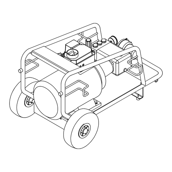
Page 37: Summary
General Technical Description Summary Below you will find an overview of the most important components; these will then be described on the following pages. Item Designation High-pressure gun with fan jet nozzle Control cabinet Unloader Pressure gauge Water filter Rating plate High-pressure water pump Engine High-pressure hose... -
Page 38: Technical Data
General Technical Description Technical data The technical data and features listed below relate to the Dynajet 350 me. Dynajet 350 me Dimensions Length: 1100 mm Width: 670 mm Height: 650 mm Weights Weight: 147 kg Performance data Electric motor Power unit:... -
Page 39: Rating Plate
General Technical Description 3.6 Rating plate The most important machine data is shown on the rating plate. Item Designation Model (machine model) Mach. no. (machine number) Year of manufacture Max. delivery pressure [bar] Voltage [V] Frequency [Hz] Power [kW] 3 — 5 02_0274_0608GB... -
Page 40: Options
The high-pressure cleaner is designed for operation with hot water that reaches a max. temperature of 95 _C. A heating module (not in- cluded in the scope of supply) must be integrated in the circuit. Item Designation Dynajet me High-pressure connecting hose Heating module High-pressure hose High-pressure gun... - Page 41 General Technical Description Note Read the documentation accompanying the heating module. You can obtain further information on options and accessories from the catalogue (Item No. MM 2599/YY) from Putzmeister Mörtelmaschinen GmbH. 3 — 7 02_0022_0608GB...
-
Page 42: Control Cabinet
General Technical Description Control cabinet The machine is controlled and operated via the control cabinet. High voltage Work on the electrical system and equipment on the machine must be carried out by a qualified electrician or by instructed persons under the supervision and guidance of a qualified electrician and in accord- ance with electrical engineering rules and regulations. -
Page 43: Drive Motor
General Technical Description Drive motor The drive motor powers the high-pressure water pump. Item Designation Drive motor Elastic coupling High-pressure water pump The drive motor has different connection values, depending on the model. Please refer to the rating plate or the machine card for the connection values of your machine. -
Page 44: Water System
General Technical Description 3.10 Water system The high-pressure water pump supplies pressurised water at a maxi- mum of 350 bar: Item Designation Pressure limiting valve with drain hose Pressure gauge High-pressure water pump Unloader High-pressure hose connection Bypass hose Water filter Low-pressure hose connection The machine is supplied with water via the low-pressure hose. -
Page 45: High-Pressure Gun With Fan Jet Nozzle
General Technical Description 3.11 High-pressure gun with The high-pressure gun meters the high-pressure water jet and is fan jet nozzle connected to the high-pressure hose. Item Designation High-pressure hose High-pressure gun trigger with safety lock High-pressure gun High-pressure pipe with insulation Fan jet nozzle Refer to the chapter: ”General Technical Description”... -
Page 46: Trigger Safety Device
General Technical Description Trigger safety device There is a trigger safety device on the high-pressure gun trigger that prevents the high-pressure gun from triggering accidentally. This red securing lever is folded in and locked and prevents personnel from actuating the gun trigger by mistake. Control line Before working with the high-pressure gun, connect this nozzle to the machine via the control line. - Page 47 General Technical Description Note Bear in mind that the nozzles have an influence on the water pres- sure. Incorrect water pressure may accelerate wear on the high- pressure cleaner. If the nozzle used is too small, the pressure may increase, which could trigger the pressure limiting valve and / or unloader and limit the system pressure.
-
Page 49: Transport, Set-Up And Connection
Transport, Set-up and Connection 4 Transport, Set-up and Connection In this section you will find information concerning safe transport of the machine. Furthermore, work is described in this section, which is also necessary for the installation and connection of the machine. Starting up the machine will not be described until the chapter ”Star- ting up”. - Page 50 Transport, Set-up and Connection 4.2 Transporting the The machine does not have any attachment points and should there- fore loaded onto a suitable transport aid (euro pallet). Use a suitable machine crane with lifting gear or a fork-lift truck to lift the machine. Danger of crushing Lift the machine carefully with a fork-lift truck and move with great care.
-
Page 51: Selecting The Set-Up Site
Transport, Set-up and Connection 4.3 Selecting the set-up The set-up site of the machine is usually determined and appropria- tely prepared by the site management. site Notes The responsibility for setting up the machine safely falls on the ope- rator. 4.4 Set-up site require- Inspect the proposed site carefully and reject the set-up site if you have any doubts in respect of safety. -
Page 52: Water Connections
Transport, Set-up and Connection 4.5 Water connections The following section describes how to connect the high-pressure cleaner to the water supply. Item Designation Connecting to the mains water supply Connection for the high-pressure hose The water supply may only be connected as per DIN 1988 - - Techni- cal Rules for Water Installations, i.e. - Page 53 Transport, Set-up and Connection Caution The water used must be clean and of drinking water quality. The maximum water temperature is 60 Never use: salt water, sea water, completely desalted water or water with added chemicals. Only add chemicals or cleaning agents on consultation with Putzmeister Mörtelmaschinen GmbH.
- Page 54 Transport, Set-up and Connection Item Designation High-pressure hose Threaded coupling High-pressure gun High-pressure pipe with insulation Fan jet nozzle " Attach the high-pressure pipe with insulation(4) and fan jet nozzle(5) to the high-pressure gun(3). " Connect the high-pressure gun(3) and the high-pressure hose(1) to the threaded coupling(2).
-
Page 55: Electrical Connection
The following versions are available: External Material no. Model Type Fuse device plug 5- -pin, 400 V, 111488003 Dynajet 350 me 400V/50Hz 35 A 32 A, 6 h red 5- -pin, 400 V, 111488029 Dynajet 350 me 400 V / 60 Hz 35 A... -
Page 56: Prerequisites
Transport, Set-up and Connection Prerequisites Electrical installation prerequisites should be checked by a qualified electrician before connection work begins. Refer to the Directives stipulated in BGI 608. - - The connected load of the existing electrical installation must be sufficient for the machine. - - Connection may only be carried out at a specific feed point (e.g. -
Page 57: Laying Electrical Supply Cables
Transport, Set-up and Connection Laying electrical supply Supply cables must be laid visibly, taking local conditions into con- cables sideration, and secured against damage. Danger There is a danger of electric shock which may have lethal conse- quences by: – contact with electrical cables; –... -
Page 59: Starting Up
Starting up 5 Starting up In this chapter you will find information on starting up the machine. The work steps for initial operation of the machine are described as well as how to prepare the machine for operation after a long break. There is also a description on how to check the condition of your ma- chine and how to carry out a test run with function checks. -
Page 60: Working Position Of The Machine
Starting up 5.1 Working position of the machine Caution The machine should only be operated in a horizontal position. A tilt switch monitors the position of the machine and makes sure that the machine can only be operated in a horizontal position. 5 —... -
Page 61: Checks
Starting up Checks Each time the machine is used at a construction site, you should check the condition of your machine and carry out a test run including function checks. If you identify any faults during the checks, you must eliminate these (or have these eliminated) immediately. -
Page 62: Water Filter
Starting up Water filter A contaminated water filter may result in damage to the high-pres- sure water pump. The filter system cleans the supplied water, thus safeguarding the high-pressure water pump. Caution Use only clean mains water. If the water filter is contaminated, the integral water deficiency moni- tor switches the machine off or prevents the machine from being started. -
Page 63: Test Run
Starting up Test run Carry out a test run before operating the machine. Switch-on conditions The following switch-on conditions must be met before the motor is started: - - The machine should be in a horizontal position (tilt switch). - - The machine must be connected to a suitable water supply (at least 2 bar pressure). -
Page 64: Automatic Star-Delta Switch
Starting up Item Designation Star-delta switch Main switch If your machine is fitted with an automatic star-delta switch, the Automatic star-delta switch machine can only be switched on via the main switch. " Switch on the main switch (2). ⇒ The engine starts up. Star-delta switch If your machine is fitted with a star-delta switch, proceed as de- scribed below:... -
Page 65: Operation
Operation 6 Operation In this section you will find information on machine operation. You will learn what operations are required for setting up the machine, operation and for cleaning. 6.1 Requirements Before starting work, you must carefully carry out the working steps for commissioning and installing the machine. -
Page 66: Setting Values
Operation 6.2 Setting values The setting values depend on the tasks being carried out. Notes There are specific setting values for every type of cleaning task to help achieve the best cleaning results. Contact Putzmeister Mörtelmaschinen GmbH for advice on the correct setting values for your specific cleaning needs. -
Page 67: High-Pressure Cleaning
Operation High-pressure cleaning For cleaning work, proceed as follows: Danger Wear all necessary protective equipment. This also applies for all personnel standing within the operating area of the machine (for their own safety). Never direct the water jet at people or animals. Pay attention to the confines of the danger area when performing work involving high-pressure water jets. -
Page 68: Automatic Star-Delta Switch
Operation Item Designation Star-delta switch Main switch If your machine is fitted with an automatic star-delta switch, the Automatic star-delta switch machine can only be switched on via the main switch. " Switch on the main switch (2). ⇒ The engine starts up. Star-delta switch If your machine is fitted with a star-delta switch, proceed as de- scribed below:... -
Page 69: Adjusting The Working Pressure
Operation Adjusting the working You can adjust the working pressure by turning the unloader. pressure Note There is no motor speed adjustment feature on the engine. The en- gine speed is controlled depending on the load. Item Designation Handwheel on the unloader "... - Page 70 Operation 6.5 Operating the heating The high-pressure cleaner is designed for operation with hot water that reaches a max. temperature of 95 °C. A heating module (not inc- module (optional) luded in the scope of supply) must be integrated in the system. Read the ”Heating module”...
-
Page 71: Cleaning The Machine
Operation Cleaning the machine After completing your work, clean the machine, the high-pressure gun and the high-pressure hose. This ensures that the machine will function correctly the next time it is used. Information on cleaning Prior to cleaning the machine, cover or seal all openings where moisture should not enter for safety or operating reasons. - Page 72 Operation Caution Do not clean the control cabinet or the engine with pressurised water. Cover all openings prior to cleaning. For safety or operating reasons, moisture must not be allowed to enter these openings. Environmental protection Observe all applicable local waste disposal regulations when per- forming cleaning work.
-
Page 73: Water Filter
Operation Water filter The amount of dirt on the water filter depends on the water quality. The filter element changes colour when dirty. Clean or replace the filter element if it changes in colour or the maintenance intervals have been reached. Read the ”Maintenance intervals” section in the chapter ”Maintenance”. -
Page 75: Faults, Cause And Remedy
Faults, Cause and Remedy 7 Faults, Cause and Remedy This section gives you a summary of faults and their possible cau- ses, and also ways in which you may rectify them. Observe the safety regulations when troubleshooting. Heavy current Work on the electrical system and equipment of the machine must be carried out by a qualified electrician or by instructed personnel under the supervision and guidance of a qualified electrician and in accordance with electrical engineering rules and regulations. -
Page 76: Machine, General
Faults, Cause and Remedy 7.1 Machine, general The following section provides a description of possible causes of faults and their remedies. The operating pressure fluctuates Cause Remedy The water filter is contami- Clean or replace the water filter. nated. The fan jet nozzle is blocked or Clean or replace the fan jet nozzle. -
Page 77: Electrical System
Faults, Cause and Remedy 7.2 Electrical system The following is a description of possible causes of faults, which af- fect the electrical system, and their remedies. Heavy current Work on the electrical system and equipment of the machine must be carried out by a qualified electrician or by instructed persons un- der the supervision and guidance of a qualified electrician and in accordance with the electrical engineering rules and regulations. - Page 78 Faults, Cause and Remedy The fuse has triggered Cause Remedy The fuse on the machine is too Use the correct fuse. small. The fuse triggers too readily. Use the correct fuse. The diameter of the electric Use a supply lead with a larger diameter. supply lead is too narrow.
- Page 79 Maintenance 8 Maintenance In this section you will find information on the maintenance work ne- cessary for the safe and efficient operation of the machine. We would like to emphasise here that all specified checks, inspec- tions and preventive maintenance work must be conscientiously car- ried out.
-
Page 80: Maintenance Intervals
Maintenance Maintenance intervals The following table shows the intervals for the various maintenance tasks. Note Have the initial after-sales service carried out by a Putzmeister Mörtelmaschinen GmbH After Sales service engineer or by a dealer authorised by Putzmeister Mörtelmaschinen GmbH. Inspection Interval Assembly... -
Page 81: General Tightening Torques
Maintenance Inspection Interval Assembly Measure Reference criterion 500 h High-pressure Full oil change Change oil after the Chapter ”Mainten- water pump first oil change ance” - - section: Op- erating materials” annually Entire machine Industrial safety Industrial safety in- Use industrial safety inspection spection by qualified inspection form... -
Page 82: Operating Materials
Maintenance 8.2 Operating materials This section lists all the operating materials used in your machine. High-pressure water The high-pressure water pump is filled with 0.9 kg SAE 30 W ex- pump works. Environmental protection You must carefully collect all operating materials, e.g. used oil, filters and auxiliary materials and dispose of them separately from other waste. -
Page 83: Temporary Decommissioning
Decommissioning 9 Decommissioning This chapter contains information on decommissioning the machine. Temporary decommis- If the machine is to be shut down temporarily, take the following sioning measures. " Switch off the machine. " Cut off the water supply. " Actuate the high-pressure gun until water no longer escapes and the machine is depressurised. - Page 84 Decommissioning Item Designation Water filter " Unscrew the union nut on the water filter (1) and remove the filter casing and filter element. " Position the machine so that the any residual water can drain from the water pipeline and high-pressure pump. "...
-
Page 85: Decommissioning
Decommissioning 9.2 Decommissioning If the machine is to be taken out of service temporarily, the following measures must be carried out. " Carry out the tasks for temporary decommissioning. " Before storing the machine, top it up with all the service fluids and grease it at the lubrication points. -
Page 86: Final Decommissioning, Disposal
Decommissioning 9.3 Final decommissio- The final decommissioning and disposal requires complete disas- sembly of the machine into its individual components. ning, disposal When disposing of all machine components, ensure that there is no possibility of damage to health or the environment. Environmental protection Final disposal of the machine is carried out by a qualified specialist company. -
Page 87: Material Used
Decommissioning Material used The main materials used for machine construction were: Material Use for / in Copper - - Cables - - Machine frame Steel Steel - - Pump units - - Gaskets - - Hoses Plastic, rubber, PVC Plastic, rubber, PVC - - Cables - - Wheels - - PCBs... - Page 89 Appendix 10 Appendix 10.1 General tightening Tightening torques depend on bolt grade, thread friction and bolt head bearing area. The values given in the following tables are for torques guidance. These values should only be used if no other values are specified in the relevant chapters of the Operating Instructions or in spare parts sheets.
- Page 90 Appendix The tables below give the maximum tightening torques (maximum torque) in Nm for a friction factor of mtotal = 0.14, with the thread lightly-oiled or lightly-greased. Notes All tightening torques X 1.1 apply for bolts with cement in the thread. Set screws - - metric triangular thread, DIN 13, Part 13 Dimensions Tightening torque...
- Page 91 Index of Key Words Index of Key Words This chapter contains the main key words with the number of the page on which they are to be found as a header in the left-hand margin. This Index of key words is listed alphabetically by the main concepts.
- Page 92 Index of Key Words Heating module, 3 — 6 Performance, 3 — 4 Safety devices, 2 — 5 High- -pressure cleaning, 6 — 3 Personnel, 2 — 7 Safety equipment, 2 — 9 High- -pressure gun, 3 — 11, 4 — 6 Personnel selection and qualifica- Safety regulations, Heating module, tions, 2 —...
- Page 93 Index of Key Words Visual checks, 5 — 3 Voltage, 3 — 5 Water connection, 4 — 4 - High- -pressure hose, 4 — 4 - Mains water supply, 4 — 4 Water filter, 3 — 10, 5 — 4 - Cleaning, 6 —...
- Page 94 Index of Key Words...
- Page 95 Putzmeister Limited Putzmeister France Putzmeister Chesterfield Trading Estate Zone Industrielle Mörtelmaschinen GmbH Carrwood Road Rue Jean Jaurès Max- -Eyth- -Straße 10 Sheepbridge/Chesterfield/ 91861 Epinay sous Sénart 72631 Aichtal Derbyshire S41 9QB Tel. (1) 69 39 69 39 Postfach 21 52 Tel.
- Page 96 Putzmeister Mörtelmaschinen GmbH Postfach 2152 D- -72629 Aichtal Telefon (07127) 599- -0 Telefax (07127) 599- -743 Internet: http://www.moertelmaschinen.de E- -mail: pmm@pmw.de...
Need help?
Do you have a question about the 350 me and is the answer not in the manual?
Questions and answers