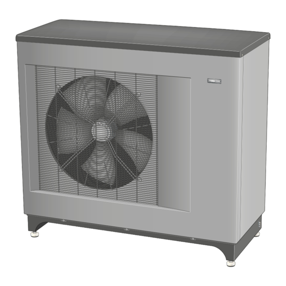
Nibe F2300 Service Manual
Air/water heat pump
Hide thumbs
Also See for F2300:
- Installer manual (56 pages) ,
- User manual (32 pages) ,
- Installer manual (52 pages)
Table of Contents
Advertisement
Quick Links
Advertisement
Table of Contents
Troubleshooting

Subscribe to Our Youtube Channel
Related Manuals for Nibe F2300


Summary of Contents for Nibe F2300
-
Page 1: Service Manual
Service manual NIBE™ F2300 Air/water heat pump SEM GB 1335-1 M11450... -
Page 3: Table Of Contents
High supply temperature High return temperature 8 Technical data MP alarm (07) Electrical circuit diagram Main contactor (QA51) Dimensions and setting-out coordinates Motor circuit breaker (FC2) Technical specifications Phase monitor (BA1) Item register Time conditions compressor NIBE™ F2300 Table of Contents |... -
Page 4: Important Information
Document information F2300 is CE marked and fulfils IP24. This technical manual is a complement to the Installer The CE marking means that NIBE ensures that the handbook for F2300, containing: product meets all regulations that are placed on it Description of functions and component description. -
Page 5: Contact Information
Puh: 09-274 697 0 Fax: 09-274 697 40 E-mail: info@nibe.fi www.nibe.fi AIT France, 10 rue des Moines, 67000 Haguenau Tel : 03 88 06 24 10 Fax : 03 88 06 90 15 E-mail: info@nibe.fr www.nibe.fr NIBE Energy Systems Ltd, 3C Broom Business Park, Bridge Way, Chesterfield S41 9QG Tel: 0845 095 1200 Fax: 0845 095 1201 E-mail: info@nibe.co.uk www.nibe.co.uk... -
Page 6: The Heat Pump Design
2 The heat pump design General Chapter 2 | The heat pump design NIBE™ F2300... - Page 7 Pipe connections Connection, heating medium out of F2300, G1 1/4" (Ø35 mm) Connection, heating medium in to F2300, G1 1/4" (Ø35 mm) XL20 Service connection, high pressure XL21 Service connection, low pressure XL40 Connection, drip tray drain (Ø40 mm) Sensors etc.
- Page 8 Terminal block, external supply Terminal block, charge pump, external heater Terminal block, common alarm Terminal block, thermostat, compressor blocking Terminal block Designations in component locations according to standard IEC 81346-1 and 81346-2. Chapter 2 | The heat pump design NIBE™ F2300...
-
Page 9: System Description
Temperature sensor, fluid pipe QN30 Solenoid valve fluid injection BT16 Temperature sensor, evaporator in QN31 Solenoid valve subcooling BT17 Temperature sensor, suction gas QN34 Expansion valve, subcooler BT28 Temperature sensor, ambient Non-return valve Evaporator NIBE™ F2300 Chapter 3 | System description... -
Page 10: Sensor Internal
On the suction pipe before View. the compressor. BT28 Surrounding area On the side panel next to the Stops comp at high and low outdoor temperature. upper part of the evaporator Switches fan speed. bend. Permits/blocks defrosting. Chapter 3 | System description NIBE™ F2300... -
Page 11: System Diagram
System diagram F2300 docked to the electric/oil-fired/pellet boiler together with SMO 05 and water heater (floating condens- ing) -AA25 -FL2 -KA10 -CM1 -AA25 -EB1 -BT25 -QM31 -GP10 -CP11 -QN26 -AA25 -AA25-AA4 -QM32 -AA25 -AA25-BT1 -AA25-BT50 -BT7 -CP10 -FL11 -QN10 -EB101... -
Page 12: Compressor Protection
(FC2), high pressure switch (BP10) or phase monitor *BA1) have tripped. Main contactor (QA51) If any of the following conditions are met, the main contactor breaks (QA51). High pressure switch (BP10) has tripped Chapter 4 | Compressor protection NIBE™ F2300... -
Page 13: Component Description
Bridge Compressor size J9:5-6 and J9:7-8 14 kW J9:3-4, J9:5-6, J9:7-8 20 kW NIBE™ F2300 Chapter 5 | Component description... -
Page 14: Sensors
1.916 5.37 2.67 5.306 1.752 4.69 2.50 4.348 1.587 4.10 2.33 3.583 1.426 2.968 1.278 2.467 1.136 2.068 1.007 1.739 0.891 1.469 0.785 1.246 0.691 1.061 0.607 0.908 0.533 0.779 0.469 0.672 0.414 Chapter 5 | Component description NIBE™ F2300... - Page 15 1.80 2.186 1.59 1.817 1.39 1.518 1.22 1.274 1.07 1.075 0.93 0.911 0.81 0.775 0.71 0.662 0.62 0.568 0.54 0.490 0.47 0.4233 0.41 0.367 0.36 0.320 0.32 0.280 0.28 0.245 0.25 0.216 0.22 NIBE™ F2300 Chapter 5 | Component description...
-
Page 16: Reference Designation
Temperature sensor, suction gas ”EMMY cold sensor” BT28 (T Temperature sensor, ambient ”EMMY cold sensor” outdoor Compressor protection Goes via fuse that breaks all three phases and via phase monitor and the fan's internal motor protection. Chapter 5 | Component description NIBE™ F2300... -
Page 17: Troubleshooting
120 stat. Check the start temperature hot water in seconds during all three of the latest compressor any NIBE Indoor module. Check the charge flow operations. and the particle filter which may be partially clogged. - Page 18 Hot gas The hot gas temperature (BT14 ) Compressor blocked. Restarts automatically when BT14 stop is greater than 135 °C. is less than 60 °C. Repeated hot gas stop can give constant hot gas alarm. Chapter 6 | Troubleshooting NIBE™ F2300...
-
Page 19: Troubleshooting Guide
Troubleshooting guide Alarm 05 – low pressure alarm NIBE™ F2300 Chapter 6 | Troubleshooting... - Page 20 - Check the heating medium Is the heating medium flow pump. correct? - Open any radiator thermostats. - Check the particle filter. Fault in cooling circuit. Contact an authorised refrigeration technician. Chapter 6 | Troubleshooting NIBE™ F2300...
- Page 21 Alarm 08 – sensor fault Check which sensor is giving an alarm, the value appears as ”--” in the display. Alarm 09 - communication alarm Alarm 12 - Incorrectly installed sensor NIBE™ F2300 Chapter 6 | Troubleshooting...
- Page 22 Alarm 15 - Defrosting alarm Alarm 16 - short operating times Chapter 6 | Troubleshooting NIBE™ F2300...
- Page 23 Alarm 17 - hot gas alarm NIBE™ F2300 Chapter 6 | Troubleshooting...
-
Page 24: Function Check, Relays/Components
4-way valve (QN02). Solenoid valve fluid injec- tion (QN30). Solenoid valve subcooling (QN31). Compressor heater (EB10). Heater condensation (EB11). Collar heater (EB13). Compressor (GQ10). Charge pump (Sometimes referred to as circ. Pump) (GP12). Alarm relay Chapter 6 | Troubleshooting NIBE™ F2300... -
Page 25: Component Replacement
NOTE The door is opened using a Torx 25 screw- driver. Removing electrical cabinet Unscrew the screws and lift off the cover. Dismantling motor module Unscrew the screws and lift off the cover. NIBE™ F2300 Chapter 7 | Component replacement... -
Page 26: Main Components
2 Remove the front panel's four screws and then the two screws for the side pan- 3 Remove the compressor insulation and the terminal protection at the connection. 4 Disconnect the connection cables. Chapter 7 | Component replacement NIBE™ F2300... - Page 27 7 Disconnect the pipes for suction gas and hot gas. 8 Pull off the clips on the bolts to the compressor. 9 Lift the compressor out. 10 Reassemble in reverse or- der. NIBE™ F2300 Chapter 7 | Component replacement...
- Page 28 3 Cut off the cable tie for the wiring and pipe to the evap- orator. 4 Then pull the panel out until the expansion valve is accessible. Chapter 7 | Component replacement NIBE™ F2300...
- Page 29 6 Remove the pipe insulation covering the bulb and expan- sion valve. 7 Slacken off the bulb for the expansion valve. 8 Remove the pipe and re- move the valve. 9 Reassemble in reverse or- der. NIBE™ F2300 Chapter 7 | Component replacement...
- Page 30 2 Remove the front panel's four screws and then the three screws for the side panel. 3 Disconnect the fan cable's electrical connector. 4 Remove the fan grille by slackening off the four screws. Chapter 7 | Component replacement NIBE™ F2300...
- Page 31 5 Remove the screws and then the fan motor. 6 Reassemble in reverse or- der. Condensation water trough (WM5) 1 Remove the condensation pipe. 2. Fold the two black handles down. 3 Remove the trough. NIBE™ F2300 Chapter 7 | Component replacement...
-
Page 32: Circuit Board And Electronics
3 Remove the edge board connectors and then the four supports. 4. Remove the control card. 5. Transfer the edge board connectors to the new card. Chapter 7 | Component replacement NIBE™ F2300... -
Page 33: Technical Data
8 Technical data Electrical circuit diagram NIBE™ F2300 Chapter 8 | Technical data... - Page 34 Chapter 8 | Technical data NIBE™ F2300...
- Page 35 NIBE™ F2300 Chapter 8 | Technical data...
- Page 36 Chapter 8 | Technical data NIBE™ F2300...
-
Page 37: Dimensions And Setting-Out Coordinates
Dimensions and setting-out coordinates 1345 Ø 1455 Fritt utrymme bakom 600 mm Min. avstånd vid användning av flera F2300 Fritt utrymme framför NIBE™ F2300 Chapter 8 | Technical data... -
Page 38: Technical Specifications
Defrosting system hot gas defrosting Heating medium Min/Max system pressure heating medium 0.05/0.3 (0.5/3 bar) Nominal flow (Min flow during defrosting.) 0.33/0.67 0.47/0.94 Min/Max flow 0.33 0.47 Internal pressure drop at nominal flow Chapter 8 | Technical data NIBE™ F2300... - Page 39 If the impedance in the mains connection point is higher than that stated check with the power supplier before purchasing the equipment. Nominal flow corresponding DT=10 K at 7/45. NIBE™ F2300 Chapter 8 | Technical data...
- Page 40 Working area Water temperature °C Supply temperature Return temp Outdoor air temperature °C During shorter time it is allowed to have lower working temperatures on the water side, e.g. during start up. Chapter 8 | Technical data NIBE™ F2300...
-
Page 41: Item Register
B alarm - Automatic resettable alarm, 16 High return temperature, 10 Function check, relays/components, 22 High supply temperature, 10 Troubleshooting guide, 17 Hot gas temperature, 10 Troubleshooting guide, 17 Important information, 2 Working area, 10 Document information, 2 NIBE™ F2300 Chapter 9 | Item register... - Page 43 NIBE AB Sweden Hannabadsvägen 5 Box 14 SE-285 21 Markaryd info@nibe.se www.nibe.eu...
Need help?
Do you have a question about the F2300 and is the answer not in the manual?
Questions and answers