
Subscribe to Our Youtube Channel
Related Manuals for Toolex 535819


Summary of Contents for Toolex 535819
-
Page 1: Instruction Manual
535819 TILTING ARBOR TABLE SAW Tilting Arbor Table Saw INSTRUCTION MANUAL CONSUMER SERVICE CENTRE PO BOX 1012 HAMILTON NSW 2303 AUSTRALIA Made in P.R.C. -
Page 2: Table Of Contents
TABLE OF CONTENTS PREFACE .......................... 0 GENERAL SAFETY RULES FOR WOODWORKING MACHINERY ......0 ADDITIONAL SAFETY RULES FOR CIRCULAR SAWS ..........0 ASSEMBLY INSTRUCTION ................... 0 SPECIFICATIONS ......................1 ELECTRICAL........................1 WIRING DIAGRAMS ....................... 1 ... -
Page 3: Preface
PREFACE Thank you for choosing this tilting arbor table saw. We are pleased to offer you our best machinery and service, and trust that you will find our machinery economical, productive and easy to operate. This manual covers the proper operation, safety and maintenance of the machine. It is important that this manual be read in its entirety before operating the machine. - Page 4 11. WEAR PROPER APPAREL. No loose clothing, gloves, neckties, rings, bracelets, or jewelry to get caught in moving parts. Non-slip footwear is recommended. Wear protective hair covering to contain long hair. 12. ALWAYS USE SAFETY GLASSES. Also use face or dust mask if cutting operation is dusty. Everyday eyeglasses only have impact resistant lenses, they are NOT safety glasses.
-
Page 5: Additional Safety Rules For Circular Saws
ADDITIONAL SAFETY RULES FOR CIRCULAR SAWS ALWAYS use saw-blade guard and spreader for every operation for which it can be used, including all through sawing. Thru-sawing operations those when the blade cuts completely through the work piece as in ripping or cross cutting. ALWAYS hold the work firmly against the miter gage or fence. -
Page 6: Specifications
Straightedge. Socket Wrench (recommended) and Large slot and large Phillips screwdrivers. Adjustable wrench. SPECIFICATIONS MODEL 10LP-A Speed 4000R.P.M Diameter of arbor 5/8”(16mm) Diameter of cut 10”(254mm) MAX. depth of cut 3-1/8”(79mm) MAX. depth of cut at 45. 2-1/8”(54mm) Distance in front of blade 10.23”(260mm) Table (LXM) 686X512mm... -
Page 7: Electrical
operation when plugged into an outlet, double check the power supply. ELECTRICAL SPEED AND WIRING The no-load speed of your table saw is EXTENSION CORDS approximately 3600 rpm. This speed is not Use only 3-wire extension cords that have 3-prong constant and decreases under a load or with lower grounding plugs and 3-pole receptacles that accept voltage. - Page 8 ※ Note: In Canada, the use of a temporary adaptor is not permitted by the Canadian Electrical Code. 3. Grounded, cord-connected tools intended for use on a supply circuit having a nominal rating between 150-250V, inclusive: This tool is intended for use on a circuit that has an outlet that looks like the one illustrated in Sketch D in Figure 1.2.
-
Page 9: Wiring Diagrams
WIRING DIAGRAMS When rewiring the supplied electric motor, be sure power cord is unplugged then change the connection as illustrated below. Always secure wire nuts with friction tap. A new plug will be required. NOTE: The reconnection shall be made by qualified electrician or service personnel. 1. -
Page 10: Glossary Of Terms For Woodworking
Fig1.4 GLOSSARY OF TERMS FOR WOODWORKING The end of the workpiece pushed into the cutting tool Anti-Kickback Pawls first. Toothed safety devices behind the blade designed Miter Cut to stop a workpiece from being kicked back at the operator during a ripping operation. A cutting operation made with the miter gage at any angle other than 0°... -
Page 11: Machine Legend
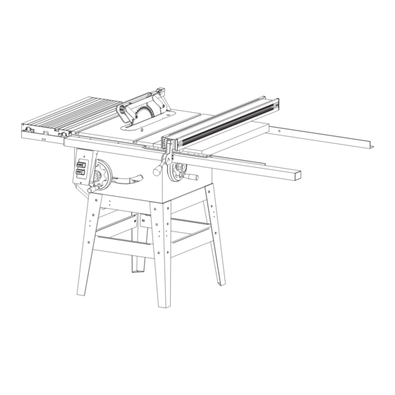
Workpiece Worktable The item on which the cutting operation is being The surface on which the workpiece rests while done. The surfaces of a workpiece are commonly performing a cutting operation. referred to as faces, ends, and edges. MACHINE LEGEND Blade cover Ant i-kickback pawls Handle... - Page 12 OVERVIEW The upper position of the blade projects up through the table, surrounded by an insert called the thru plate. The height of the blade is set with a hand wheel on the front of the cabinet. To accommodate wide panels, the tabletop has extensions on each side. Detailed instructions are provided in the Operation section of this manual for the basic cuts:Cross cuts, miter cuts, bevel cuts, and compound cuts.
- Page 13 Grooves run along the top and sides of the rip fence for use with optional clamps and accessories. RIP FENCE HANDLE – The handle on the front of the rip fence releases the rip fence or locks it in place. RIVING KNIFE OR SPREADER –...
-
Page 14: Assemble And Adjustments
ASSEMBLE AND ADJUSTMENTS ASSEMBLE THE RAISING AND TILTING HANDWHEELS AND LOCK KNOBS Place the wheels in position over the raising and tilting screws being sure to engage the slots, a (Fig.3), in back of each wheel with the roll pins, b(Fig.3), as shown at right. Screw on lock knobs c(Fig.4), to hold wheels in place, then attach silver handles, d(Fig.4) tightening them with the supplied 12mm combination wrench. - Page 15 Be sure that extension wings are flush with front edge of table and that the painted ends face out.
- Page 16 ASSEMBLE AND ADJUSTMENTS CHECK HEELING (PARALLELING) MARKED TOOTH OF THE SAWBLADE TO THE MARKED TOOTH MITER GAGE GROOVE AT FRONT MITER GAGE GROOVE See Figures 7 and 8. DO NOT loosen any screws until you have checked with a square and made sure adjustments are necessary.
-
Page 17: Assemble And Adjustments
ASSEMBLE AND ADJUSTMENTS CHECKING SQUARENESS OF EXTENSION TABLES SAW TABLE See Figure 9 and 10. The extension wing should be checked for squatness to the saw table for smooth operation of the rip fence and rails. Place a square on the saw table, with the short end up and check .The long end of the square should extend across one of the extension wing. -
Page 18: Assemble And Adjustments
ASSEMBLE AND ADJUSTMENTS CHANGING THE SAW BLADE. Attention: left hand thread. Remove the arbor nut (J) and flange (I). Place saw blade on arbor shaft making sure teeth point down at the front of the saw. Reinstall flange and arbor nut and securely tighten. Remove the locking pin (K). - Page 19 The handle(L) should keep up as Fig.13. When install the riving knife. Then fix the handle(L) by rotation after riving knife installation as Fig.14. Fig. 13 Fig. 14 TO ADJUST THE RIVING KNIFE: 1. Disconnect the saw from the power source. 2.
- Page 20 6. Use the set screws shown in Figure 17 to adjust the riving knife bracket and re-install the riving knife. Fig.17 (set screw for adjusting riving knife) 7. Repeat step 3-7 until the riving knife is centered on the blade and aligned at 90∘to the table. 8.
-
Page 21: Switch Installation
4. Put down the guards (N) as Fig.20 and lock the handle(M), then fix the handle(M) as Fig.21. Fig.20 Fig.21 Check the 45 setting. Tilt the blade with the bevel hand wheel as far as it will go to the left. Place the square against the blade (be sure the square is not against one of the saw teeth). -
Page 22: Adjusting The Miter Gauge
Install the switch on the location as Fig.23 with the hex. Screw 1/4”X20UNCX5/8”. Lock the screw under the Front rail, and make sure you have lock including star washer A as Fig.23. Fig.23 The table saw is equipped with a push-button switch that will accept a padlock (not included) for locking the switch in the OFF position. -
Page 23: Assembly Diagram
See Figure 25. You can set the miter gauge at 0 and plus or minus 45 with the miter gauge stop pin and adjustable stop screws. Note:The miter gauge provides close accuracy in angled cuts. For very close tolerancesm, test cuts are recommended. Loosen knob and pull out on stop pin to rotate miter gauge base past stop screws. - Page 24 10LP-A ASSEMBLY DIAGRAM...
-
Page 25: Assembly Diagram
10LP-A ASSEMBLY DIAGRAM... -
Page 26: Assembly Diagram
10LP-A ASSEMBLY DIAGRAM... - Page 27 10LP-A...
- Page 30 14-Mar-12 TSC-10LPA PARTS LIST Part. No. Description Q’ty 13300020 Table E0000002 Extension wing 12700003b Table insert 13300002P Cabinet 13200004 Motor cover 10105056a handle 10108005 Hand wheel 13200032 Wheel cover 13200013 J1330001 Angel label 13200018b Foot Stand 11107098 Rubber Feet 13200019 SIDE BRACKET 13200021 TOP SHORT BRACKET...
- Page 31 M133A005 Motor 1.5HP/ 240/50/1PH 13300012 Motor plate 13200009 Motor pulley 13200016L Lifting screw 20900028 Bush 13200014 Arbor 13200033 Clamp shoe 13200027 Sleeve 11105064 Rod cap 13300017 Angel indicator 20900022 Gear V13207190 Belt 13300010 Gear cover 20701006 Bearing 11105081 Spring 13200029 Bracket 12700057 Screw...
- Page 32 12700013 Shaft C1206202A Bearing C5151102 Bearing 13200028 Ring S0050505M Set screw M5XP0.8X5 S0021025M Hex. Screw M10XP1.5X25 S0231000M Spring washer Ø10 S0211021 Flat washer 10X21X2t C1106201 Bearing 13200031 Position ring S0020820M Hex. Screw M8XP1.25X20 S0230800M Spring washer Ø8 S0210516 Flat washer 8X16X2t C5151104 Bearing 13200040...
- Page 33 S0111400L Hex. Nut M14XP2.0 S0021020M Hex. Screw M10XP1.5X20 S0210540 Flat washer 5/8"X40X3t S0120580 Locking nut 5/8"-11UNC S0050510M Set screw M5XP0.8X10 S0120800M Locking nut M8XP1.25 S0050103 Set screw 1/4"-20UNCX3/8" S0210500b Flat washer 8X22X3t S0112000M Hex. Nut M20XP2.5 S00505605M Set screw M6XP1.0X5 S0110800M Hex.
- Page 34 S0230400 Spring washer Ø1/4" S0210401a Flat washer Ø1/4"xØ13x1t S0220400 Teeth washer 1/4" 10105090Q Wrench S0911417 Open end wrench S0911012 Open end wrench S0910206 L-wrench 6mm S0910204 L-wrench 4mm S0910203 L-wrench 3mm 13000004 Riving knife 12700005 Supporting arm 12700006 Guard (left) 12700007 Guard (right) 12700067...
- Page 35 S0120600M Locking nut S0010635M Cap screw M6XP1.0X35 12700054 Handle 12700061 Fixed plate S0310530 Pin Ø5-30 12700062 Guard S0010512M Cap screw M5XP0.8X12 12700038 Supporting plate JG133001 Warning label 10104046 Miter gauge 10104048c Guide bar 10104045 Handle 10104050 Indicator 10104049Q Position plate 10104047 S0210501 Flat washer...
- Page 38 FB3G PART LIST DESCRIPTION Q'TY MS NO. FENCE BODY 11000001a FENCE SIDEBOARD 11000008b FENCE CAP 11000021 FENCE SIDEBOARD CAP 11000022 SCREW 5/16"-18UNC 11001021k CLAMP BLOCK 11003003 HANDLE 11000004G KNOB 11000005 CLEAR INDICATOR 11000015 PLASTIC PAD (SLIDER) 19*50*2t 11000024 SOCKET SET SCREW 5/16"-18UNC*1/4" S0050504 WASHER 3/16 S0210300...
- Page 39 FRONT RAIL RACK 11000032G HEX. HEAD SCREW 1/4"-20UNC-3/4" S0020412 LONG SCALE 30" 11000018 NYLON SCREW M12*1.75-12L 11003017 WASHER 5/16" S0210500 HEX. NUT 5/16"-18UNC S0120500 TIGHTENING ROD PLATE 11001010a S0310506...
Need help?
Do you have a question about the 535819 and is the answer not in the manual?
Questions and answers