Sime RMG 100 Mk.II Installer's Instructions
Hot water generators
Hide thumbs
Also See for RMG 100 Mk.II:
- Installer's instructions (56 pages) ,
- Installation instructions manual (96 pages)
Advertisement
Quick Links
CONTENTS
1
DESCRIPTION OF THE BOILER . . . . . . . . . . . . . . . . . . . . . . . . . . . . . . . . . . . . . . . . . . . . . . . . . . . . . . . . . . . . . . . . . . . . . . . . pag. 46
2
INSTALLATION . . . . . . . . . . . . . . . . . . . . . . . . . . . . . . . . . . . . . . . . . . . . . . . . . . . . . . . . . . . . . . . . . . . . . . . . . . . . . . . . . . . . . . . pag. 47
3
CHARACTERISTICS . . . . . . . . . . . . . . . . . . . . . . . . . . . . . . . . . . . . . . . . . . . . . . . . . . . . . . . . . . . . . . . . . . . . . . . . . . . . . . . . . . . pag.
4
USE AND MAINTENANCE . . . . . . . . . . . . . . . . . . . . . . . . . . . . . . . . . . . . . . . . . . . . . . . . . . . . . . . . . . . . . . . . . . . . . . . . . . . . pag. 53
When carrying out commissioning of the boiler, you are highly recommended to perform the following checks:
- Make sure that there are no liquids or inflammable materials in the immediate vicinity of the boiler.
- Make sure that the electrical connections have been made correctly and that the earth wire is connected to a good
earthing system.
- Open the gas tap and check the soundness of the connections, including that of the burner.
- Make sure that the boiler is set for operation for the type of gas supplied.
- Check that the flue pipe for the outlet of the products of the combustion is unobstructed.
- Make sure that any shutoff valves are open.
- Make sure that the system is charged with water and is thoroughly vented.
- Purge the system, bleeding off the air present in the gas pipe by operating the pressure relief valve on the gas
valve inlet.
INSTALLER INSTRUCTIONS
IMPORTANT
51
Advertisement

Related Manuals for Sime RMG 100 Mk.II


Summary of Contents for Sime RMG 100 Mk.II
- Page 1 INSTALLER INSTRUCTIONS CONTENTS DESCRIPTION OF THE BOILER ............... . pag. 46 INSTALLATION .
-
Page 2: Description Of The Boiler
G Gas connection 1” Boiler/filling drain 3/4” ø mm RMG 70 Mk.II RMG 80 Mk.II RMG 90 Mk.II 1040 RMG 100 Mk.II 1140 Fig. 1 TECHNICAL FEATURES RMG 70 Mk.II RMG 80 Mk.II RMG 90 Mk.II RMG 100 Mk.II Heat output 49. -
Page 3: Installation
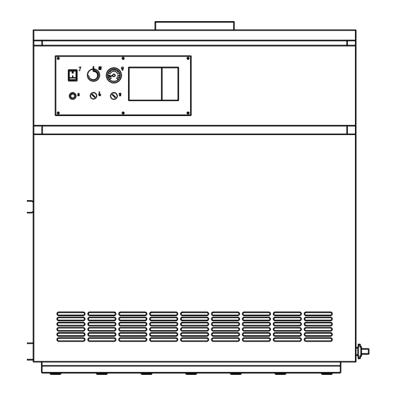
MAIN COMPONENTS 1 Gas valve with coil assembly 2 1/2” bulb holder 3 Safety stat 4 Lock out reset button 5 Main switch 6 Regulation sta with double contact 7 Thermometer 8 Smoke stat 9 1/8” pressure test point 10 Burner manifold Fig. - Page 4 2. 1 . 1 Handling Once the boiler is in its place of instal- lation and the packaging has been removed, proceed as follows if it must be moved (fig. 3/a): – remove the casing cover; – attach the lifting brackets (located on the rear of the boiler) and fasten it in place with the screws provided;...
- Page 5 Should this require replace- essential condition for efficient boiler ment, it must be purchased exclusi- operation. vely from SIME. The electric power 2.6. 1 Control system The main factors to be taken into con- supply to the boiler must be 230V-...
- Page 6 The connectors are polarised in such a way that the order cannot be inverted. To install the control system these con- nectors must be connected and 1 EMC filter jumpers 4-5 and 11-12 must be 2 Control system removed from the terminal board connectors (marked in bold in fig.
-
Page 7: Characteristics
CONTROL SYSTEM RVA43.222 (optional) 1 Plastic hole cover All the boiler functions can be operated 2 Control system by the optional control system code 8096303, supplied with external tem- °C perature sensor (SE), boiler immersion sensor (SC) (fig. 7). Another series of low tension connectors may be con- nected to the control system, these are used for the connection of the sen-... - Page 8 3. 1 . 1 Operating cycle sensing electrode or the electrode of the coil assembly installed on the itself is earthed: the electrode is gas valve regulator. Before igniting the boiler, use a voltme- worn out and needs replacing. This step-modulation system affords ter to make sure that the electrical The control box is falty the following advantages:...
-
Page 9: Use And Maintenance
Burner max. pressure mbar 9. 1 goes out completely. Calibration of the Burner min. pressure mbar operating pressures is done by SIME in Butane - G30 the factory. Consequently they should Burner max. pressure mbar 25.2 25.4 25. - Page 10 the LPG adaptor code 6248301 onto the gas valve (5 fig. 10). To adjust the operating pressures, refer to section 4.2. When the working pressures have been adjusted, reseal the regulators. After have ultimated the conversion of the boiler, please stick onto the casing panel the plate showing the relevant feeding gas which is included into the conversion kit.
- Page 11 are not correct (make sure the – There is no differential on setting of – Poor ventilation of premises where cables are placed on terminals 6 the two contacts of the regulating boiler is installed. and 7 of the boiler terminal board). thermostat;...
Need help?
Do you have a question about the RMG 100 Mk.II and is the answer not in the manual?
Questions and answers