
Subscribe to Our Youtube Channel
Related Manuals for pro bel AXIS

Summary of Contents for pro bel AXIS
-
Page 1: Table Of Contents
AXIS USER GUIDE Contents Introduction Installation 2.1 Rear panel layouts 2.1.1 Digital/ Analogue Video and Unbalanced Digital Audio 2.1.2 Balanced Digital Audio 2.1.3 Analogue Audio 2.1.4 HD Digital Video 2.2 Ventilation 2.3 Power supplies 2.4 Signal connections 2.4.1 Analogue/ digital video, unbalanced digital audio and HD digital video 2.4.2 Digital audio (balanced) connector pinout... - Page 2 5.4 Port definitions 5.4.1 Port characteristics 5.4.2 Pro-Bel General Switcher Protocol (SW-P-02) 5.4.3 Pro-Bel General Remote Control Protocol (SW-P-08) Configuring the database 6.1 The Axis database editor 6.1.1 Hardware requirements 6.1.2 Installing the Editors 6.2 Understanding the database 6.2.1 Level types 6.2.2 Source and destination associations...
- Page 3 AXIS user guide 6.2.4 Destination association names 6.2.5 Route inhibits 6.2.6 Salvos 6.2.7 Configuring source keypads 6.2.8 Configuring destination keypad 6.2.9 Assigning panel types and keypads 6.2.10 Assigning source overrides 6.2.11 Assigning controllable destination association indices 6.2.12 Assigning controllable levels/brightness 6.2.13 Configuring port characteristics...
-
Page 4: Introduction
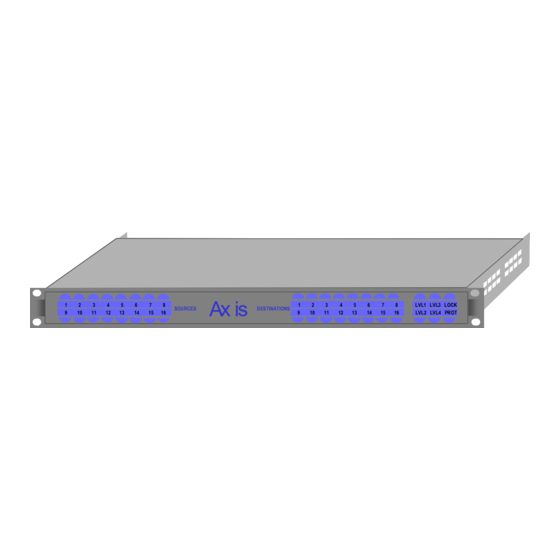
AXIS user guide Introduction The Axis router family addresses the need for smaller utility routers, by providing a range of compact, 1U, 16x16 self contained routing switchers for SDI and HD video, analogue video, balanced or unbalanced AES digital audio and stereo analogue audio signal formats. -
Page 5: Installation
The Axis range of self-contained routing switchers are supplied as fixed frame units and therefore do not contain any user serviceable parts. Should you experience any difficulties with any Axis frame, please refer first to Chapter 7 – Trouble Shooting, and then if you are still having difficulties contact customer support as detailed in Chapter 9 of this handbook. -
Page 6: Ventilation
PSU is required The mains (line) input to each Axis unit should be connected via the IEC connector fitted on the rear of the frame at the left hand side. For additional safety, the IEC connector is fitted with an integrated fuse holder. -
Page 7: Signal Connections
For EMC and safety reasons the mains, chassis and signal earths are permanently connected together within the frame. Axis slave frames, and Master frames without an integral panel, are fitted with a power present LED (V) on the front panel indicating that power is present on the router module. -
Page 8: Digital Audio (Balanced) Connector Pinout
AXIS user guide 2.4.2 Digital audio (balanced) connector pinout SLAVE BUS SLAVE BUS Outputs 1 – 16 Outputs 1 – 16 Inputs 1 – 16 Inputs 1 – 16 VID REF LEVEL VID REF LEVEL CONTROL CONTROL Output connector Input connector 50 way ‘D’... -
Page 9: Analogue Audio Connector Pinout
AXIS user guide 2.4.3 Analogue audio connector pinout SLAVE BUS SLAVE BUS Outputs 9 – 16 Outputs 9 – 16 Outputs 1 – 8 Outputs 1 – 8 Inputs 9 – 16 Inputs 9 – 16 Inputs 1 – 8 Inputs 1 –... -
Page 10: Control Connections
2.5.1 Serial control connector The control port is only active on Master Axis frames and, depending upon the database option fitted, provides either two or three serial ports. The following table details the pin out for the 15 way connector carrying these control connections. - Page 11 AXIS user guide Each Master Axis frame is supplied with a 0.5 metre breakout cable, detailed below, to facilitate easy connection to the system control ports. The cable permits Pro-Bel control panels to be connected to the unit using a pin-to-pin cable.
-
Page 12: Parallel Control Connector
AXIS user guide 2.5.2 Parallel control connector The Parallel control connector provided on both Master and Slave frames, labelled as ‘SLAVE BUS’, extends the internal crosspoint control bus to the rear of each frame. This permits slave frames to be interconnected using the three way control cable (shown below) supplied with them to construct multi-level routing switchers. -
Page 13: Led Indicators
– only that frame will respond. Video reference While every Axis frame is supplied with a terminating video reference input, it is only necessary to provide a reference signal, ideally colour black or any stable analogue video signal, to the Master frame within the system. -
Page 14: Aes Reference
AES signal present at all times. Setting the level switches Each Axis frame, whether it is a Master or Slave variant, must have its address set from the rear panel. In order to provide a system offering multilevel breakaway, each frame must have a unique address. -
Page 15: Hardware Configuration
This controller can be used either as a system controller, providing control for a standalone Axis routing system with up to eight breakaway levels, or to accept control from an external system controller allowing the frame to operate as a standalone router. -
Page 16: Slave Frames
Slave frames are fitted with a parallel control port enabling them to be connected to a Master frame as part of a multilevel routing system. Because Axis frames utilise the same control pin out as the Freeway control bus, they can also be connected to Freeway systems and controlled as additional router levels. -
Page 17: System Interconnections
Where an Axis frame is supplied with a front mounted control panel, it forms an integral part of the Axis housing and therefore should not be removed from the frame. -
Page 18: Other Control Options
Pro-Bel general switcher protocol on the remote control port, ensures seamless operation of Axis frames with all Pro-Bel control systems. Axis Slave frames may be used within Freeway routing systems, providing additional, smaller router levels working alongside base router frames. -
Page 19: Fixed Database Systems
AXIS user guide Fixed database systems Systems supplied with a fixed database contain a single, non-editable, database. In these systems, the editor port – port 3 is disabled and does not therefore permit any system changes to be made. This section details the database settings and control panels that can be used. -
Page 20: Panel Details
6700 series control panel user guide, however it is important to ensure that the panel is configured for both the correct control system and panel operation. The following table details the switch settings required for each panel type to provide correct operation with an Axis system. Switch settings Panel type... -
Page 21: Remote Control Options
Remote control options Because Axis level types are entered into the database as Freeway 64 level types, the destination offset for the next level when controlling the system remotely (using Pro-Bel general switcher protocol - SW-P-02) is 64 and NOT 16. -
Page 22: Pro-Bel General Switcher Protocol (Sw-P-02)
AXIS user guide Port Name Standard Protocol Baud Data Parity Stop rate bits bits Device port (port 1) RS485 SW-P-06 38400 Remote control (port 2) RS485 SW-P-02 38400 4.4.2 Pro-Bel General Switcher Protocol (SW-P-02) Pro-Bel General Switcher Communication Protocol is a robust, asynchronous method of controlling routing switchers. -
Page 23: Editable Database Systems
AXIS user guide Editable database systems Axis systems utilise the Pro-Bel Router Editor to program the system database, and also have the ability to provide many of the advanced operations available to Freeway systems, such as audio modify for the analogue audio level. This section details pertinent points that should be noted when configuring an Axis database. -
Page 24: Panel Details
The following table details the switch settings required for each panel type to provide correct operation with an Axis system. Switch settings... -
Page 25: General Panel Details
5.2.2 General panel details An Axis router can drive up to sixteen multi-dropped panels from each of the two RS485 General Remote ports. Each panel on the same RS485 port must be set, according to its handbook, to have a unique multi-drop address. - Page 26 AXIS user guide 5.2.3.2 Line-up This is a continuous toggle of preset and program sources allowing easier alignment of sources on a matrix level. Line-up of sources is selected as follows: • Route source to be aligned to desired destination.
- Page 27 AXIS user guide assigned to the panel. This function is typically used with multi-output panels. 5.2.3.5 Dest-ident The <DEST-IDENT> button is used to identify the destination associations assigned to the <TAKE> buttons on multi-bus panels. Pressing and holding down the <DEST-IDENT>...
- Page 28 AXIS user guide 5.2.3.8 Clear This key is used as a source preset or destination clear key and is generally assigned to the bottom right key on a keypad. 5.2.3.9 Controllable destinations This applies to X-Y panels only. The user can configure any destination association to be controllable from a given X-Y type panel.
- Page 29 AXIS user guide 5.2.3.13 Display AUD parameters This is an assignable feature to the special function buttons on 6276 X-Y and 6277 multi- bus panels only. When enabled this feature displays source and destination AUD parameters in the eighth character of the displays for the most significant stereo Analogue Audio level in the system.
- Page 30 • An override is not active on this destination unless the source is a higher priority override The router is recognised as present by the Axis control card. 5.2.3.18 Special Function Keys 6276 and 6277 type panels have 4 special function keys arranged in a vertical line of 4 buttons to the left of the source/dest keypad.
- Page 31 AXIS user guide 5.2.3.19 Keypads There are 32 assignable button per source keypads each with 64 source buttons (this allows each panel to have a different keypad) and 8 dial-up type source keypads for use on 8 character display panels.
- Page 32 AXIS user guide 5.2.3.20 Panels with displays These panels have alphanumeric displays for 8 character messages. The table below defines warning messages used throughout the range. Valid source selections are shown on ‘PRESET’ or ‘STATUS’ displays as defined by the user.
- Page 33 AXIS user guide Source cannot be routed as destination has overridden source ‘*OVRIDE*’ routed. After a few seconds the name of the device responsible for the overrride is displayed before reverting back to showing the current source routed or preset a few seconds later.
- Page 34 AXIS user guide The following table defines the AUD parameter symbols used on UMDS and panels with 8 character displays when the ‘display AUD parameters’ feature is enabled on a level. Symbol Description Space Indicates normal source or destination Steady ‘S’...
-
Page 35: Assigning Audio Parameters From Panels
If the ‘display audio parameters’ function is disabled then full 8 character names will be displayed with no AUD parameter, even if the first level is Axis Analogue Audio. Selecting ‘display audio’ function results in the 8th character of the displays showing the AUD parameter assigned for the most significant active level. - Page 36 AXIS user guide 8th character is left blank to denote Normal. If pre-selected route is found to be inhibited (from either editable route inhibit table or internal system inhibit table) then the destination AUD parameter pre-selected will be thrown away.
- Page 37 AXIS user guide Select PRESET display (selector LED lit against PRESET display) Dial up a source (e.g. VT 7) Press <CONFIG AUDIO> (selector LED lit against DESTINATION display) followed by an AUD parameter. The pre-selected AUD parameter is displayed (flashing alternately with '?') in the 8th character of the DESTINATION display.
- Page 38 AXIS user guide Operation 2 Press <DISPLAY AUDIO> to enable audio parameters to be displayed (optional). Dial up source in PRESET display. Press <CONFIG AUDIO> and select an AUD parameter. The pre-selected AUD parameter is displayed (flashing alternately with '?') in the 8th character of the PRESET display.
-
Page 39: Remote Control Options
‘config audio parameters’ Remote control options Because Axis level types are entered into the database as Freeway 64 level types, the destination offset for the next level when controlling the system remotely (using Pro-Bel general switcher protocol - SW-P-02) is 64 and NOT 16. -
Page 40: Port Definitions
AXIS user guide Port definitions Master Axis frames with configurable databases have 3 control ports available. These are defined below: • 2 x RS485 ports • 1 x RS232 Editor port. The database editor can configure each of the RS485 ports to support one of a number of protocols from the following list: •... -
Page 41: Pro-Bel General Remote Control Protocol (Sw-P-08)
AXIS user guide The message format protocol is standard, and always conforms to the following format: COMMAND MESSAGE CHECKSUM Where: Start of message = FF Hex COMMAND Command byte, which also defines message length MESSAGE = May be zero or more bytes... -
Page 42: Configuring The Database
Axis router family. The Axis database editor As described earlier in this guide, Axis uses the Freeway database editor program to edit the system database. When installing this program, it will refer to Freeway rather than Axis. -
Page 43: Understanding The Database
6.2.1 Level types The level type within the Axis database defines the router type used on that level, permitting advanced features such as audio parameters to be used. It also defines the shape of a router level for example where it is used as a dual, triple or quad split for dual channel audio, YUV or RGBS operation. - Page 44 Level Number Dest Association Index The level type assigned to level 1 is an Axis router that has 64 sources and 64 destinations. Special Associations therefore start from source index 65, and can be used to assign extra source combinations not defined in the standard association table, including those which have no source associated with level 1.
-
Page 45: Source Names
6.2.3 Source names The Axis database allows the entry of 8 character alphanumeric names for each source on each level, some panel types display these names when sources are preset and as sources routed to a destination on selected levels. -
Page 46: Configuring Destination Keypad
AXIS user guide TONE DEST CLEAR SRCE Pressing <VTR> followed by <1> may select source VT1. Pressing <1> again may select VT11. In this way, multiple button sequences can be used to select different sources. Configuring a source keypad involves assigning a source association to a button or a sequence of button presses. - Page 47 AXIS user guide • Left to both • Right to both • Summation HU-AXIS...
-
Page 48: Trouble Shooting
The following information is intended as a brief guide for diagnosing faults associated with an Axis router. It should be noted that Axis frames contain no user serviceable parts, therefore should this product require servicing, you should refer to Pro-Bel or your local distributor. - Page 49 AXIS user guide The control panels are in self test mode (button lamps sequencing) • Check power to the router frame • Ensure the router is receiving valid data from the controller - Either the integral panel allows routes to be made or the ‘Hello’ LED on the front of the unit flashes •...
-
Page 50: Specification
RS485 ports: 2; 1 configured to drive one chain of 16 panels and 1 for external control Parallel ports: 1, for control of slave AXIS router levels Editable Configuration Master frames RS485 ports: 2; independently configurable for either; driving chains... -
Page 51: Performance
AXIS user guide Performance 8.2.1 Digital Video Inputs Number and type: 16 serial to EBU Tech 3276E, SMPTE 259M Data rate: 140Mbit/s to 360Mbit/s Ω Impedance: Return Loss: >15dB 10MHz to 300MHz Equalisation: 250 metres low loss video cable (typ. Belden... -
Page 52: Analogue Video
AXIS user guide 8.2.3 Analogue video Inputs Number and type: 16, 1V p-p nominal, analogue video Ω Impedance: Return Loss: >46dB to 4.43MHz Superimposed DC: ±2V maximum Ω Reference: Analogue video, 75 Terminating Outputs Number and type: 16, 1V p-p nominal, analogue video Ω... -
Page 53: Digital Audio (Balanced And Unbalanced)
AXIS user guide 8.2.4 Digital audio (Balanced and Unbalanced) Inputs Number and type: 16 serial to AES 3 - 1992 Ω Ω Impedance: - balanced or 75 – unbalanced Ω Reference: Analogue video, 75 Terminating Outputs Number and type: 16 serial to AES 3 - 1992 Impedance: Ω...
Need help?
Do you have a question about the AXIS and is the answer not in the manual?
Questions and answers