
Related Manuals for Rheem RHWB-04WMP36A


Summary of Contents for Rheem RHWB-04WMP36A
-
Page 1: Safety Precautions
INSTALLATION INSTRUCTIONS HYDRONIC AIR HANDLER RHWB- ISO 9001:2008 DO NOT DESTROY THIS MANUAL. PLEASE READ CAREFULLY AND KEEP IN A SAFE PLACE FOR FUTURE REFERENCE BY QUALIFIED SERVICE PERSONNEL. 92-24161-94-05 SUPERSEDES 92-24161-94-04... -
Page 2: Safety Information
SAFETY INFORMATION WARNING NOTICE WARNING DUCT LEAKS CAN CREATE AN IN COMPLIANCE WITH WHEN AN AIR HANDLER IS UNBALANCED SYSTEM AND RECOGNIZED CODES, IT IS INSTALLED SO THAT SUPPLY DRAW POLLUTANTS SUCH AS RECOMMENDED THAT AN DUCTS CARRY AIR CIRCULATED DIRT, DUST, FUMES AND ODORS AUXILIARY DRAIN PAN BE BY THE AIR HANDLER TO AREAS... -
Page 3: Table Of Contents
CONTENTS WARNING IMPORTANT: All manufacturer Safety Precautions ....................1 products meet current Federal OSHA Guidelines for safety. California Safety Information ....................2 Proposition 65 warnings are required General Information....................4 for certain products, which are not covered by the OSHA standards. Location Requirements and Considerations ............6 California's Proposition 65 requires Selection Procedure ....................8 warnings for products sold in California... -
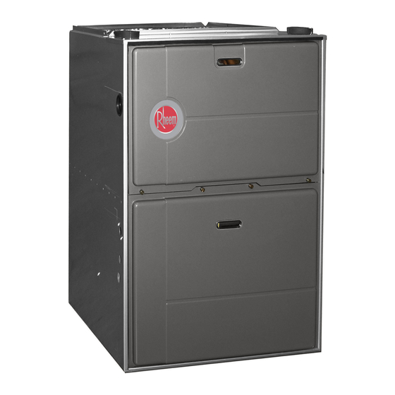
Page 4: General Information
GENERAL INFORMATION FIGURE 1 UPFLOW AIR HANDLER THE RWHB SERIES HYDRONIC AIR HANDLERS ARE DESIGN-CERTIFIED BY UL ITEM ITEM NO. PART NAME NO. PART NAME DOOR SWITCH PUMP JUNCTION BOX WATER INLET TRANSFORMER WATER OUTLET CAPACITOR BLOWER MOTOR LOW VOLTAGE (THERMOSTAT) TERMINAL HYDRONIC COIL ASSEMBLY BLOWER... - Page 5 IMPORTANT required for the job specification. NOTICE • Read the entire instructions before INFORMATION ABOUT IMPROPER INSTALLATION, OR starting the installation. EFFICIENCY AND INDOOR INSTALLATION NOT MADE IN • Some building codes require extra ACCORDANCE WITH THE UL AIR QUALITY cabinet insulation and gasketing CERTIFICATION OR THESE when unit is installed in attic...
-
Page 6: Location Requirements And Considerations
LOCATION REQUIREMENTS AND CONSIDERATIONS GENERAL INFORMATION IMPORTANT: Support this unit CLEARANCE - when installed. Since this air ACCESSIBILITY 1. IMPORTANT: If installing the unit handler is suitable for attic or over a finished ceiling or living crawl space installations, it may The design of air handlers with input area, be certain to install an be installed on combustible wood... - Page 7 FIGURE 4 CLEARANCE TO COMBUSTIBLES, UPFLOW, HORIZONTAL LEFT OR RIGHT, IMPORTANT: Support this unit when installed. Since this air handler is suitable for attic or crawl space installation, it may be NO DOWNFLOW installed on combustible wood flooring or by using support brackets.
-
Page 8: Selection Procedure
36 = [519-613.5 L/s] P = PSC 60,000 [17.6 kW] [279 x 178 mm] 48 = 1500-1700 CFM R = Rheem H = ir handler W = Water B = 2nd Series - Rev 0 X = ECO 48 = [707.9-802.3 L/s]... - Page 9 HYDRONIC AIR HANDLER ELECTRICAL PHYSICAL SPECIFICATIONS - PSC MODELS U.S. and Canadian Models MODEL NUMBERS RHWB-04WMP36A RHWB-06WMP48A RHWB-08WRP60A RHWB-10WRP60A Nominal Heating Capacity BTU/hr [W] 40000 60000 80000 100000 ir Side Temperature Rise* °F [°C] 45-75 [25-41.7] 40-70 [22.2-38.9] 35-65 [19.4-36.1] 35-65 [19.4-36.1]...
- Page 10 SAMPLE HYDRONIC AIR HANDLER PERFORMANCE SAMPLE HYDRONIC AIR HANDLER PERFORMANCE WATER FLOW WATER INLET AIR CFM CAPACITY AIR TEMP WATER OUTLET AIR INLET AIR OUTLET TEMP (°F) [°C] TEMP (°F) [°C] TEMP (°F) [°C] TEMP (°F) [°C] [L/s] (BTU/HR) [kW] RISE (°F) [°C] LB/HR 120 [49]...
- Page 11 HYDRONIC AIR HANDLER TANKLESS WATER HEATER PERFORMANCE Capacity (BTU/HR) [kW] Entering Water Temperature (°F) )°C) Heating Air Tankless Air Handler Model Blower Speed Delivery 120 [49] 130 [54] 140 [60] 150* [65] 160 [71] Model (In. W.C.) (CFM) [L/s] RTG-64 26400 [7.74] 31800 [9.32] 35500 [10.40] RTG-84 25700 [7.53] 30900 [9.06]...
-
Page 12: Ducting
DUCTING NOTE: Where the maximum air flow HORIZONTAL UNIT is 1800 CFM or more, both sides or Proper air flow is required for the 1. Position the unit to minimize long the bottom must be used for return correct operation of this air handler. runs or runs with many turns and air. - Page 13 FIGURE 6 UPFLOW Blower located below coil POSITION ORIENTATION section. Conditioned air is discharged upward. HORIZONT L LEFT HORIZONT L RIGHT Blower located to the right of Blower located to the left of coil coil section. Conditioned air is section. Conditioned air is discharged to the left.
-
Page 14: Installation
INSTALLATION SUSPENDED CABINET Attachment Methods Using Straps WARNING Method 1 INSTALLATION IT IS THE INSTALLER’S RESPONSIBILITY TO USE AN Use (4) #8 x 3/4 sheet metal screws If the cabinet cannot be supported on a APPROPRIATE HANGING METHOD for each strap. The straps should be Refer to the specification section of this frame or supported from the wall, it may CAPABLE OF SUPPORTING THE... -
Page 15: Plumbing
PLUMBING Hydronic Resistance of Furthermore, two pressure taps will Fittings, Valves, and Other need to be installed, the first located Codes: Devices: between the air handler outlet and the The RHWB air handler is used in adjustable valve as near as possible to Before the total hydronic resistance potable water systems. - Page 16 = .3 ft. 2 (3/4”) Ball Valve 2 (.2) = .4 ft. Total Equivalent Length ..= 57 ft. FIGURE 9 EQUIVALENT LENGTH CALCULATION Rheem Tankless Water Heater COLD 3 FT 1 FT 1-1/2 FT 1 FT...
- Page 17 Open-Loop System STEP 6: CLOSE drain valve 3 (DV STEP 3: OPEN drain valve 3 (DV ) to which a hose MUST be connected and STEP 7: OPEN ball valve 3 (BV If piping is done in accordance with the draining to a sink, drain or outdoors.
-
Page 18: Electrical Wiring
ELECTRICAL WIRING jurisdiction. USE COPPER WIRE THERMOSTAT ONLY. Provide separate branch electric The room thermostat must be com- circuit with field supplied disconnect patible with the integrated air handler switch. WARNING control on the air handler. Generally, Location of disconnect switch to be in all thermostats that are not of the TURN OFF ELECTRIC POWER AT clear site, accessible and in close... - Page 19 FIGURE 11 FIELD WIRING DIAGRAM Single Stage Thermostat 5 Wire Field 115, 208 / 230 Volt Wiring 3 Wire Heating Only Field 24 Volt Wiring Factory 24 Volt Wiring AIR HANDLER Factory 115 Volt Wiring Junction Box Control Box Condensing Unit 24 Volt Terminal Block Flow Sensor 24 Volt FS / WH Connector...
- Page 20 System Low Voltage Wiring Dip Switch Options: • close to or in a frequently used Diagrams room, preferably on an inside, Refer to the appropriate diagram for the partitioning wall proper dip switch setting to be used with NOTE: Local codes may require the designed application (Figure 17).
- Page 21 • exposed to direct light and heat from START-UP PROCEDURE START-UP PROCEDURE a lamp, sun, fireplace, or other heat- (HEATING ONLY): (COOLING SYSTEM) radiating object which may cause a The following conditions must be met Refer to field-supplied evaporator coil false reading.
-
Page 22: Sequence Of Operation
SEQUENCE OF OPERATION BLOWER TIME DELAY (HEATING ROOM THERMOSTAT COOLING OR COOLING) (ANTICIPATOR SETTING) Single Stage Cooling • When the thermostat calls for cooling All models are equipped with a blower See instructions with outdoor section, (Y), there is a 1 second delay then time delay (BTD) in lieu of a blower relay condensing unit or heat pump for the control energizes the high blower... -
Page 23: Changing Blower Speed
TABLE 6 HYDRONIC AIR HANDLER AIR FLOW PERFORMANCE - RHWB CFM [L/s] Air Delivery External Static Pressure Inches Water Column [kPa] Blower / Motor HP Model Inches [mm] Speed 0.1 [.02] 0.2 [.05] 0.3 [.07] 0.4 [.10] 0.5 [.12] 0.6 [.15] 0.7 [.17] 0.8 [.19] 0.9 [.22] 1.0 [.24] 794 [375] 775 [366] 749 [353] 719 [339] 686 [324] 655 [309] 621 [293] 590 [278] 534 [252] 473 [223] 11 x 7 M-Lo... -
Page 24: Maintenance
MAINTENANCE TABLE 7 FILTER SIZES WARNING UPFLOW FILTER SIZES AIR HANDLER INPUT BOTTOM SIDE QUANTITY THESE INSTRUCTIONS ARE WIDTH MBTU/HR SIZE SIZE INTENDED AS AN AID TO " 45, 60 " X 25" " X 25" QUALIFIED SERVICE " 80, 100 "... -
Page 25: Troubleshooting
FIGURE 17 FILTER LOCATIONS UPFLOW UPFLOW JACKET ONLY JACKET ANGLE DRILL (2) JACKET 3/16" DIA. HOLES ANGLE DETAIL ATTACH WITH SHEET METAL 8.000 SCREWS (2 REQÕD) 4.875 FILTER ROD FILTER ROD SUPPORT SUPPORT ANGLE ANGLE 1.531 FILTER SUPPORT FILTER SUPPORT ANGLE ANGLE (SEE ANGLE DETAIL) - Page 26 FIGURE 18 GENERAL TROUBLESHOOTING CHART General Trouble Shoo ng Chart General Troubleshooting Chart Warning: Disconnect all power to unit before servicing. Failure to shut off power can cause electrical shock resul ng in personal injury or death. c i r a t l i l a a t l...
-
Page 27: Wiring Diagrams
FIGURE 19 ELECTRICAL WIRING DIAGRAM – PSC MODELS... - Page 28 FIGURE 20 ELECTRICAL WIRING DIAGRAM – ECO TECH™ MODELS CM 0313...
Need help?
Do you have a question about the RHWB-04WMP36A and is the answer not in the manual?
Questions and answers