TP-Link TL-SG5428 Installation Manual
Hide thumbs
Also See for TL-SG5428:
- User manual (257 pages) ,
- Cli reference manual (239 pages) ,
- Reference manual (216 pages)

Related Manuals for TP-Link TL-SG5428


Summary of Contents for TP-Link TL-SG5428
- Page 1 Business Networking Solution Installation Guide L2 Managed Switch TL-SG5428/TL-SG5412F...
-
Page 2: Fcc Statement
No part of the specifications may be reproduced in any form or by any means or used to make any derivative such as translation, transformation, or adaptation without permission from TP-LINK TECHNOLOGIES CO., LTD. Copyright © 2015 TP-LINK TECHNOLOGIES CO., LTD. All rights reserved. - Page 3 The User Guide and CLI Reference Guide of the product are provided on the resource To obtain the latest product information, please visit the Official Website: http://www.tp-link.com About this Installation Guide This Installation Guide describes the hardware characteristics, installation methods and the points that should be attended to during installation.
- Page 4 Conventions Due to the similarity in the structure of the L2 Managed Switch series, in this Installation Guide we take TL-SG5428 as an example to illustrate Chapter 2 Installation, Chapter 3 Lightning Protection and Chapter 4 Connection. This guide uses the specific formats to highlight special messages. The following table lists the notice icons that are used throughout this guide.
-
Page 5: Table Of Contents
Contents Chapter 1 Introduction ———————————— 01 Product Overview .........01 Appearance ..........01 Chapter 2 Installation ————————————— 04 Package Contents .........04 Safety Precautions ........04 Installation Tools ..........06 Product Installation ........06 Chapter 3 Lightning Protection ———————— 08 Cabling Reasonably ........08 Connect to Ground ........10 Equipotential Bonding ........11 Use Lightning Arrester ........12 Chapter 4 Connection —————————————... -
Page 6: Chapter 1 Introduction
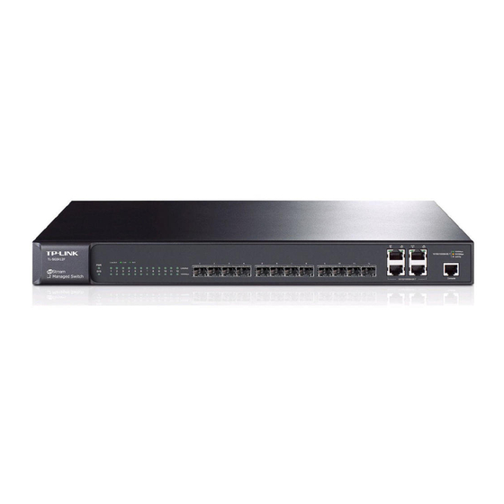
1.1 Product Overview TL-SG5428 and TL-SG5412F are Gigabit Ethernet switching products recently developed by TP-LINK. TL-SG5428 possesses 24 RJ45 ports and 4 SFP slots, while TL-SG5412F characterizes with 12 SFP slots and 4 RJ45 ports. The SFP slot enables remote connection with SFP slots on other devices through SFP module and fiber. - Page 7 ■ lighten only when a 1000Mbps device is connected to the corresponding port. For TL-SG5428, the SFP ports are individual, while for TL-SG5412F, the four RJ45 ports ■ combind with four SFP ports are combo ports, which means that the SFP port with the corresponding RJ45 port cannot work simultaneously.
- Page 8 Designed to connect with the serial port of a computer or terminal for monitoring and configuring the Switch. Rear Panel ■ Due to the similarity of TL-SG5428 and TL-SG5412F in the rear panel, here TL-SG5428 is used as an example. Grounding Terminal Power Socket...
-
Page 9: Chapter 2 Installation
This Installation Guide Console Cable TL-SG5 Two mounting brackets and One Resource CD the fittings TL-SG5428 2.2 Safety Precautions To avoid any device damage and bodily injury caused by improper use, please observe the following rules. Safety Precautions ■ Keep the power off during the installation. - Page 10 -40℃ ~ 70℃ 5% ~ 90%RH Non-condensing Clearness TL-SG5428 The dust accumulated on the Switch can be absorbed by static electricity and result in poor contact of metal contact points. Some measures have been taken for the device to prevent static electricity, but too strong static electricity can cause deadly damage to the electronic elements on the internal circuit board.
-
Page 11: Installation Tools
Note: For detailed lightning protection measures, please refer to Chapter 3 Lightning Protection. Installation Site TL-SG5428 When installing the device on a rack or a flat workbench, please note the following items: The rack or workbench is flat and stable, and sturdy enough to support the weight of ■... -
Page 12: Rack Installation
L2 Managed Switch 3. Turnover the device and attach the supplied rubber feet to the recessed areas on the bottom at each corner of the device. Feet Bottom of the Device Notch Figure 2-1 Desktop Installation Rack Installation ■ To install the device in an EIA standard-sized, 19-inch rack, follow the instructions described below: 1. -
Page 13: Chapter 3 Lightning Protection
L2 Managed Switch Chapter 3 Lightning Protection 3.1 Cabling Reasonably In the actual network environment, you may need cable outdoors and indoors, and the requirements for cabling outdoors and indoors are different. A reasonable cabling system can decrease the damage of induced lightning to devices. Note: It’s not recommended using Ethernet cables outdoors. - Page 14 L2 Managed Switch Requirements for the distance between Ethernet cable and other pipelines are shown ■ in the table. Ethernet Cable Other Pipelines Min Parallel Net Length Min Parallel-overlapping Net Height L (mm) H (mm) Down-conductor 1000 Service pipe Compressed air pipe Thermal pipe (not wrapped) 500 Thermal pipe (wrapped) Gas pipe...
-
Page 15: Connect To Ground
L2 Managed Switch 3.2 Connect to Ground Connecting the device to ground is to quickly release the lightning over-voltage and over-current of the device, which is also a necessary measure to protect the body from electric shock. In different environments, the device may be grounded differently. The following will instruct you to connect the device to the ground in two ways, connecting to the grounding bar or connecting to the ground via the power cord. -
Page 16: Equipotential Bonding
L2 Managed Switch Note: The figure is to illustrate the application and principle. The power cord you get from ■ the package and the socket in your situation will comply with the regulation in your country, so they may differ from the figure above. If you intend to connect the device to the ground via the PE (Protecting Earth) ■... -
Page 17: Use Lightning Arrester
If it is not matched, this signal lighting arrester will not work. Purchase a standard lightning arrester. Install signal lightning arrester near the protected device and connect it to the ■ ground via a shorter ground cable. TL-SG5428 Grounding Terminal Equipotential Bonding Cable Ethernet Cable Signal Lightning Arrester... -
Page 18: Chapter 4 Connection
L2 Managed Switch Chapter 4 Connection 4.1 Ethernet Port Connect the Ethernet ports of the switch to the network devices by RJ45 cable as the following figure shows. RJ45 Port RJ45 Cable TL-SG 5428 Figure 4-1 Connecting the RJ45 Port 4.2 SFP Port Connect the SFP port to a SFP module. - Page 19 Figure 4-3 SFP module The following table shows the detailed information of two SFP modules (TL-SM311LS and TL-SM311LM) produced by TP-LINK, which makes you have a round idea about it so as to give you a reference for choosing the suitable SFP module.
-
Page 20: Console Port
L2 Managed Switch 4.3 Console Port CLI (Command Line Interface) enables you to manage the switch, thus you can load the CLI after connecting the PCs or Terminals to the console port on the switch via the provided cable. Connect the console port of the device with your computer by the console cable as the following figure shows. -
Page 21: Initialization
L2 Managed Switch Figure 4-5 Connecting to Power Supply Note: The figure is to illustrate the application and principle. The power cord you get from the package and the socket in your situation will comply with the regulation in your country, so they may differ from the figure above. 4.6 Initialization After the device is powered on, it begins the Power-On Self-Test. -
Page 22: Chapter 5 Configuration
L2 Managed Switch Chapter 5 Configuration 5.1 Configure the switch via GUI 1. To access the GUI of the switch, open a web browser and type the default management address http://192.168.0.1 in the address field of the browser, then press the Enter key. Figure 5-1 Web Browser Note: To log on to the GUI of the switch, the IP address of your PC should be set in the same subnet addresses of the switch. -
Page 23: Configure The Switch Using Cli
Stop bits: 1 ■ Flow control: none ■ 4. The DOS prompt ”TP-LINK>” will appear after pressing the Enter button as Figure 5-8 shown. It indicates that you can use the CLI now. Figure 5-4 Log in the switch Logon by Telnet ■... - Page 24 L2 Managed Switch 2. Make sure the switch and the PC are in the same LAN. Click Start and type in cmd in the Search programs and files window and press the Enter button. Figure 5-5 Run window 3. Type telnet 192.168.0.1 in the command prompt shown as Figure 5-6, and press the Enter button.
-
Page 25: Appendix A Troubleshooting
L2 Managed Switch Appendix A Troubleshooting What could I do if I forgot the username and password of the switch? 1. Connect the console port of the PC to the console port of the switch and open hyper terminal. 2. Power off and restart the switch. When you are prompted that “Press CTRL-B to enter the bootUtil”... -
Page 26: Appendix B Hardware Specifications
L2 Managed Switch Appendix B Hardware Specifications Item Content IEEE 802.3 10Base-T IEEE 802.3u 100Base-TX IEEE 802.3ab 1000Base-T Standards IEEE 802.3z 1000Base-X IEEE 802.3x Flow Control 10Base-T: UTP/STP of Cat. 3 or above (≤100m) 100Base-TX: 2-pair UTP/STP of Cat. 5 or above (≤100m) 1000Base-T: 4-pair UTP/STP of Cat. - Page 28 Website: http://www.tp-link.com Tel: +86 755 26504400 E-mail: support@tp-link.com 7106505361 REV2.0.3...