Harman Kardon AVR 240 Owner's Manual
Hide thumbs
Also See for AVR 240:
- Service manual (156 pages) ,
- Owner's manual (64 pages) ,
- Quick start manual (4 pages)

Related Manuals for Harman Kardon AVR 240


Summary of Contents for Harman Kardon AVR 240
- Page 1 ® Power for the Digital Revolution ® AVR 240 AUDIO/VIDEO RECEIVER OWNER’S MANUAL DIGITAL LOGIC 7 VID 1 PRO LOGIC VID 2 3 STEREO VID 3 FMAM 5 7 CH. STEREO VID 4 TAPE 6 8 CH SURR. OFF Optical 3...
-
Page 2: Table Of Contents
AVR 240 AUDIO/VIDEO RECEIVER Introduction For Canadian model Important Safety Information This class B digital apparatus complies with Canadian Unpacking ICES-003. Front-Panel Controls For models having a power cord with a polarized plug: Rear-Panel Connections CAUTION: To prevent electric shock, match wide blade Remote Control Functions of plug to wide slot, fully insert. -
Page 3: Introduction
7.1 and 5.1 processing in crosstalk component video switching. The AVR 240 has been engineered so that it is easy ® a variety of modes, and two modes of VMAx to take advantage of all the power of its digital tech-... -
Page 4: Important Safety Information
I Consult the dealer or an experienced radio/TV the unit, or place objects directly over them. I Due to the weight of the AVR 240 and the heat Handle the AC Power Cord Gently technician for help. When disconnecting the power cord from an AC out- generated by the amplifiers, there is the remote This device complies with Part 15 of the FCC Rules. -
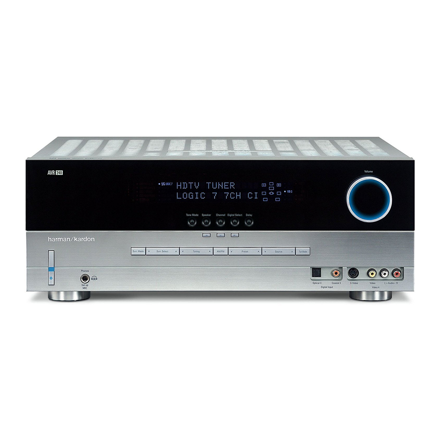
Page 5: Front-Panel Controls
Switch 1 is “ON, ” press this button to turn on the channel materials, it is recommended that you leave AVR 240; press it again to turn the unit off. The Power To change the bass or treble settings, make sure that these settings at the results obtained during the config- Indicator 2 turns blue when the unit is on. - Page 6 (e.g., Dolby, DTS, DTS Neo:6, Logic 7, DSP, Stereo). to enter the desired setting into the AVR 240’s memory. Channel Adjust Selector: Press this button to When the button is pressed so that the name of the...
- Page 7 FRONT-PANEL CONTROLS operation, this line will show current input source and which analog or digital input is in use. When the tuner is the input, this line will identify the station as AM or FM and show the frequency and preset number, if any. ı...
-
Page 8: Rear-Panel Connections
¡ FM Antenna Jack: Connect the supplied indoor £ Tape Outputs: Connect these jacks to the ∞ Remote IR Input: If the AVR 240’s front-panel (or an optional external) FM antenna to this terminal. RECORD/INPUT jacks of an audio recorder. - Page 9 PLAY/OUT S-video jack on HDTV set-top converter, satellite receiver or other right) (+) terminals on the AVR 240 to the red (+) that unit and then make certain that the S-Video video source device with component video outputs to terminals on the speakers and the black (–) terminals...
- Page 10 NOTE ON VIDEO CONNECTIONS: When connecting a video source product such as a VCR, DVD player, satellite receiver, cable set-top box, personal video recorder or video game to the AVR 240, you may use either a composite or S-video connection, but not both.
-
Page 11: Remote Control Functions
6-Channel/8-Channel Direct Input f Mute NOTES: • The function names shown here are each button’s feature when used with the AVR 240. Most buttons have additional functions when used with other ® devices. See pages 44–45 for a list of these functions. - Page 12 ⁄ ¤ Buttons n again, to change the level setting. (See the AVR 240 is in the Standby mode, it will also turn the pages 29 and 38 for more information.) However, AVR 240 on. Harman Kardon recommends that you first perform...
- Page 13 Logic 7 Mode Select Button: Press this button of commands stored in the remote. (See page 41 for for the AVR 240, but may be used by other devices. to select from among the available Logic 7 surround more information on storing and recalling macros.) b Volume Up/Down: Press these buttons to raise modes.
- Page 14 , pressing this selector will select the iPod as the audio source input device for the AVR 240. In addition, if a video display is connected to one of the Video Monitor Outputs cV, the iPod’s messages will appear on screen, and in the Upper and Lower Display Lines PQ.
-
Page 15: Installation And Connections
Questions about these jacks, we recommend connecting your video Outputs ·a on the rear panel of the AVR 240 to running cables inside walls should be referred to your recorder so that you may take advantage of the... -
Page 16: System And Power Connections
Audio/Video and S-Video Input Jacks RZ. other audio/video device, such as a DVD-Audio or The AVR 240 is designed for flexible use with external Although any video device may be connected to SACD player or HDTV set-top box, to the Video 1, control components. -
Page 17: System Configuration
SYSTEM CONFIGURATION When all audio, video and system connections have close to the top (or bottom) of the video screen as option when room conditions prevent the use of side- been made, the final steps before listening to your new possible so that when you position the front left/right mounted surround speakers. - Page 18 Front Right Front Left enjoy the benefits of advanced surround modes such Speaker Speaker as Dolby Digital EX, DTS-ES and Harman Kardon’s proprietary Logic 7/7.1 processing. 30° 30° To step up to a 6.1 system, first place the speakers for a 5.1 system, as shown on page 14. The “sixth”...
-
Page 19: System Setup
50 seconds You are now ready to power up the AVR 240 to begin The on-screen menus are not available when a com- by going to the ADVANCED SELECT menu, these final adjustments. -
Page 20: Input Setup
Use the ‹/› Buttons o to move guesswork out of speaker size and delay settings, and The first step in configuring the AVR 240 is to configure from one character to the previous or following char- balances the speaker output levels to tailor the AVR’s each input. -
Page 21: Surround Setup
– you may change it later. The Bridge will remain lit when the AVR 240 is in However, to make it easier to establish the initial... - Page 22 SYSTEM CONFIGURATION the AVR 240 will not appear unless a digital source is ing both the Dolby Digital mode and the second * DOLBY SURROUND * mode, separated by a plus sign (e.g., DOLBY selected and is playing the correct bitstream. Remember D+DOLBY PRO LOGIC II MUSIC).
-
Page 23: Automated Speaker Setup Using Ezset
Hall 1, Hall 2, Theater, VMAx Near and VMAx The AVR 240 is one of the first receivers in its class to system and the program in use. Far. The Hall and Theater modes are designed for offer automated speaker setup and system calibration. - Page 24 M E A S U R E M E N T S T O P quiet as possible. After 5 seconds, the screen will AVR 240’s Headphone Jack 4, making certain S E T T I N G L E V E L change again to display the main EzSet+ menu that the mini-plug to 1/4"...
-
Page 25: Manual Setup
EzSet+, follow the instructions on the following pages. SETTINGS, allowing you the option of selecting This menu tells the AVR 240 which type of speakers YES or NO. Unplug the microphone and store it in are in use. This is important as it adjusts the settings... - Page 26 You will first need to access the SPEAKER speaker definitions shown below. to be active once, and the AVR 240 will set them as SIZE submenu. With the MANUAL SETUP active for all surround modes and sources. If you wish submenu on screen, the ›...
- Page 27 SYSTEM CONFIGURATION • If no subwoofer is connected to the AVR 240, NOTE: When the INDEPENDENT setting is S P E A K E R X - O V E R Buttons o on the remote so press the ‹...
-
Page 28: Delay Settings
In addition to adjusting the delay time for each individ- MENU, and press the ¤ together. We recommend that this adjustment be ual speaker position, the AVR 240 allows you to adjust cursor is pointing at the MANUAL on-screen ›... -
Page 29: Output Level Adjustment
(see Figure 15). tion of any surround sound product. It is particularly speakers to the same volume level. When one of important for a digital receiver such as the AVR 240, Buttons o is pushed, the test noise ‹... - Page 30 Once the settings outlined on the previous pages have NOTE: The subwoofer level is not adjustable when the been made, the AVR 240 is ready for operation. While normal test tone is in use. The subwoofer output level there are some additional settings to be made, these...
-
Page 31: Operation
• When using the AVR 240 for the first time, you must turn the unit off with the front-panel Main Power battery may be charged. -
Page 32: Surround Mode Selection
DSP Surround Off mode has When the DSP icon is not lit in Surround Off mode One of the important features of the AVR 240 is its been selected, or when post-processing is being used with an analog audio input in use, the AVR is in analog... -
Page 33: Surround Mode Chart
6.1-channel presentation in movie or music mode. Logic 7 Cinema Exclusive to Harman Kardon for A/V receivers, Logic 7 is an advanced mode that extracts the maximum surround information Logic 7 Music from either surround-encoded programs or conventional stereo material. - Page 34 OPERATION Dolby Virtual Speaker Dolby Virtual Speaker uses advanced technology to simulate the sonic signature of a speaker location even when there is no speaker physically Reference present in that location. The Reference (“REF”) mode activates any missing speakers to simulate a 5.1 presentation with accurate localization. Wide The Wide mode virtualizes the locations of the front-channel speakers to create a wider image and a more enveloping sound field.
- Page 35 If you have not already configured an input for a digital • A “1” tells you that there is only a single, surround- use the AVR 240 to listen to the Dolby Digital sound- source using the on-screen menus as shown on page encoded surround channel.
- Page 36 AVR 240. To listen to a PCM digital source, first select the input for feed to the AVR 240. It is also possible for the type • Not all digitally encoded programs contain full 5.1- the desired source (e.g., CD). Next press the Digital of signal feed to change during the course of a DVD or 6.1-channel audio.
-
Page 37: Tuner Operation
Display Line ı and goes out. This will also Unauthorized duplication of copyrighted materials Tuner Operation is prohibited by federal law. activate manual tuning mode. The AVR 240’s tuner is capable of tuning AM, FM and Using Bridge Preset Tuning FM Stereo broadcast stations. Stations may be tuned Using the remote, up to 30 stations may be stored in When Harman Kardon’s... -
Page 38: Output Level Trim Adjustment
When all adjust- mode and following the instructions shown above. ments have been made and no further adjustments are made for five seconds, the AVR 240 will return to Memory Backup normal operation. This product is equipped with a memory backup sys-... -
Page 39: Advanced Features
The semi-OSD system is helpful in that it While it is not necessary to use these features to the AVR 240 is turned on, it will always return to the provides feedback on any control changes or remote operate the unit, they do provide additional options. - Page 40 If you have no other adjustments to make, press the OSD Button v to exit the menu system. The AVR 240 allows you to set the unit so that it will either respond to the default or switch to your desired mode.
-
Page 41: Programming The Remote
The AVR 240 remote is factory-programmed for all AVR of the code. One blink is the number 1, two blinks is If the unit you wish to include in the AVR 240’s remote functions, as well as those of most Harman Kardon CD the number 2, and so forth. -
Page 42: Programmed Device Functions
Function List and then look in the column for the device Power On command. you are controlling. For example, button number 46 is the Direct button for the AVR 240, but it is the • Press the Sleep/Channel Up Button j to “Favorite” button for many cable television boxes complete the process and store the macro and satellite receivers. -
Page 43: Volume Punch-Through
AVR 240’s volume activated, although the remote same Input Selector in Steps 1 and 3. for the device that will be used to change the is set to run the TV. Either the AVR 240 or TV volume Before programming the remote for Volume, Channel •... -
Page 44: Function List
FUNCTION LIST Button Name AVR Function CD/CD-R Tape VCR (VID1) CBL (VID2) SAT (VID2) TV (VID3) Bridge (DMP) Power On Power On Power On Power On Power On Power On Power On Power On Power On Power Off Power Off Power Off Power Off Power Off... - Page 45 FUNCTION LIST Button Name AVR Function CD/CD-R Tape VCR (VID1) CBL (VID2) SAT (VID2) TV (VID3) Bridge (DMP) Tuning Up Tuning Up Next Chapter Track Direct Cancel Cancel Sleep Album + Direct Direct Tuner Entry Angle Random Play Clear Clear Clear Clear Clear...
-
Page 46: Setup Code Tables
CENTURION CENTRONIC CITIZEN CLASSIC CONCERTO CONTEC CORANDO CORONADO CRAIG CROWN CURTIS MATHES DAEWOO DAYTRON DIGI LINK DYNASTY DYNATECH ELECTROHOME EMERSON FUNAI FUTURETECH GOLDSTAR/LG GRUNDIG HALL MARK HARMAN KARDON HITACHI INFINITY INKEL JC PENNEY JENSEN KAWASHO KENWOOD LLOYTRON LODGENET SETUP CODES... - Page 47 SETUP CODE TABLE: TV Manufacturer/Brand Setup Code Number LOGIK LUXMAN MAGNAVOX MARANTZ MATSUI MEMOREX METZ MINERVA MITSUBISHI NATIONAL NIKEI ONKING ONWA OPTONICA ORION PANASONIC PHILCO PHILIPS PIONEER PORTLAND PROSCAN PROTON QUASAR RADIO SHACK REALISTIC RUNCO SAMPO SAMSUNG SANYO SCOTT SEARS SHARP SIEMENS SIGNATURE...
- Page 48 SETUP CODE TABLE: TV Manufacturer/Brand Setup Code Number TEKNIKA TELERENT TERA THOMSON TOSHIBA TOTEVISION VIDEO CONCEPTS VIDTECH WARDS YAMAHA YORK YUPITERU ZENITH ZONDA SETUP CODES...
- Page 49 DAYTRON 018 048 DYNATECH EMERSON 013 040 042 110 112 FISHER FUNAI 076 095 124 GO VIDEO GOLDSTAR/LG 018 107 HARMAN KARDON 018 049 HITACHI 040 048 JC PENNEY 018 045 JENSEN 018 048 111 132 KENWOOD 020 048 LLOYD...
- Page 50 SETUP CODE TABLE: VCR Manufacturer/Brand Setup Code Number SALORA SAMSUNG 045 051 095 105 109 SANSUI 048 116 147 SANYO 017 020 SCOTT 110 112 SEARS 017 020 SHARP 129 156 SONY 080 129 SOUNDESIGN SYLVANIA SYMPHONIC TANDY 017 040 TASHICO TATUNG TEAC...
- Page 51 CAPETRONIC CARRERA CARVER 143 144 145 185 186 CASIO CLARINETTE DENON EMERSON FISHER FRABA FUNAI GENEXXA GOLDSTAR/LG HAITAI HARMAN KARDON 054 190 HITACHI INKEL JC PENNEY JENSEN KENWOOD 079 148 151 176 178 LOTTE LUXMAN MAGNAVOX MARANTZ 192 193 MCINTOSH...
- Page 52 061 135 YORK SETUP CODE TABLE: DVD Manufacturer/Brand Setup Code Number APEX DIGITAL DENON 019 051 003 004 GOLDSTAR/LG 005 055 064 066 HARMAN KARDON 001 002 MAGNAVOX MARANTZ MITSUBISHI ONKYO 009 048 PANASONIC 024 030 044 PHILIPS PIONEER 041 065...
- Page 53 SETUP CODE TABLE: SAT Manufacturer/Brand Setup Code Number ALPHASTAR ALPHASTAR DBS ALPHASTAR DSR BIRDVIEW CHANNEL MASTER 320 321 CHAPARRAL 315 316 CITOH DRAKE 313 317 413 481 DX ANTENNA 331 352 ECHOSTAR 395 397 453 463 477 478 ELECTRO HOME FUJITSU 324 329 GENERAL INSTRUMENT...
- Page 54 SETUP CODE TABLE: TAPE Manufacturer/Brand Setup Code Number HARMAN KARDON SETUP CODE TABLE: CBL Manufacturer/Brand Setup Code Number 001 011 ALLEGRO AMERICAST ARCHER BELCOR CABLE STAR 033 113 CITIZEN COLOUR VOICE 085 090 DIGI EAGLE EASTERN 066 070 ELECTRICORD EMERSON FOCUS G.I.
- Page 55 SETUP CODE TABLE: CBL Manufacturer/Brand Setup Code Number REMBRANT SAMSUNG 003 072 186 SCIENTIFIC ATLANTA 183 203 221 222 SEAM SIGNATURE 001 188 SPRUCER 053 081 177 189 STARCOM 002 011 163 STARGATE TANDY TELECAPATION TEXSCAN TIMELESS TOCOM 170 205 UNITED CABLE UNIVERSAL 033 034 039 042 113...
-
Page 56: Troubleshooting Guide
• Check that Digital Input is selected In addition to the items shown above, additional information on troubleshooting possible problems with your AVR 240, or installation-related issues, may be found in the list of “Frequently Asked Questions” which is located in the Product Support section of our Web site at www.harmankardon.com. -
Page 57: Technical Specifications
±35 Amps All features and specifications are subject to change without notice. Transient Intermodulation Distortion (TIM) Unmeasurable Harman Kardon, Harman International, Power for the Digital Revolution and Logic 7 are registered trademarks, Slew Rate 40V/µsec are trademarks, and The Bridge and of Harman International Industries, Incorporated. -
Page 58: Index
INDEX 5-Channel Stereo 23, 34 Front-Panel Controls 5–7 Settings Worksheet 59 6-Channel/8-Channel Direct Input 9, 15, 31 Front-Panel Jacks 6, 16, 31, 32 Sleep Mode 12, 31 7-Channel Stereo 23, 34 Front-Panel-Display Fade 39 Source Selection 6, 12, 20, 31 AC Power Connections 9, 16 Full OSD 19, 39–40 Speaker Crossover Menu 27... -
Page 59: Appendix - Settings Worksheet
APPENDIX – SETTINGS WORKSHEET Table 1: Input Settings FEATURE VIDEO 1 VIDEO 2 VIDEO 3 DMP CD TAPE TUNER 6/8 CH. DIRECT Bridge Input Title –––––––– Component Video Input Component Component Component Component Component Component Component Component –––––––––– Video 1 (Y/N) Video2 (Y/N) Video 2 (Y/N) Video 2 (Y/N) Video 1 (Y/N) Video 1 (Y/N) Video 1 (Y/N) Video 2 (Y/N) - Page 60 ® 250 Crossways Park Drive, Woodbury, New York 11797 www.harmankardon.com © 2005 Harman International Industries, Incorporated. All rights reserved. Part No. CQX1A1026Z 8/05...