Table of Contents
Advertisement
Available languages
Available languages
Quick Links
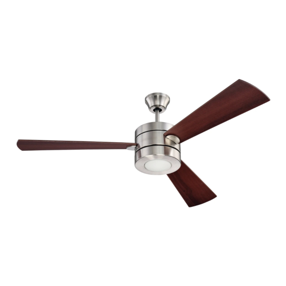
Triad
Installation Guide
For Models:
TRI54BNK3
TRI54ESP3
E192641
net weight of fan: 18.63 lb (8.47 kg)
READ THESE INSTRUCTIONS AND
SAVE THEM FOR FUTURE USE
Table of Contents:
Safety Tips. pg. 1
Unpacking Your Fan. pg. 2
Parts Inventory. pg. 2
Installation Preparation. pg. 3
Hanging Bracket Installation. pg. 3
Fan Assembly. pgs. 4 - 5
Wiring. pgs. 5 - 6
Canopy Assembly. pg. 7
Blade Assembly. pg. 7
Wall Control Operation. pg. 9
Remote Control Operation. pg. 10
Testing Your Fan. pg. 10
Troubleshooting. pg. 11
Warranty. pg. 11
Parts Replacement. pg. 11
PRINTED IN CHINA
Advertisement
Chapters
Table of Contents

Subscribe to Our Youtube Channel
Related Manuals for Ellington TRI54BNK3


Summary of Contents for Ellington TRI54BNK3
-
Page 1: Table Of Contents
READ THESE INSTRUCTIONS AND SAVE THEM FOR FUTURE USE Triad Installation Guide For Models: TRI54BNK3 Table of Contents: Safety Tips. pg. 1 TRI54ESP3 Unpacking Your Fan. pg. 2 Parts Inventory. pg. 2 Installation Preparation. pg. 3 Hanging Bracket Installation. pg. 3 Fan Assembly. -
Page 2: Safety Tips
SAFETY TIPS. WARNING: To reduce the risk of electrical shock, turn off the electricity to the fan at the main fuse box or circuit panel before you begin the fan installation or before servicing the fan or installing accessories. READ ALL INSTRUCTIONS AND SAFETY INFORMATION CAREFULLY BEFORE INSTALLING YOUR FAN AND SAVE THESE INSTRUCTIONS. -
Page 3: Unpacking Your Fan
1. Unpacking Your Fan. Carefully open the packaging. Remove items from Styrofoam inserts. Remove motor housing and place on carpet or Styrofoam to avoid damage to finish. *The motor stabilization pieces may be dicarded at this time. Do not discard fan carton or Styrofoam inserts should this fan need to be returned for repairs. -
Page 4: Installation Preparation
3. Installation Preparation. blade edge To prevent personal injury and damage, inches 7 feet (76cm) ensure that the hanging location allows the (2.13m) blades a clearance of 7 feet (2.13m) from the floor and 30in. (76cm) from any wall or 12ft - 20ft obstruction. -
Page 5: Fan Assembly. Pgs
set screw 5. Fan Assembly. stop pin Remove hanging ball from downrod provided by hanging ball loosening set screw on hanging ball. Lower hanging ball and remove stop pin and then slide hanging ball off of the downrod. [Refer to diagram 1.] diagram 1 Loosen yoke set screws and nuts at top of motor housing. -
Page 6: Wiring. Pgs
wood ceiling 5. Fan Assembly. (cont.) joist safety cable loop With the hanging bracket secured to the outlet box and able to support the fan, you are now ready to hang your fan. Grab the fan firmly with two hands. Slide downrod through opening in hanging bracket and let hanging wood screw ball rest on the hanging bracket. -
Page 7: Canopy Assembly
6. Wiring. (cont.) IN ORDER TO WIRE WALL CONTROL, remove Modifications not approved by the party responsible for compliance could void the user's authority to operate the equipment. existing wall switch. Wire the WALL CONTROL *NOTE: This equipment has been tested and found to comply with the limits for a Class B with wire connectors provided as shown in digital device, pursuant to Part 15 of the FCC Rules. -
Page 8: Blade Assembly
8. Blade Assembly. Time Saver: Washers for blade screws can be set on each blade screw prior to installing blade attachment blades. screws and washers Locate 9 blade attachment screws and washers in one of the hardware packs. Place blade on top of blade arm, aligning holes in blade with holes in blade arm as shown. - Page 9 9. Light Kit Assembly (Optional). (cont.) Remove 1 screw from underside of fitter plate and partially loosen the other 2 screws. Connect male plug from LED light kit to female plug from motor housing, matching up the colors on the male plug with the fitter colors on the female plug for correct fit.
-
Page 10: Automated Learning Process./ Activating Code
10. Automated Learning Process./ Activating Code. TRANSMITTER code (back) switches CAUTION: The remote control transmitter can be programmed to multiple receivers or fans. If this is not desired, turn wall switch off to any other programmable receiver or fan. This remote control transmitter is equipped with 16 code combinations to prevent possible interference from or to other remote units such as garage door openers, car alarms or security systems. -
Page 11: Remote Control Operation
12. Remote Control Operation. HI button - turns fan to HIGH speed MED button - turns fan to MEDIUM speed LOW button - turns fan to LOW speed OFF button - turns fan OFF button - controls LIGHT function: turns light ON/OFF when tapped quickly. -
Page 12: Troubleshooting
Return fan, shipping prepaid, to 3. Check to be sure code switches in remote control Craftmade/Ellington. We will repair or ship you a transmitter and wall control are set properly. replacement fan, and we will pay the return shipping cost. - Page 13 LEER ESTAS INSTRUCCIONES Y GUARDARLAS PARA UTILIZACION FUTURA Triad Guía de instalación Para modelos: Indice de materias: TRI54BNK3 Sugerencias de seguridad. Pág. 1 TRI54ESP3 Desempaquetado del ventilador. Pág. 2 Inventario de piezas. Pág. 2 Preparación para la instalación. Pág. 3 Instalación del soporte de montaje.
-
Page 14: Sugerencias De Seguridad. Pág
SUGERENCIAS DE SEGURIDAD. ADVERTENCIA: Para evitar la posibilidad de una descarga eléctrica, desconectar la corriente en la caja de fusibles principal o el interruptor protector antes de iniciar la instalación del ventilador o antes de repararlo o instalar accesorios. LEER TODAS LAS INSTRUCCIONES E INFORMACION DE SEGURIDAD CUIDADOSAMENTE ANTES DE INSTALAR SU VENTILADOR Y GUARDAR ESTAS INSTRUCCIONES. -
Page 15: Desempaquetado Del Ventilador. Pág
1. Desempaquetado del ventilador. Abrir el empaque cuidadosamente. Sacar los artículos del embalaje. Sacar el motor y ponerlo en una alfombra o en el embalaje para evitar rayar el acabado. *Se pueden desechar las piezas de estabilización del motor en este momento. Guardar la caja de cartón o el empaquetamiento original en caso de que tenga que mandar el ventilador para alguna reparación. -
Page 16: Preparación Para La Instalación. Pág
3. Preparación para la instalación. borde del aspa 76cm Para prevenir daño corporal y otros daños, estar seguro de que el lugar en donde va a colgar el ventilador le 2,13 m pulg.) permite un espacio libre de 2,13m (7 pies) entre las (7 pies) puntas de las aspas y el piso y 76cm (30 pulg.) entre las aspas y cualquier pared u otra obstrucción. -
Page 17: Ensamblaje Del Ventilador. Págs
tornillo perno de tope 5. Ensamblaje del ventilador. de fijación Quitar la bola que sirve para colgar del tubo provisto aflojando el tornillo de fijación de la bola que sirve para colgar. Bajar la bola que sirve para colgar y sacar el perno bola que sirve de tope y luego quitar la bola que sirve para colgar para colgar... -
Page 18: Instalación Eléctrica. Págs
5. Ensamblaje del ventilador. (cont). viga de Ya que esté sujetado el soporte de montaje a la caja de salida y madera capaz de apoyar el ventilador, usted está listo para colgar el bucle del cable ventilador. Agarrar el ventilador firmemente con las dos manos. de seguridad Deslizar el tubo por la abertura del soporte de montaje y dejar que se detenga la bola que sirve para colgar en el soporte de... - Page 19 6. Instalación eléctrica. (cont.) Las modificaciones no aprobadas por la parte responsable de la conformidad podrían invalidar la autorización del usuario para manejar el equipo. PARA HACER LA INSTALACION ELECTRICA DEL *NOTA: Se han hecho pruebas en este equipo y se ha comprobado que cumple con los límites para un CONTROL DE PARED, quitar el interruptor de pared aparato digital de clase B, de acuerdo con la Parte 15 de las Reglas de la FCC.
-
Page 20: Colocación De La Cubierta Decorativa. Pág
8. Colocación de las aspas. Para ahorrar tiempo: Se pueden poner las arandelas en los tornillos que son para las tornillos y arandelas para fijar el aspa aspas antes de colocar las aspas. Localizar los 9 tornillos y arandelas para fijar las aspas en uno de los paquetes de artículos de ferretería. - Page 21 9. Instalación del juego de luz (opcional). (cont). Quitar 1 tornillo del lado inferior de la placa de conexión y parcialmente aflojar los otros 2 tornillos. Conectar el enchufe macho del juego de luz LED al enchufe hembra del bastidor del motor, haciendo combinar los colores del placa de enchufe macho con los del enchufe hembra...
-
Page 22: Proceso De Aprendizaje Automático./ El Activar El Código. Pág
10. Proceso de aprendizaje automático./ El activar el código. conmutadores PRECAUCION: Se puede programar el transmisor del control TRANSMISOR de las unidades remoto para usar con varios receptores o ventiladores. Si no (parte de atrás) de control remoto desea hacer esto, apagar el interruptor de cualquier otro receptor o ventilador programable. -
Page 23: Funcionamiento Del Control Remoto. Pág
12. Funcionamiento del control remoto. Botón HI - pone el ventilador en velocidad ALTA Botón MED - pone el ventilador en velocidad MEDIA Botón LOW - pone el ventilador en velocidad BAJA Botón OFF - APAGA el ventilador Botón - controla la función de LUZ: tocándolo ligeramente ENCIENDE/APAGA la luz. - Page 24 Craftmade/Ellington pagará los gastos de envío de regreso. GARANTIA LIMITADA DE 6 AÑOS hasta DE POR VIDA: Problema: El juego de luz (opcional) no se ilumina.
Need help?
Do you have a question about the TRI54BNK3 and is the answer not in the manual?
Questions and answers