Table of Contents
Advertisement
SIMATIC HMI
OP5, OP15
Operator Panel
Equipment Manual
6AV3991–1 AB20–0AB0
Release 01/96
Preface, Contents
Teil I: Introduction
Teil II: Basic Functions
Teil III: Expanded, Configurable
Functions
Teil IV: Commissioning and
Description of Devices
Teil V: Appendix
Glossary, Index
1
2
3
10
11
13
14
20
A
F
Advertisement
Table of Contents

Related Manuals for Siemens OP5


Summary of Contents for Siemens OP5
- Page 1 Preface, Contents Teil I: Introduction SIMATIC HMI Teil II: Basic Functions OP5, OP15 Operator Panel Teil III: Expanded, Configurable Functions Equipment Manual Teil IV: Commissioning and Description of Devices Teil V: Appendix Glossary, Index 6AV3991–1 AB20–0AB0 Release 01/96...
- Page 2 Trademarks SIMATIC is a registered trademark of Siemens AG. Some of the other designations used in these documents are also registered trademarks; the owner’s rights may be violated if they are used be third parties for their own purposes.
- Page 3 Preface Purpose This equipment manual is a part of the documentation for the OP5 and OP15 Operator Panels which have been configured with ProTool configuration software. It provides operators, fitters, configurers and system support engi- neers with information on functionality and the technical design of the OP5 and OP15 Operator Panels.
- Page 4 Organized Part I Chapters 1 and 2 contain information of a general nature. They describe the general design of Operator Panels OP5 and OP15 and provide an overview of the functions of the different device versions. Part II Chapters 3 and 4 describe how you operate the devices. You should study these chapters before using the different functions.
- Page 5 Other support For technical questions, get in touch with your local Siemens representative. You will find the addresses in appendix F of this manual, in our catalogs and under Compuserve (go autforum) to mention a few examples. In addition, our hotline is ready to help you (telephone +49 (911) 895–7000,...
- Page 6 Preface Manual OP5, OP15 ( ) J31069-D0840-U001-A2-7618...
-
Page 7: Table Of Contents
........Design of Operator Panel OP5 . - Page 8 ............10-4 Manual OP5, OP15 ( ) J31069-D0840-U001-A2-7618...
- Page 9 ............20-1 Manual OP5, OP15 ( ) J31069-D0840-U001-A2-7618...
- Page 10 ........... . . Glossary Index Manual OP5, OP15 viii ( ) J31069-D0840-U001-A2-7618...
-
Page 11: Part I Introduction
Product Description Part I Introduction Functionality... - Page 12 Manual OP5, OP15 ( ) J31069-D0840-U001-A2-7618...
-
Page 13: Product Description
Product Description Applications of Operator Panels OP5 and OP15 allow operating states, current process values OP5 and OP15 and malfunctions of a connected PLC to be visualized. In addition, inputs can be made on the OP which can be written directly to the PLC. Some functions relating to machine diagnostics can also be executed on the Operator Panel. -
Page 14: J31069-D0840-U001-A2
PLC. Further You will find information on configuring the OP in the ProTool/ Lite User’s information Guide. The Communications User’s Guide provides information on connect- ing the OP to the PLC. Manual OP5, OP15 ( ) J31069-D0840-U001-A2-7618... -
Page 15: Functions Of An Operator Panel
The OP5 and OP15 are line displays. Accordingly, a screen on the display comprises text items which may include static text and current state values. - Page 16 Messages can be printed in online mode by means of the printer connected to the OP. Furthermore, there is a possibility of printing all the event and alarm messages that have accumulated in the buffer concerned. Manual OP5, OP15 ( ) J31069-D0840-U001-A2-7618...
- Page 17 OP and presented to the operator for selection on line: German English French Italian Spanish. For the OP15/C, displays can be configured in Russian, i.e. in Cyrillic char- acters. Manual OP5, OP15 ( ) J31069-D0840-U001-A2-7618...
-
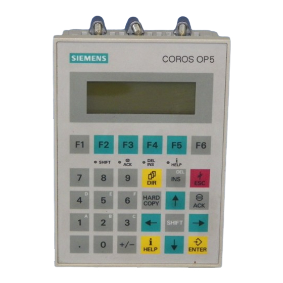
Page 18: Design Of Operator Panel Op5
System keyboard 24 keys with permanently assigned function calls. Interfaces The OP5/A1 has an interface for connecting the PLC/computer and printer. The OP5/A2 has two interfaces for this purpose. Manual OP5, OP15 ( ) J31069-D0840-U001-A2-7618... -
Page 19: Design Of Operator Panel Op15
OP15 versions The OP15 is available in the following versions: OP15/A1, OP15/A2, OP15/A1-VF, OP15/A2-VF, OP15/C1 and OP15/C2. The versions listed above differ in their display and communication options. Figure 1-3 Design of Operator Panel OP15 Manual OP5, OP15 ( ) J31069-D0840-U001-A2-7618... - Page 20 8 keys (F1 to F8) beneath the display, which can be configured with screen- specific functions. System keyboard 24 keys with permanently assigned function calls. Interfaces 3 interfaces for connecting the PLC and a printer or a computer. Manual OP5, OP15 ( ) J31069-D0840-U001-A2-7618...
-
Page 21: Functionality
Functionality Functions of OP5 The table below provides an overview of the functions of Operator Panels and OP15 versions OP5 and OP15 with their different versions. Table 2-1 Functionality of OP5 and OP15 OP15 Display – Technology A, C: A-VF: –... - Page 22 Functionality Table 2-1 Functionality of OP5 and OP15 OP15 Message Acquisition – in buffer with date, time, state Variable Input – Numbers or letters – Symbolic variables Display of Actual Value (numerical and symbolic) Combined Actual Value Display and Variable Input...
- Page 23 Functionality Table 2-1 Functionality of OP5 and OP15 OP15 Changing Languages in Online Mode Communication by means of SIMATIC S5 – AS511 A1, A1-VF, C1 – A1, A1-VF, C1 – SINEC L2-DP A2, A2-VF, C2 SIMATIC S7 – A2, A2-VF, C2 –...
- Page 24 Functionality Manual OP5, OP15 ( ) J31069-D0840-U001-A2-7618...
-
Page 25: Part Ii Basic Functions
Using the OP with Its Standard Functions Part II Basic functions General Operation Screens Password Protection Message Handling Recipes STATUS VAR and FORCE VAR Functions with the OPs System Settings on Standard Screens... - Page 26 Manual OP5, OP15 ( ) J31069-D0840-U001-A2-7618...
-
Page 27: Using The Op With Its Standard Functions
ESC, right back to the start screen should you wish. From here you can return to the message level by pressing the ESC key. You can also return di- rectly to the message level from a screen, depending on the configuration. Manual OP5, OP15 ( ) J31069-D0840-U001-A2-7618... - Page 28 You acknowledge an alarm message by pressing the ACK key. You hide a system message by pressing the ESCAPE key. Once the alarm message has been acknowledged or the system message cleared, the OP returns to the point from which it changed to the message level. Manual OP5, OP15 ( ) J31069-D0840-U001-A2-7618...
-
Page 29: Standard Screens
Furthermore, login and logout are included here. Figure 3-2 shows an overview of the screen hierarchy of standard screens. You will find detailed information on functions and handling standard screens in the relevant chapters of this manual. Manual OP5, OP15 ( ) J31069-D0840-U001-A2-7618... - Page 30 Using the OP with Its Standard Functions Figure 3-2 The Standard Screens Manual OP5, OP15 ( ) J31069-D0840-U001-A2-7618...
-
Page 31: Branching In Standard Screens
Alarms Screens Record StatVAR ForceVAR System Password Figure 3-3 Branching at Screen Level (for an OP15/C having a 8x40 display) Basic screen OP5 Events Alarms >> Figure 3-4 Branching at Screen Level (for OP5) Manual OP5, OP15 ( ) J31069-D0840-U001-A2-7618... - Page 32 Functions are called by means of the soft keys assigned to them during con- figuration. As protection against unauthorized use, a password having a specific pass- word level has to be entered first for some functions (refer to Chapter 6). Manual OP5, OP15 ( ) J31069-D0840-U001-A2-7618...
-
Page 33: General Operation
SHIFT key. The second function of a dual-as- signment key can then be called. On the OP15, the LED is located directly on the key, and on the OP5 it is beneath the function key strip adjacent to the SHIFT symbol. - Page 34 The key is enabled only when the LED is on. With the OP15, the LED is lo- cated on the key; with the OP5, it is located beneath the function key strip, next to the DEL/INS symbol.
- Page 35 Outputs the current display to the printer. HELP key (displays information text). When the assigned LED is on (on the OP15, on the key; on the OP5, beneath the function key strip, next to the HELP symbol), information text relating to the current display can be viewed on the screen (refer to section 4.1.2).
-
Page 36: Escape Functions
To cancel the display of information text, press ESCAPE to return to the pre- information text vious display. Reset while To cancel scrolling through messages at the message level, press ESCAPE to scrolling through reset the display to the current message. messages Manual OP5, OP15 ( ) J31069-D0840-U001-A2-7618... -
Page 37: Information Text
Scrolling through The UP and DOWN keys and are used to scroll through information text, information text if appropriate. The ESCAPE key terminates display of information text, and the previous display is shown again. Manual OP5, OP15 ( ) J31069-D0840-U001-A2-7618... -
Page 38: Entering Values
You can also use the arrow keys to move the cursor to the left or right to the previous input field to insert a different value in it. 6. Close the screen by pressing ESCAPE. Manual OP5, OP15 ( ) J31069-D0840-U001-A2-7618... -
Page 39: Entering Numerical Values
If a numerical field has been configured with a certain number of decimal places and too many have been entered, they are ignored; if too few have been entered, the field is padded with zeroes. Manual OP5, OP15 ( ) J31069-D0840-U001-A2-7618... -
Page 40: Entering Alphanumeric Values
4. Select O and, using the arrow key, move right one position. 5. Select K and, using the arrow key, move right one position. 6. Select T and, using the arrow key, move right one position. Manual OP5, OP15 ( ) J31069-D0840-U001-A2-7618... -
Page 41: Entering Symbolic Values
The list of options with its configured symbolic inputs is activated. 2. Select the value you require using the arrow keys. 3. Enter the value you selected by pressing ENTER. Shift Lock mode is de-activated automatically when you press ENTER. Manual OP5, OP15 ( ) J31069-D0840-U001-A2-7618... - Page 42 General Operation Manual OP5, OP15 4-10 ( ) J31069-D0840-U001-A2-7618...
-
Page 43: Screens
Screens can be grouped during configuration in a screen directory, which is used to display them on screen or print and edit them. A screen can be retrie- ved from its screen directory by its screen number and its screen title, if con- figured. Manual OP5, OP15 ( ) J31069-D0840-U001-A2-7618... -
Page 44: Screen Entries
OP using a selection field and apply to the screen entry. With inputs of numerical values, configured number formats and limit values apply with respect to the number of places before and after the decimal point. Manual OP5, OP15 ( ) J31069-D0840-U001-A2-7618... -
Page 45: Choosing Screens
To implement operator guidance, a screen can be chosen from the PLC by PLC job means of a PLC job. In this instance, the cursor is already positioned in a specified entry or in an input field, in which the operator can perform his input. Manual OP5, OP15 ( ) J31069-D0840-U001-A2-7618... -
Page 46: Editing Screens
2. Scroll with the cursor keys DOWN or UP to the screen number you require or, if configured, to the screen title. 3. Press ENTER to print. 4. Terminate the action – for example, by pressing ESCAPE. Manual OP5, OP15 ( ) J31069-D0840-U001-A2-7618... - Page 47 Synonymous with password level 9 is use of the authorization input. If an operator logs in with the password of a specific password level on the display, he is authorized to execute functions of this and lower levels. Manual OP5, OP15 ( ) J31069-D0840-U001-A2-7618...
- Page 48 Choose the standard screen Password Logout. Upon selection of the standard screen, the OP switches from the current pass- word level to the lowest password level, level 0, and branches to the message level. Manual OP5, OP15 ( ) J31069-D0840-U001-A2-7618...
- Page 49 If you just want to change the password level and not the password, skip the field containing the password entry by pressing ENTER. Then move the cur- sor with the RIGHT arrow key to the field for the password level and enter the new level. Manual OP5, OP15 ( ) J31069-D0840-U001-A2-7618...
-
Page 50: Password Protection
Deleting To delete a password, call the password entry in the same way as you do for passwords allocating and changing a password but overwrite the first character of the password with a zero. Manual OP5, OP15 ( ) J31069-D0840-U001-A2-7618... -
Page 51: Message Handling
OP or maloperations and break- downs in communication. Issued event messages and alarm messages are stored in separate message buffers on the OP. Messages contained in the buffers can be displayed or out- put to a connected printer. Manual OP5, OP15 ( ) J31069-D0840-U001-A2-7618... -
Page 52: Event Messages And Alarm Messages
OP when they arrive. The following details are entered in the buffer in chronological order: times of incidents arrivals and departures of incidents acknowledgements of alarm messages message numbers values of variables at the time of arrival and departure. Manual OP5, OP15 ( ) J31069-D0840-U001-A2-7618... -
Page 53: Acknowledging Alarm Messages
If no more alarm messages are waiting to be displayed, the OP reverts to the operating level from which it branched to the message level to display the alarm messages. Manual OP5, OP15 ( ) J31069-D0840-U001-A2-7618... -
Page 54: Inhibiting Alarm Messages
They are stored in the alarm buffer only from the time they first occur until such time as the display is inhibited. Note The alarm message inhibit function should be used only during the commis- sioning phase of the OP. Manual OP5, OP15 ( ) J31069-D0840-U001-A2-7618... -
Page 55: System Messages
Some minor errors and operator errors are not logged in the system message buffer. Messages from the system message buffer are displayed in the same order as they arrived, i.e. first in first out, last in last out. Manual OP5, OP15 ( ) J31069-D0840-U001-A2-7618... -
Page 56: Displaying Messages
(first) or most recent (last) alarm message when there are several of them waiting. To do this, choose System DispMsg and set the corresponding parameter. Manual OP5, OP15 ( ) J31069-D0840-U001-A2-7618... -
Page 57: Display Sequences
3. Acknowledged alarm message yet to depart; the second line displays simul- taneously the most recent highest-priority event message yet to depart. 4. Standby message. Manual OP5, OP15 ( ) J31069-D0840-U001-A2-7618... -
Page 58: Scrolling Through Waiting Messages At Message Level
Choose the standard screen Alarms Text (to display alarm messages) or Events Text (to display event messages). By using the UP and DOWN arrow keys, you can now scroll through the list of configured message text. Manual OP5, OP15 ( ) J31069-D0840-U001-A2-7618... -
Page 59: Viewing Message Buffers
Viewing total num- To obtain an overview of all the alarm messages and the total number of ber of messages in alarm messages still waiting in the buffer, choose the standard screen event buffer Alarms Number. Manual OP5, OP15 ( ) J31069-D0840-U001-A2-7618... - Page 60 To obtain an overview of all the event messages and the total number of number of event messages still waiting in the buffer, choose the standard screen Events messages in event Number. buffer Manual OP5, OP15 7-10 ( ) J31069-D0840-U001-A2-7618...
- Page 61 Message number of the system message. The displayed message number is number 200. on date time Date and time of occurrence of the system message. Display message text of selected system message: Return to system message list: Manual OP5, OP15 7-11 ( ) J31069-D0840-U001-A2-7618...
-
Page 62: Deleting Messages
Overflow. If the alarm buffer cannot accept any more messages, those which have been acknowledged and have departed are the first to be deleted automati- cally until such time as the configured remaining buffer size is reached. Manual OP5, OP15 7-12 ( ) J31069-D0840-U001-A2-7618... -
Page 63: Automatically Deleting The Event Buffer Upon Buffer Overflow
If the system message buffer is completely full, the oldest message is deleted automatically from the buffer when another system message occurs. There is no overflow warning or forced printout of the deleted message, in the case of event and alarm messages. Manual OP5, OP15 7-13 ( ) J31069-D0840-U001-A2-7618... -
Page 64: Printing Messages
3. Move the cursor on the parameter list to Message Log. 4. By entering a symbolic value, set ON or OFF. 5. Confirm by pressing the ENTER key. 6. Exit from the standard screen by pressing the ESCAPE key. Manual OP5, OP15 7-14 ( ) J31069-D0840-U001-A2-7618... -
Page 65: Printing The Message Buffer
Print to print event messages. The default setting is . The default setting can be modified during configuration. A choice of either online on the OP is possible only when it has been configured. Manual OP5, OP15 7-15 ( ) J31069-D0840-U001-A2-7618... - Page 66 Message Handling Manual OP5, OP15 7-16 ( ) J31069-D0840-U001-A2-7618...
-
Page 67: Recipes
”Mixture”. Mixing station To the bottling TANK TANK TANK station MIXER Example: OP15 PLC (e.g., SIMATIC S7) Figure 8-1 Example of a fruit juice plant Manual OP5, OP15 ( ) J31069-D0840-U001-A2-7618... - Page 68 Data record 3 ”Mixture” All data records are stored on the OP. Only the data record which is active at the moment is stored on the PLC. This saves memory space in the PLC. Manual OP5, OP15 ( ) J31069-D0840-U001-A2-7618...
- Page 69 Recipes are combined into a recipe directory which can be used to indicate recipes them on the display, and to print and edit them. A recipe is located in the recipe directory under its recipe number and its recipe title. Manual OP5, OP15 ( ) J31069-D0840-U001-A2-7618...
- Page 70 The variables of the data record are stored in an intermediate storage location on the PLC (e.g., recipe mailbox on the SIMATIC S5). See User manual Communication for detailed information on the internal procedures. Manual OP5, OP15 ( ) J31069-D0840-U001-A2-7618...
-
Page 71: Setting Up And Editing Data Records
Do not overwrite: Press ESCAPE. 10. Exit standard screen with ESCAPE. As long as you have not confirmed an input value, you can terminate editing with ESCAPE. The old value is then displayed again. Manual OP5, OP15 ( ) J31069-D0840-U001-A2-7618... - Page 72 2. Position cursor in the field for the data record name, enter the name, and confirm. The data record name may not exceed 12 characters. The next time you call the data record directory, you will find the new data record listed under the new data record number. Manual OP5, OP15 ( ) J31069-D0840-U001-A2-7618...
-
Page 73: Copying Data Records
4. Position cursor in the field for the data record name, enter the name, and confirm. The next time you call the data record directory, you will find the new data record in the list. Manual OP5, OP15 ( ) J31069-D0840-U001-A2-7618... -
Page 74: Transferring Data Records
Transfer. It is shown below. No. of the source data record No. of the destination data record Source: Dest.: The recipe/data record active in Juice the PLC Accept Recipe number selected on the PLC: Figure 8-3 Transfer screen Manual OP5, OP15 ( ) J31069-D0840-U001-A2-7618... - Page 75 Symbolic value entries in the input fields source and destination: The data record numbers from data records already stored on the OP can be taken from a data record selection list. ”PLC” stands for data record 0 in the selection list. Manual OP5, OP15 ( ) J31069-D0840-U001-A2-7618...
- Page 76 (see examples), and confirm. 5. Position the cursor on the Accept field, and confirm transfer. During the data transfer, an asterisk (”*”) is indicated in the acceptance field. 6. Exit the standard screen with ESCAPE. Manual OP5, OP15 8-10 ( ) J31069-D0840-U001-A2-7618...
-
Page 77: Deleting Data Records
5. Delete: Press ENTER. Do not delete: Press ESCAPE. 6. Repeat steps 3 and 4 as necessary. If only one single data record exists, this record cannot be deleted. 7. Exit the standard screen with ESCAPE. Manual OP5, OP15 8-11 ( ) J31069-D0840-U001-A2-7618... - Page 78 Recipes Manual OP5, OP15 8-12 ( ) J31069-D0840-U001-A2-7618...
-
Page 79: Status Var And Force Var Functions With The Ops (S7/S5 Only)
DB34 DW122 KM = 00010010 00110100 KT = 3.4 s Value field Format field Numbers field Operand field Updating in progress Figure 9-1 Display of PLC Operands for the SIMATIC S5 (Example: OP15/A, 2x40) Manual OP5, OP15 ( ) J31069-D0840-U001-A2-7618... - Page 80 If the asterisk does not flash, this means that the OP did not succeed in establishing a logical link to the PLC. Inputs cannot be made while updating is in progress. Updating can be can- celed by pressing ESCAPE. Manual OP5, OP15 ( ) J31069-D0840-U001-A2-7618...
- Page 81 0 to FFFF 1ABC KM: bit pattern 0000000000000000 0000000000001001 1111111111111111 Digits are overwrit ten character by character and are left justified KT: time-value 0.0 to 9990 (sec) 012.1 ( coded time base (output only) Manual OP5, OP15 ( ) J31069-D0840-U001-A2-7618...
- Page 82 0110 1100 0100 1111 Timer 0 to FFFF 2A3C 0.0 to 9990 (sec) 014.1 Timer 0 to FFFF 2A3C 0.0 to 9990 (sec) 014.1 16 bits 0110 1100 0100 1111 Only for PPI Only for MPI Manual OP5, OP15 ( ) J31069-D0840-U001-A2-7618...
-
Page 83: System Settings On Standard Screens
2. Select the language you require by means of a symbolic input. The selec- tion list contains only the languages which have been loaded on the OP. 3. The OP performs a cold restart and loads all elements of language-depen- dent text in the new language. Manual OP5, OP15 10-1 ( ) J31069-D0840-U001-A2-7618... -
Page 84: Modifying Parameters In Online Mode
1. Choose the standard screen System DispMsg. 2. Select the corresponding parameter, i.e. either First or Last. 3. Exit from the standard screen – for example, by pressing the ESCAPE key. Manual OP5, OP15 10-2 ( ) J31069-D0840-U001-A2-7618... -
Page 85: Adjusting Contrast
Direct contrast The display contrast of the LCD on the OP5 and OP15 can be adjusted at all adjustment times in normal mode by means of direct control: 1. Press SHIFT. The SHIFT LED lights. -
Page 86: Modes
1. Choose the standard screen System OpMode. 2. Set the mode you require by means of a symbolic input. 3. Terminate the function call. You will find further information on OP modes in Chapter 16 of this manual. Manual OP5, OP15 10-4 ( ) J31069-D0840-U001-A2-7618... -
Page 87: Part Iii Expanded, Configurable Functions
Process-Dependent Operator Guidance Part III Expanded, Configurable Functions Schedulers Controlling the OP from the PLC... - Page 88 Manual OP5, OP15 ( ) J31069-D0840-U001-A2-7618...
-
Page 89: Process-Dependent Operator Guidance
11.1 Branching by Means of Soft Keys and Function Keys Soft keys: You can assign function calls to the function keys on the OP5 and the OP15. function keys with We distinguish in this instance between local and global assignment. Global a variable means that the assignment applies to the entire configuration. -
Page 90: 11.2 Self-Defined Screen Hierarchy
Defining the Another feature that is configured is the picture you want to have displayed start-screen on the OP as your start screen. Manual OP5, OP15 11-2 ( ) J31069-D0840-U001-A2-7618... - Page 91 After they have been filled, the bottles are capped, labeled and transferred to pallets. The configured basic screen could look – for example, on the OP5 display – like the one shown in figure 11-2. It consists of static text only.
- Page 92 – for example, OPEN or CLOSED). Tank2 Contents: 371 liters Temp.: 17.0 C Valve: OPEN >> Figure 11-4 Screen with Input and Output Fields (Example) Manual OP5, OP15 11-4 ( ) J31069-D0840-U001-A2-7618...
-
Page 93: Schedulers
When a scheduler time is reached, the configured bit is set in the interface area of the PLC. See User Guide Communication for detailed information on the interface area of the PLC. Manual OP5, OP15 12-1 ( ) J31069-D0840-U001-A2-7618... - Page 94 The scheduler is now activated. Deactivating You can delete the scheduler time in a screen entry by pressing the DELETE schedulers key. The scheduler is then deactivated (i.e., the configured function will not be executed). Manual OP5, OP15 12-2 ( ) J31069-D0840-U001-A2-7618...
-
Page 95: Controlling The Op From The Plc
For this, you must have created the necessary data area on the PLC for the keyboard image and have specified the appropriate area pointer in the config- uration for assigning the key to a bit. Manual OP5, OP15 13-1 ( ) J31069-D0840-U001-A2-7618... -
Page 96: Release
PLC instead of on the OP. area If the PLC is required to announce that an alarm message has been acknowl- acknowledgment edged, this can be done following creation of a suitable data area. area Manual OP5, OP15 13-2 ( ) J31069-D0840-U001-A2-7618... -
Page 97: Part Iv Commissioning And Description Of Devices
Mechanical Installation Part IV Commissioning and Description of Devices Electrical Installation Commissioning Device Description Connecting a printer Test and Monitoring Functions Maintenance... -
Page 98: Manual Op5, Op15
Manual OP5, OP15 ( ) J31069-D0840-U001-A2-7618... - Page 99 OP fits properly. Installing the OP Insert the OP from the front into the prepared cutout. Attach the OP5 firmly to the front panel from behind with the three screw type hooks enclosed with the device;...
- Page 100 Front panel Rear of OP15 Rear of Figure 14-1 Positions for Screw Type Hooks on the OP5 and OP15 To attach them, you must put in the screw type clamps in the housing of the OP and screw the threaded spindles at the rear with an Allen key towards the front panel (14-2).
- Page 101 PLC in accordance with EMC guidelines and the use of interfer- ence-proof cables. Caution Assemblies may be changed only by suitably qualified persons who must be completely familiar with all the warning notices and steps of this manual. Manual OP5, OP15 15-1 ( ) J31069-D0840-U001-A2-7618...
- Page 102 All grounding connections in the cabinet must have large cable cross sections and be applied over a large surface. Insulate analog devices in the switching cabinet and ground them to a single point in the cabinet using copper tape. Manual OP5, OP15 15-2 ( ) J31069-D0840-U001-A2-7618...
- Page 103 Connect the power supply to the terminal block on the bottom of the housing and wire up the authorization input. Figure 15-1 shows the assignment of the 3-pin terminal block for the OP5/A2, figure 15-2 shows the assignment of the 4-pin terminal block for the OP5/A1 and all OP15 versions. 3-pin terminal block...
- Page 104 4-pin terminal block Input Lock switch, for instance 24 V output Power supply + 24 V Figure 15-2 Assignment of the Terminal Block on the OP5/A1 and OP15 Requirements for Rated voltage + 24 V DC the power supply Voltage range...
- Page 105 (refer to the ST80.1 catalog). V.24 COM1/2 TTY passive (25-pin) TTY/V.24 converter PU 7xx OP15 TTY passive COM1 (25-pin) V.24 COM2 (9-pin) Figure 15-3 Connection Configuration Scheme for a Configuration Computer Manual OP5, OP15 15-5 ( ) J31069-D0840-U001-A2-7618...
- Page 106 RS422 OP 15/A1, IF2B RS422/RS485 A1-VF, C1 RS485 SIMATIC S7 RS485 OP 15/A2, IF2B A2-VF, C2 SINEC L2-DP 1) Any SINEC L2 bus terminal (except FSK) Figure 15-4 Connection Configuration Scheme for PLCs Manual OP5, OP15 15-6 ( ) J31069-D0840-U001-A2-7618...
- Page 107 PLC is in Stop mode, for example. (Life-bit monitoring continues to be performed on the PLC.) System performance may deteriorate due to higher loading of the inter- face to the PLC. Manual OP5, OP15 15-7 ( ) J31069-D0840-U001-A2-7618...
- Page 108 OP and processed (for ex- ample, display of the associated message or the actual value). Not until ”Ap- ply” is pressed a second time is the PU status function activated. Manual OP5, OP15 15-8 ( ) J31069-D0840-U001-A2-7618...
- Page 109 Switch on OP power supply Set Download mode by means of the standard screen System OPMode Download Download configuration data to OP ProTool/ Lite COM1/2 Message level Figure 16-1 Diagram of Commissioning Manual OP5, OP15 16-1 ( ) J31069-D0840-U001-A2-7618...
- Page 110 Download mode on the OP. Before you do so, enter the password for the password level concerned, if required. If this standard screen is not available in your configuration, press – while switching on the power supply – the following three keys Manual OP5, OP15 16-2 ( ) J31069-D0840-U001-A2-7618...
- Page 111 OP. You will find an overview of the most important system messages together with notes on troubleshooting in an appendix to this manual. Manual OP5, OP15 16-3 ( ) J31069-D0840-U001-A2-7618...
- Page 112 If communication is not possible – for example, because the cable to the PLC has not been inserted – the OP displays a system mes- sage. After start-up, the OP is at message level. Message level Manual OP5, OP15 16-4 ( ) J31069-D0840-U001-A2-7618...
- Page 113 6. Check the different items of message text. 7. Test the function keys. End of test If errors occur when you perform tests 2 through 7 above, you must down- load the configuration again. Manual OP5, OP15 16-5 ( ) J31069-D0840-U001-A2-7618...
- Page 114 The OP15 has the built-in ”loop-through mode” function. The loop-through mode facilitates testing with the PLC during commission- ing since there is then no need to keep on plugging the configuration comput- er alternately into the PLC and the OP. Manual OP5, OP15 16-6 ( ) J31069-D0840-U001-A2-7618...
- Page 115 This chapter describes the versions, dimension drawings and connection ele- ments of Operator Panels OP5 and OP15. 17.1 OP5 OP5 versions The OP5 is available in versions A1 and A2. The functionality of the two versions is virtually identical. Manual OP5, OP15 17-1...
- Page 116 Device Description Connection elements (on bottom of device) Figure 17-1 Location of connection elements on OP5/A1 Figure 17-2 Location of connection elements on OP5/A2 Connections SIMATIC TI SIMATIC S5 SIMATIC S7 Other PLCs Printer 500/505 AS511 SINEC RS422 V24/ RS422/...
- Page 117 Device Description 17.2 OP15 OP15 versions The OP15 is available in six versions. The functionality of the different ver- sions is virtually identical. Manual OP5, OP15 17-3 ( ) J31069-D0840-U001-A2-7618...
- Page 118 IF 2B IF 1 – – IF 2B IF 2B IF 2A – IF 2A – IF 1 IF 1: TTY/V24 IF 2A: TTY/V24 IF 2B: For OP15/A1, A1-VF, C1: For OP15/A2, A2-VF, C2: Manual OP5, OP15 17-4 ( ) J31069-D0840-U001-A2-7618...
- Page 119 ”old” labeling strips, if any, from the device and insert the labels you have prepared for your specific system from the rear of the device into the corresponding slits. Figure 17-3 Replacing Labeling Strips on the OP15 Manual OP5, OP15 17-5 ( ) J31069-D0840-U001-A2-7618...
- Page 120 The same type of interface must be used which was configured for the printer interface (i.e., TTY or V.24). Printer operation To permit operation of a printer despite a connected floppy disk station, this can be looped through. Manual OP5, OP15 17-6 ( ) J31069-D0840-U001-A2-7618...
- Page 121 Phoenix connection terminals protected against pole reversal. Grounding terminal Fine-wire fuse DIP switch, factory setting: both OFF. (Do not change this setting.) Figure 17-4 Connection and setting elements on the floppy disk station Manual OP5, OP15 17-7 ( ) J31069-D0840-U001-A2-7618...
- Page 122 Device Description Manual OP5, OP15 17-8 ( ) J31069-D0840-U001-A2-7618...
- Page 123 For other printers, you have to use the cables supplied or specially manufac- tured ones. Note SIEMENS AG accepts no responsibility whatsoever for malfunctions and damage arising from the use of self-made cables or cables from other manufacturers. Print functions...
- Page 124 – for example, underline, italics). The text attributes have to be stored in ProTool/Lite for the different printers under System Printer Settings by using different control characters. Manual OP5, OP15 18-2 ( ) J31069-D0840-U001-A2-7618...
- Page 125 End of test Unless specified to the contrary, the system returns automatically to the menu after every individual test. When you select ”END TEST”, a hardware reset is initiated and a cold start is executed. Manual OP5, OP15 19-1 ( ) J31069-D0840-U001-A2-7618...
- Page 126 = 3.13 to 3.44 V Note If the battery voltage falls below a value of + 2.5 V, which corresponds to (7 to 8)/16 of + 5 V, a warning is issued in normal operation. Manual OP5, OP15 19-2 ( ) J31069-D0840-U001-A2-7618...
- Page 127 OP executes a cold start. SPC TEST A check determines whether the ASIC chip responsible for the SINEC L2-DP and MPI connection is present. If this is not the case, an appropriate error message is issued. Manual OP5, OP15 19-3 ( ) J31069-D0840-U001-A2-7618...
- Page 128 Test and Monitoring Functions Manual OP5, OP15 19-4 ( ) J31069-D0840-U001-A2-7618...
- Page 129 The procedure for changing the backup battery is described below. Backup battery The backup battery of the OP5 and the OP15 insures that, when the power supply is turned off, operating data are retained in the static RAM of the OP and the hardware clock continues to run (OP15 only).
- Page 130 2. Pull off the connector on the battery lead. 3. Insert the new battery in reverse order. Caution Spent lithium batteries should be treated as special waste. Pack them sepa- rately in leakproof plastic bags for disposal. Manual OP5, OP15 20-2 ( ) J31069-D0840-U001-A2-7618...
- Page 131 Short Description of Standard Screens Part V Appendices System Messages Technical Data Interface Assignment ESD Guidelines Siemens Worldwide...
- Page 132 Manual OP5, OP15 ( ) J31069-D0840-U001-A2-7618...
- Page 133 Brief Description of Standard Screens The table below presents an overview of all the standard screens for Operating Panels OP5 and OP15. Apart from a brief comment on functions, mention is made of the requisite password level. The ”Level 1” column lists the screens that you can choose from the basic screen. These screens allow you to make different calls, which are listed under ”Level 2”.
- Page 134 Log in a user by entering a password. Password Logout Log out a user and branches backward to message level. Password Edit Display password list. Allocate and modify passwords and password levels. Delete passwords. Manual OP5, OP15 ( ) J31069-D0840-U001-A2-7618...
- Page 135 Put the OP in Download mode during start-up (refer to section 16.1), download the configuration again and restart the OP and the PLC. c) If the error continues to occur, please contact the nearest Siemens branch office. Report the number of the error that has occurred and any variable that may be included in the message.
- Page 136 Memory submodule defective, Return device for repair with details of error EPROM memory internal hardware error failure failure Flash Memory submodule defective or Repeat download configuration or return de- memory transfer failure vice for repair failure Manual OP5, OP15 ( ) J31069-D0840-U001-A2-7618...
- Page 137 Connection to PLC OK again fol- lowing a fault $ 119 Automatic start of OP (password list is not compulsorily deleted) $ 125 Language changed by standard screen or PLC job $ 131 Mode change $ 133 Mode change Manual OP5, OP15 ( ) J31069-D0840-U001-A2-7618...
- Page 138 Delete buffer or configure smaller remaining buffer space buffer space $ 227 Alarm buffer full; buffer partially deleted and forced printout initiated $ 229 Keyboard connector faulty or loose Return device for repair (hardware fault) Manual OP5, OP15 ( ) J31069-D0840-U001-A2-7618...
- Page 139 $ 323 In a buffer mask, you pressed (message text), though an entry does not exist for the current message. $ 324 The screen number or entry number in your input does not exist Manual OP5, OP15 ( ) J31069-D0840-U001-A2-7618...
- Page 140 (ESCAPE key) $ 409 Lower limit for input ignored Enter a value greater than or equal to Var $ 410 Upper limit for input ignored Enter a value smaller than or equal to Var Manual OP5, OP15 ( ) J31069-D0840-U001-A2-7618...
- Page 141 $ 528 The specified recipe number does not exist. $ 529 The specified file name does not exist. $ 531 Because recipe configuration was changed, DS is no longer compat- ible and cannot be loaded. Manual OP5, OP15 ( ) J31069-D0840-U001-A2-7618...
- Page 142 $ 615 Line to be output is larger than the Check configuration for log reserved print memory or the num- ber of control sequences is too large $ 616 See Internal Errors $ 617 Manual OP5, OP15 ( ) J31069-D0840-U001-A2-7618...
- Page 143 3, 6, 7, Internal errors 8, 11, 13 $ 634 (Message with one variable) Add to configuration and repeat download Screen title or recipe title not configured 0 to 8, Internal errors Manual OP5, OP15 ( ) J31069-D0840-U001-A2-7618...
- Page 144 $ 655 PLC acknowledgment area not Re-configure PLC OP acknowledgment physically in back of alarm mes- areas and repeat download sage bit area (serious error, no startup) Manual OP5, OP15 B-10 ( ) J31069-D0840-U001-A2-7618...
- Page 145 Internal Error (actual value error) $ 703 Internal Error (job faulty) $ 704 Flash memory full Limit configuration $ 705 Internal Error (S5 error) $ 706 Internal Error (unknown message acknowledged) $ 7xx Internal errors Manual OP5, OP15 B-11 ( ) J31069-D0840-U001-A2-7618...
- Page 146 System Messages Manual OP5, OP15 B-12 ( ) J31069-D0840-U001-A2-7618...
-
Page 147: Technical Data
SRAM working 128 KBytes memory EPROM Firmware 512 KBytes Display Type Number of lines 4 (8) Characters per line 20 (40) Character height 5 mm 5 mm 5 mm 8 (4) mm Manual OP5, OP15 ( ) J31069-D0840-U001-A2-7618... - Page 148 Fuse internal Backup battery Type Lithium cell Voltage 3.6 V Capacity 1.5 Ah Subject to change Authorization input Inhibited U < 3.6 V or open input Enabled 15 V < U < 30 V Manual OP5, OP15 ( ) J31069-D0840-U001-A2-7618...
- Page 149 IEC 801-2 class 3 (contact discharge) RF irradiation ENV 50140 class 3 Burst interference IEC 801-4 class 3 Pulse modulation ENV 50204 Interference Emission (EN 50081-1) RFI suppression level In accordance with VDE 0878, EN 55022 Manual OP5, OP15 ( ) J31069-D0840-U001-A2-7618...
- Page 150 Technical Data Manual OP5, OP15 ( ) J31069-D0840-U001-A2-7618...
- Page 151 2 / 3 – – – – – – – – IF2A – – IF2B – – Pin Assignment General V.24 Protective conductor RxD– TxD+ TxD– Protective conductor RxD+ +20 mA +20 mA +5 Volt Manual OP5, OP15 ( ) J31069-D0840-U001-A2-7618...
- Page 152 Interface Assignment RS 422 RS 485 TxD (B) Data B RxD (B) +5 V +5 V TxD (A) Data A TxD (A) L2–DP/MPI/PPI Data B (isolated) GND (isolated) +5 V (isolated) Data A (isolated) Manual OP5, OP15 ( ) J31069-D0840-U001-A2-7618...
- Page 153 De- vices exposed to such overvoltages cannot immediately be detected as defec- tive in the majority of cases, since faulty behavior may occur only after a long period of operation. Manual OP5, OP15 ( ) J31069-D0840-U001-A2-7618...
- Page 154 – the measuring head has been briefly discharged before measurements are made with a potential-free measuring instrument – for example, by touching a bare metal control cabinet. For soldering, you must use only a grounded soldering iron. Manual OP5, OP15 ( ) J31069-D0840-U001-A2-7618...
- Page 155 With assemblies containing fitted batteries, make sure that the conductive covering battery packing does not come into contact with or short-circuit battery connections; connections if necessary, cover battery connections beforehand with insulating tape or insulating material. Manual OP5, OP15 ( ) J31069-D0840-U001-A2-7618...
- Page 156 ESD Guidelines Manual OP5, OP15 ( ) J31069-D0840-U001-A2-7618...
- Page 157 Siemens Worldwide In this appendix In this appendix you will find the following information. The location of Siemens offices in the Federal Republic of Germany All European and non European branches and representatives of Siemens AG Ägypten Australien Siemens Technical Office Siemens Ltd.
- Page 158 Frankfurt a.M. Salvador de Bahia Freiburg Freiburg São Paulo Vitória Hamburg Brunei Heilbronn Brunei Darussalam Karlsruhe Bulgarien Kassel Kempten/Allg. /All Siemens AG, Vertretung in Bulgarien Ki l Kiel Sofia K bl Koblenz Köln Köln Konstanz Konstanz Laatzen Leipzig Lingen Magdeburg Mainz Mannheim Mü...
- Page 159 Ciudad de Guatemala Quito Honduras Elfenbeinküste Representaciones Electroindustriales S de R.L. – Relec- Siemens AG Abidjan Tegucigalpa El Salvador Hong Kong Siemens S.A. Siemens Ltd. San Salvador Hong Kong Finnland Siemens Oy Espoo, Helsinki Manual OP5, OP15 ( ) J31069-D0840-U001-A2-7618...
- Page 160 Trags Electrical Engineering and Air Conditioning Co. Madras Doha New Delhi Kolumbien Secúnderabad Siemens S.A. Indonesien Barranquilla P.T. Siemens Indonesia, P.T. Siemens Dian-Grana Elek- Bogotá trika, Representative Siemens AG Cali Jakarta Medellín Irak Korea Samhiry Bros. Co. Limited Siemens Ltd.
- Page 161 Guadalajara Salzburg León Wien México, D.F. Oman Monterrey Puebla Waleed Associates Muscat Moçambique Pakistan Siemens Liaison Office Siemens Pakistan Engineering Co., Ltd. Maputo Islamabad Namibia Karachi Siemens (Pty.) Ltd. Lahore Windhoek Peshawar Nepal Quetta Amatya Enterprises (Pvt.) Ltd. Paraguay Kathmandu Rieder &...
- Page 162 Electro Technologies Corporation (Pvt.) Ltd. (ETC) Albufeira Harare Coímbra Singapur Lisboa, Amadora Siemens (Pte.) Ltd. Matosinhos Singapore Porto Slowakische Republik Rumänien Siemens AG Siemens birou de consultatii tehnice Bratislava Bucuresti Slowenien Rußland Siemens d. o. o. Siemens AG Ljubljana oder Spanien Mosmatic Siemens S.A. Moskau...
- Page 163 Conatel S.A. Mbabane Montevideo Syrien Venezuela Siemens AG, Branch (A.S.T.E.) Siemens S.A. Damascus Caracas Taiwan Valencia Siemens Ltd., TELEUNION Engineering Ltd. Vereinigte Arabische Emirate oder Electro Mechanical Co. TAI Engineering Co., Ltd. oder Taichung Siemens Resident Engineers Taipei Abu Dhabi Tanzania Scientechnic Tanzania Electrical Services Ltd.
- Page 164 Siemens Worldwide Yemen (Arab. Republik) Zaire Tihama Tractors & Engineering Co., Ltd. SOFAMATEL S.P.R.L. oder Kinshasa Siemens Resident Engineers Sanaa Manual OP5, OP15 ( ) J31069-D0840-U001-A2-7618...
- Page 165 Siemens Worldwide Manual OP5, OP15 ( ) J31069-D0840-U001-A2-7618...
- Page 166 Configuration Definition of system-specific basic settings, messages and screens using COM TEXT configuration software. Departure of a The time at which a message is withdrawn by the Programmable Logic PLC message Manual OP5, OP15 Glossary-1 ( ) J31069-D0840-U001-A2-7618...
- Page 167 Automatic printouts of alarm or event messages that are deleted upon a buff- er overflow. Hardcopy Output of display contents to an attached printer. Information text Additional, configurable information about messages, screens, screen entries and selection fields. Manual OP5, OP15 Glossary-2 ( ) J31069-D0840-U001-A2-7618...
- Page 168 The requisite password level is preset by means of configuration and can range from 1 (the lowest level) to 9 (the highest level). PLC job Initiation of a function by the PLC. Manual OP5, OP15 Glossary-3 ( ) J31069-D0840-U001-A2-7618...
- Page 169 Startup test Check on the status of the central processing unit and memories each time the supply voltage is applied. System message Draws attention to internal conditions on the OP and the PLC. Manual OP5, OP15 Glossary-4 ( ) J31069-D0840-U001-A2-7618...
- Page 170 BATTERY TEST, 19-2 Connection types, 15-6, 17-2, 17-4 Blank, entering, 4-2 Continuous current, 15-4 Branch Contrast, 2-1, 4-2 in standard screens, 3-5 Control functions, 1-3 with soft keys, 11-1 CPU TEST, 19-2 Brightness, 10-3 Manual OP5, OP15 Index-1 ( ) J31069-D0840-U001-A2-7618...
- Page 171 7-13 overflow, A-1 event messages, A-1 print, A-1 system message buffer, 7-13 view, A-1 DELETE key (OP5/OP15), 4-2 Events, 7-3 Departed message, 7-2 Extended character set, 4-8 Design, OP5, OP5/A2, 1-6 External floppy disk station, 17-6 Device description...
- Page 172 Grounding rail, 15-2 KEYBOARD TEST, 19-3 Keys acknowledge key, 4-2 arrow keys, 4-3 Contrast control, 4-2 HARDCOPY key, 4-3 DELETE key (OP5/OP15), 4-2 Hardware setup, interference–proof, 15-2 DIR, 5-3 Hardware test, 19-1 directory key, 4-2 HELP key, 4-3 ENTER key, 4-2...
- Page 173 1-6 scroll (message level), 7-8 interfaces, 1-6 Mode LCD , 1-6 Download, 10-4 soft keys, 1-6 Loop–through, 10-4 system keyboard, 1-6 Offline, 10-4 versions, 1-6 Online, 10-4 Operand list, 9-1 Modes, 10-4 Manual OP5, OP15 Index-4 ( ) J31069-D0840-U001-A2-7618...
- Page 174 Screen, Glossary-4 Printer Screen entries, 5-1, 5-2 attaching a printer, 18-1 Screen hierarchy, 3-1, 11-2 set parameters, A-2 Screen level, 3-1, Glossary-4 settings, 18-1 Screen number, 5-1 Printout, 1-4 evaluate, 13-1 Priorities, display, 7-7 Manual OP5, OP15 Index-5 ( ) J31069-D0840-U001-A2-7618...
- Page 175 Title, screen, 5-1 Suppress, alarm messages, 7-4 Together, 7-15 System keyboard Transfer screen, 8-8 OP15, 1-8 Transients, C-2 OP5, 1-6 TTY/V.24 test, 19-2 System keyboard image, 13-2 System keys, C-2 System message, hide, 4-4 Manual OP5, OP15 Index-6 ( ) J31069-D0840-U001-A2-7618...
- Page 176 Values, entering numerical, 4-7 Voltage monitoring, 19-1 Values, input, numerical, 4-6 Voltage range, 15-4 Valuess, input, alphanumeric, 4-6 Versions OP15, 1-7, 17-3 OP5, 1-6, 17-1 Watchdog, 19-3 Versions of device, 17-3 Weight, C-1 OP15, 17-3 Working memory, C-1 OP5, 17-1...
- Page 177 Index Manual OP5, OP15 Index-8 ( ) J31069-D0840-U001-A2-7618...