
Subscribe to Our Youtube Channel
Related Manuals for Korenix JetNet 3006 Series


Summary of Contents for Korenix JetNet 3006 Series
- Page 1 JetNet 3006 / 3006f Series Industrial 6-port Fast Ethernet Switch User’s Manual Version: 1.0 Date: 28-July, 2010...
- Page 2 Korenix JetNet 3006, JetNet 3006f Industrial 6-port Fast Ethernet Switch User’s Manual Copyright Notice Copyright © 2010 Korenix Technology Co., Ltd. All rights reserved. Reproduction in any form or by any means without permission is prohibited.
- Page 3 Declaration of CE This product has passed the CE certification for environmental specifications. Test conditions for passing included the equipment being operated within an industrial enclosure. In order to protect the product from being damaged by ESD (Electrostatic Discharge) and EMI leakage, we strongly recommend the use of CE-compliant industrial enclosure products.
-
Page 4: Table Of Contents
Content 1. Introduction .............1 1-1. Features ............1 1-2. Packing checklist ..........2 2. Hardware Description ........3 2-1. Dimensions ............3 2-2. Front Panel ............5 2-3. Bottom View ............6 2-4. Wiring the System Power Inputs....... 7 2-5 Connecting the Alarm Relay Output ....8 2-6. -
Page 5: Introduction
In the field site applications, unstable power input always impacts on the reliability of system and causes an interruption of communication. To provide a higher reliability, JetNet 3006 series have a wide range redundant power input - 10~60VDC that meets the NEMA-TS2 requirements for power variation. -
Page 6: Packing Checklist
JetNet 3006/JetNet 3006f includes following items: 1 set of JetNet 3006 or JetNet 3006f with DIN Rail Clip Quick Installation Guide x1 JetNet3006 or JetNet 3006f Quick Installation Guide To get more information about operating instructions, please visit http://www.korenix.com/downloads.htm for user’s manual download. -
Page 7: Hardware Description
2. Hardware Description This session introduces JetNet 3006 and JetNet 3006f enclosure port information, panel design and describes how to install the system with other equipments. 2-1. Dimensions 2-2. Front Panel 2-3. Bottom View 2-4. Wiring System Power Inputs 2-5. Wiring the Alarm Event Relay Output 2-6. - Page 8 JetNet 3006f...
-
Page 9: Front Panel
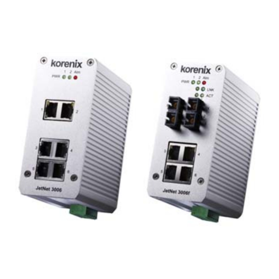
2-2. Front Panel The Front Panel of the JetNet 3006 and JetNet 3006f are shown in Figure A as below. Alarm LED Alarm LED Power LED Power LED Fiber Receive Fiber Transmit Activity LED Activity LED Link LED Figure A. -
Page 10: Bottom View
2-3. Bottom View The bottom side of JetNet 3006 and JetNet 3006f is shown in the below Figure B. It includes one 7-pin DIP switch for system configuration and one 6-pin removable terminal block for the redundant power inputs and event alarm relay output. -
Page 11: Wiring The System Power Inputs
2-4. Wiring System Power Inputs Both JetNet 3006 and JetNet 3006f support 2 power inputs with DC 10~60V wide range redundant power. They also support negative power system for telecom applications. The following diagrams show the wiring architectures of positive and negative power systems. 1. -
Page 12: Connecting The Alarm Relay Output
the device before powering on the systems. 2-5 Connecting the Alarm Relay Output JetNet 3006 and JetNet 3006f support one dry alarm relay output for power and port event to alert administrator. The specification of relay conductor is 24W when it connects with a DC 24V power source. -
Page 13: System Led Indicators
2-6. System LED Indicators The front panel of JetNet 3006 / JetNet 3006f includes 2 Power LEDs, 1 LED for alarm relay active indication and 2 LEDs per each Ethernet port for link and activity indication. The following table describes the functions for each LED indicator. - Page 14 and auto negotiation features that allow users to connect with other devices with straight through or cross-over cabling. It also supports speed auto-negotiation for 10/100Mbps. The following diagram shows the straight through and cross-over cablings. The RJ-45 ports support auto-MDI/MDI-X function without any cable change in case an Ethernet cable is used to connect other devices, such as computers, switches or hubs.
- Page 15 be considered when executing system design. To help you with your system design, the specifications of fiber transceiver are shown in the following table. Fiber Port type Parameter Link Distance: 2KM (Max.) Wave-length: 1310nm Multi-mode 2KM Launch Power: -20dBm ~ -14dBm Receive sensitivity: -31dBm~0dBm Link Budget: 11dBm Link Distance: 30KM (Max.)
-
Page 16: Din Rail Mounting
3. DIN Rail Mounting The DIN Rail clip is screwed on the rear panel of the device which supports EN 50022 type rail installation. The following diagram includes EN50022 rail dimensions for your reference. The DIN rail should be behind the spring when installing the JetNet device onto the standard DIN Rail. -
Page 17: System Configuration
4. System Configuration Both JetNet 3006 and JetNet 3006f support port linked down event and power off event alarm which are configured by the 7-DIP switch. The following table describes the function of each DIP switch: DIP no. Status Description DIP 1~6 Enable the port alert function and trigger the contact of alarm relay output to form a close circuit when a port... -
Page 18: System Installation
5. System Installation Following figure illustrates a typical application of JetNet 3006 and JetNet 3006f: In this application diagram, JetNet 3006 and JetNet 3006f provide graceful anti-electromagnetic interference that ensure the reliable communication not interfered by the noises generated from the motors of facility, railway/subway power systems or Intelligent Traffic Control System. - Page 19 DIN-Rail clip is not attached to the JetNet Switch, check with your supplier to solve the problem. 3. To place the JetNet Switch on the DIN-Rail track, refer to the DIN-Rail Mounting section. 4. Pull the terminal block off the JetNet Switch and wire the power lines. Refer to the Wiring DC Power Inputs section for how to wire the power inputs.
- Page 20 11. To enable the “Command Line mode”, click on Run in the Start menu, type Command, and click on OK to continue. Type ping 192.168.1.1 command to check the connection. Here we use IP address 192.168.1.1 as an example.
- Page 21 12. Repeat step 10 to make sure that the connection of each device linked to the JetNet switch is successfully established. 13. Power on the PC host, activate the Command Line mode, and ping the connected Ethernet device by typing “ping 192.168.1.1 –t” command to see if it will respond.
- Page 22 PWR1 will go out. At that moment, if the ping command is still being replied to, then it proves that the redundant power input function works normally.
-
Page 23: Troubleshooting
6. Troubleshooting Make sure you are using the correct DC power suppliers and that the voltage measured at the power connector is DC10 to 60 V. Do not use power suppliers with DC output over 60V. It may damage devices. Select Ethernet cables with specifications suitable for your applications to set up your systems. -
Page 24: Technical Specifications
6. Technical Specifications Technology Standard IEEE802.3 10Base-T IEEE802.3u 100Base-TX IEEE802.3u 100Base-FX IEEE802.3x flow control System Performance Switch Technology 3.2 Gbps Store and Forwarding Technology Aggregate System 1.49Mega Packet per second / 64 byte packet size Throughput MAC Address 1K MAC Packet Buffer 512 Kbits Transfer Packet Size 148,80pps for Ethernet 10Base-T... - Page 25 Installation DIN-Rail mount or Wall Mount Case IP-30 grade steel metal case Dimension 120 (H) x 55 (W)x 108 (D) (with DIN rail clip), unit: mm Weight 0.87kg with package 0.45kg without package Environmental Operating -25~75℃ (JetNet 3006), -25~70℃ (JetNet 3006f), Temperature 0%~95% Humidity (non-condensing) Wide Temp.
- Page 26 Revision History Edition Date Modifications 23-July,2010 New edition 28-July,2010...
-
Page 27: About Korenix
Less Time At Work! Fewer Budget on applications! The Korenix business idea is to let you spend less time at work and fewer budget on your applications. Do you really want to go through all the troubles but still end up with low quality products and lousy services? Definitely not! This is why you need Korenix.
Need help?
Do you have a question about the JetNet 3006 Series and is the answer not in the manual?
Questions and answers