Advertisement
Quick Links
Download this manual
See also:
Instruction Manual
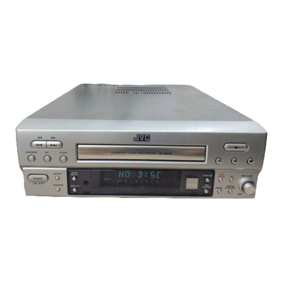
SERVICE MANUAL
COMPACT DISC RECORDER
Contents
Safety precautions ----------------------- 1-2
Disassembly method -------------------- 1-3
Troubleshooting -------------------------- 1-6
Description of major ICs ---------------- 1-11
COPYRIGHT
XL-R910SL
This service manual is printed on 100% recycled paper.
2001 VICTOR COMPANY OF JAPAN, LTD.
XL-R910SL
Area Suffix
J ------------------- U.S.A.
C ---------------- Canada
B --------------------- U.K.
E -- Continental Europe
EN --- Northern Europe
No.A0009
Apr. 2001
Advertisement

Related Manuals for JVC XL-R910SL


Summary of Contents for JVC XL-R910SL
- Page 1 XL-R910SL SERVICE MANUAL COMPACT DISC RECORDER XL-R910SL Area Suffix J ------------------- U.S.A. C ---------------- Canada B --------------------- U.K. E -- Continental Europe EN --- Northern Europe Contents Safety precautions ----------------------- 1-2 Disassembly method -------------------- 1-3 Troubleshooting -------------------------- 1-6 Description of major ICs ---------------- 1-11 This service manual is printed on 100% recycled paper.
- Page 2 XL-R910SL 1. This design of this product contains special hardware and many circuits and components specially for safety purposes. For continued protection, no changes should be made to the original design unless authorized in writing by the manufacturer. Replacement parts must be identical to those used in the original circuits.
- Page 3 XL-R910SL Disassembly method <Main body> Removing the metal cover (See Fig.1) Metal cover 1.Remove the three screws A attaching the metal cover on the back of the body. 2.Remove the four screws B attaching the metal cover on both sides of the body.
- Page 4 XL-R910SL Removing the power button arm (See Fig.6) * Prior to performing the following procedure, RCW2 remove the metal cover and front panel assembly. ACW1 The power button arm is lifted up while holding the power switch(orange color part) and removes.
- Page 5 XL-R910SL Removing the power transformer (See Fig.6~8) * Prior to performing the following procedure, Tie band remove the metal cover. Orange 1.Power button arm is removed from power switch color part 2.Disconnect 9pin wire from connector RCW1 on the main board.
-
Page 6: Troubleshooting
XL-R910SL Troubleshooting Power supply / VFD (FL display) section When trouble is found in the power supply and the FL display. Check voltage Check voltage Check voltage Check voltage pin No13,14,18,46,72 of positive of RC7(6800uF/25V) output of RIC1(7805) input of RIC1(7805) - Page 7 XL-R910SL Analog output (play mode) When trouble is found in the analog signal output. Check voltage Check voltage Check voltage Check voltage pin No2,3 of DAC(NIC1, positive of RC7(6800uF/25v) input of RIC2(78L05) output of RIC2(78L05) AK4324) at main at main PCB : 12V?
-
Page 8: Digital Output
XL-R910SL Digital output When trouble is found in the optical output and coaxial output. Check signal Check signal Check connector to NCW1(17P) (digital) input pin No 1 (digital) input pin No 15 Check mechanism of NIC1(74HCN04) of NCW1(17P) Check for MR14,NC7... - Page 9 XL-R910SL Mechanism operation When trouble is found in the mechanism operating. (rotation,play,tray open/close,lead) Check voltage Check voltage Check for RC7,RD5,RD6,RD7,RD8 pin No 2 of RCW3(6P) positive of RC7(6800uF/ RFU3(2.5A),RCW1,PFU1,PFU2 at main PCB : 8V? 25V) : 12V? Check for RQ3,RZD3,RR3...
- Page 10 XL-R910SL Digital recording (CD-R/CD-RW Disc, Unfinalize condition) When trouble is found in the digital recording (optical recording). Check selecting Selecting optical mode by source key for source at front panel :optical Check signal Check voltage (digital) input pin No11 Check voltage of RIC2(78L05)
- Page 11 XL-R910SL Description of major ICs AK4324(NIC1) : D/A Converter 1. Pin layout DVSS DZFL DVDD DZFR AVDD MCLK VREF AVSS BICK AOUTL+ SDATA AOUTL- LRCK AOUTR+ SMUTE AOUTR- DIF2 DEM0 DIF1 DEM1 DIF0 2. Block diagram DIF0 DIF1 DIF2 DEM0 DEM1...
- Page 12 XL-R910SL AH11-00018B(UIC1):System controller 1.Terminal layout 2.Pin function Pin No. Symbol Description Mechanism reset signal output XRST Non connect 2~10 Connect to ground Micom reset signal input RESET Power supply terminal (+5V) Power supply terminal (+5V) Connect to ground Oscillation input terminal (6MHz)
- Page 13 XL-R910SL VICTOR COMPANY OF JAPAN, LIMITED PERSONAL & MOBILE NETWORK BUSINESS UNIT 1644, Shimotsuruma, Yamato, Kanagawa 242-8514, Japan Printed in Japan No.A0009 200104(O)