Table of Contents
Advertisement
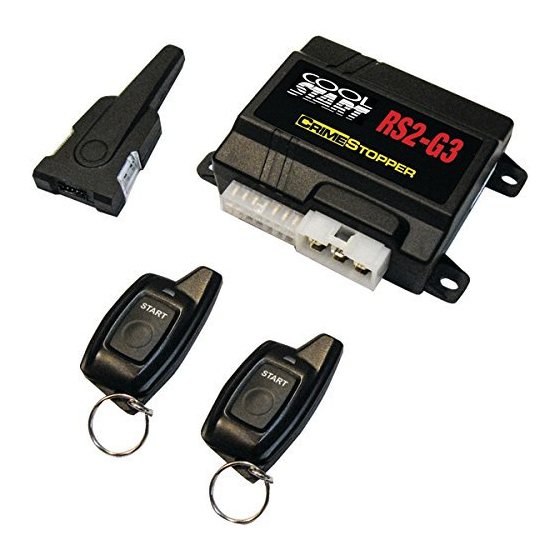
RS2-G3
ONE BUTTON 2-WAY REMOTE START SYSTEM
CONGRATULATIONS on your choice of a "Cool Start" System with Data Port Technology for direct connection to
bypass module by Crime stopper Security Products Inc. This booklet contains the information necessary for
installing your remote starter system. If any questions arise, contact your installation dealer or Crime stopper
Security Products Inc. at the Tech Support number below.
DISCLAIMER:
This installation book is designed for the installer or individual with an existing understanding of automotive electrical
systems, along with the ability to test and connect wires for proper operation. To ease installation, we suggest that
you READ THIS MANUAL before beginning your installation. This book is provided as a GENERAL GUIDELINE
and the information contained herein may differ from your vehicle. Crime stopper Security Products, Inc. and its'
vendors shall not be liable for any accident resulting from the use of this product. This system is designed to be
professionally installed into a vehicle in which all systems and associated components are in perfect working
condition.
TECHNICAL SUPPORT: (800) 998-6880
Monday - Friday 8:00am - 4:30pm Pacific Std. Time
Web Site: www.crimestopper.com
CRIMESTOPPER SECURITY PRODUCTS, INC.
1770 S. TAPO STREET, SIMI VALLEY, CA. 93063
REV 07-25-2014
INSTALLATION INSTRUCTIONS
This device complies with FCC Rules part 15. Operation is subject
to the following two conditions:
harmful interference, and (2) This device must accept any
interference that may be received, including interference that may
cause undesired operation. The manufacturer is not responsible for
any radio or TV interference caused by unauthorized modifications
to this equipment. Such modification could void the user's authority
to use the equipment.
(1) This device may not cause
Advertisement
Table of Contents

Subscribe to Our Youtube Channel
Related Manuals for CrimeStopper RS2-G3


Summary of Contents for CrimeStopper RS2-G3
- Page 1 (2) This device must accept any interference that may be received, including interference that may CRIMESTOPPER SECURITY PRODUCTS, INC. cause undesired operation. The manufacturer is not responsible for any radio or TV interference caused by unauthorized modifications 1770 S.
-
Page 2: Table Of Contents
TABLE OF CONTENTS Pre-Installation Considerations….………...……...……………………………………………………………..….………..3 Installation Cautions & Warnings………………………………………………………………………………..…..……..3 Low Current Wiring……..…………………………………………………………………………………………….……...3-8 Parking Lights…………………………………………………………………………………………………………………...6 Power Door Lock Wiring...…………………………………….…………….……..…………...….……………….……..9-.10 Smart Tachless and Tach Finder Mode………………………………….…………………..…..…….…......11 Tach Programming……..…..…….……………………………………………………………………………….….………..12 Diesel Glow Plug Delay ..………………….……………………………...……………………...…..…………….….….….13 Option Programming Table………. …….………….……………………………..……………..………………..….14-15 Option Descriptions……………..……………………………...………….……….……..………………….……………16-20 Antenna Diagram…………………..….……………….…………………………………………………………..…..………21 Wiring Diagram………………………..….………………………...…………………….….……..…………………….……22 High Current Connector Wiring……………………………………………………………………………………………….23 Remote Star Diagnostics………………………………………………………………………………………………………23 Data Port………..……………………….…………………………………………………………..………………….………24... -
Page 3: Pre-Installation Considerations
INSTALLATION CAUTIONS & WARNINGS DO NOT extend the Remote start ignition harness length. Mount the module so that main harness reaches all ignition switch wiring. Extending these wires could result in poor or improper performance. DO NOT route any wiring that may become entangled with brake, gas pedals, steering column or any other moving parts in the vehicle. - Page 4 WIRING Low Current 14 Pin Plug YELLOW/BLACK OUTPUT: Ground Out when Running (Relay and/or Module not included) ANTI-GRIND RELAY: (Relay not included) The Brown 22 gauge wire can be programmed for Ground When Running (see next page) IGN 1 IGN 2 ENGINE START IGNITION...
- Page 5 WIRING Low Current 14 Pin Plug BROWN: (-) Dome Light Illumination or (-) Ground When Running (Option 13) This is a programmable output that can be programmed 2 ways: 1. 30 Second dome light with unlock = Default. The dome light turns off with ignition on or remote lock. 2.
-
Page 6: Parking Lights
WIRING Low Current 14 Pin Plug WHITE: PARKING LIGHT OUTPUT RED/BLACK: INPUT SOURCE (12 Volts or Ground) The Parking Light circuit can be connected up as a high current positive or negative trigger. Connect to vehicle parking light circuit at the back of light switch or if this is not possible, connect directly to one of the parking lights at the front of the vehicle. - Page 7 WIRING Low Current 14 Pin Plug GRAY: (-) NEGATIVE HOOD PIN SWITCH Connect the gray wire to a switch that is at ground when the hood is open. If an existing switch is not available, then we recommend one to be installed. When this wire is grounded, the remote start is inhibited. The unit will not attempt to start if hood is open.
- Page 8 WIRING Low Current 14 Pin Plug ORANGE / BLACK: (-) OEM DISARM OUTPUT This wire provides a Ground pulse to disarm the vehicles' Factory anti-theft system prior to a Remote Start. Connect this wire to the vehicles' anti-theft disarm wire. This wire is sometimes found coming off the Driver's door key switch or at the Factory Anti-theft control module.
-
Page 9: Power Door Lock Wiring
POWER DOOR LOCK WIRING CONNECTOR BLUE: (-) Negative pulse for UNLOCK Crimestopper Door Lock Accessories: RED: 12V When using external relays (TERM 86) CS-6600DLM: Dual-relay plug-in module for Reverse GREEN: (-) Negative pulse for LOCK Polarity, Positive, or Aftermarket Motors. - Page 10 BASIC DOOR LOCK DIAGRAMS NEGATIVE TRIGGER DOORLOCK WIRING POSITIVE TRIGGER DOORLOCK WIRING GREEN GREEN FUSED +12V BLUE BLUE FACTORY FACTORY POWER POWER LOCKING LOCKING RELAYS RELAYS REVERSE POLARITY DOOR LOCK WIRING AFTERMARKET MOTOR/DOOR LOCK WIRING GREEN GREEN FUSED FUSED +12V +12V BLUE BLUE...
-
Page 11: Smart Tachless And Tach Finder Mode
“SMART TACHLESS” MODE Your CoolStart system includes a unique voltage monitor called “Smart Tachless” mode. This mode allows this unit to efficiently start an engine without the use of a tach signal wire. These modules actively monitor the voltage level of the vehicle to control the starter motor each time a remote start is requested. -
Page 12: Tach Programming
TACH PROGRAMMING & TACH SIGNALS INTRODUCTION This system has 3 methods of monitoring the engine running. Option #1 controls how the system monitors the engine running. 1. Tachless Low Level Mode - Default. When vehicle is remote started, the battery voltage rate will go up because the Alternator starts working. -
Page 13: Diesel Glow Plug Delay
DIESEL GLOW PLUG DELAY There are 2 methods of setting up a Glop Plug delay for Diesel vehicles. 1. Connecting the Pink wire directly to the wait to start lamp on vehicle. Option 23-3 must be selected for Pink wire = Glow Plug. Also, Option 20-4 must be selected for 20 seconds maximum wait time (default = 4 sec.). With this option selected, the starter will crank when the Wait-to-Start light turns off. -
Page 14: Option Programming Table
OPTION PROGRAMMING To Engage Option Programming: 1. Turn Ignition On (must be off at least 5 seconds before turning on). 2. Within 8 seconds, press valet switch 5 times. Wait for the unit to flash the parking lights and/or horn honks 5 times to confirm entering Option Mode. - Page 15 Remote Start Run Time 30 minutes 5 minutes 20 minutes 10 minutes Lock after Remote Lock after Remote Start Lock after Lock & Arm OEM Start & Lock/Arm (to rearm OEM alarm Remote Start Alarm after Abort OEM Alarm after system) only only...
-
Page 16: Option Descriptions
OPTION DESCRIPTIONS 1. Engine Monitoring: This option controls how the system monitors the engine running. You can program for Tachless mode that monitors battery voltage, Tach mode in which the unit uses a Tach signal (RPM) or for Timed Crank as an alternative. There are 4 choices for this option: 1. - Page 17 OPTION DESCRIPTIONS 4. PINK / WHITE WIRE SELECTION: This option controls the Pink / White wire function. 1. Pink / White = Ignition – Default. 2. Pink / White = Accessory 3. Pink / White = Start 5. DATA PORT PROTOCOL: Default = FORTIN This option controls the Data Port Protocol for ADS / FORTIN Series modules or D2D Series modules.
- Page 18 OPTION DESCRIPTIONS 10. BLUE/ORANGE WIRE SELECTION: This option controls the Blue/orange wire function. 1. Blue/orange = Start – Default 2. Blue/orange = Ignition 3. Blue/orange = Accessory 11. ORANGE/WHITE WIRE SELECTION: This option controls the Orange/white wire function. 1. Orange/white = Accessory – Default 2.
- Page 19 OPTION DESCRIPTIONS 15. HORN CHIRP Confirmation with LOCK or UNLOCK This option allows the system to chirp the vehicle horn for Lock and Unlock confirmation. The horn output must be connected to use this feature. Default = OFF. Lock = 1 Chirp Unlock = 2 Chirps 16.
- Page 20 OPTION DESCRIPTIONS 21. TURBO TIMER: The optional Turbo Timer mode allows the Cool Start system to keep a Turbo or Turbo Diesel vehicle running for 1, 3 or 5 minutes [selectively] after you remove the key and exit the vehicle. This is handy for turbo cool-down without the need for expensive turbo timers.
-
Page 21: Antenna Diagram
CONNECTOR PLUG DIAGRAM ANTENNA MODULE: For optimum range and performance, the antenna should be located high up on the front windshield glass. For example: behind the rearview mirror. Note: Window tints or Films may decrease the range of the system. The mounting surface for the antenna should be clean and dry. ANTENNA LOCATIONS WINDSHIELD... -
Page 22: Wiring Diagram
WIRING DIAGRAM... -
Page 23: High Current Connector Wiring
HIGH CURRENT 6-PIN HIGH-CURRENT CONNECTOR (2) RED: 12V POWER INPUT WIRES (30A Fused): Connect to both of these leads to 12V Constant Power. We recommend the BATTERY POSITIVE TERMINAL. BROWN: 12V STARTER OUTPUT 30A: Connect to circuit in the vehicle that has power ONLY while the STARTER MOTOR is CRANKING. GRAY: 12V MULTIFUNCTION OUTPUT 20A (Option 6): This is an optional multi-function output wire the can be configured as a Second IGN, ACC or STARTER output. -
Page 24: Data Port
Databus modules are used to communicate with the vehicles computer at the OBD2 Data connector or Canbus wires. This reduces installation error. Crimestopper Systems with DP Series have a direct Data Port Plug-In for the Databus bypass module. This eliminates conventional wiring between the Alarm/Remote Starter and the bypass interface module. -
Page 25: Pc Programming Menu
PC PROGRAMMING MENU... -
Page 26: Specifications
SPECIFICATIONS LECTRICAL DC Supply voltage DC Tolerance voltage 9V~16V Current (With RF) <25mA Current (Without RF) <10mA –RX01FM PARAMETERS Frequency 433MHz Work current <20mA T34AM-1 WAY PARAMETERS Battery voltage 2*3V Battery life 6 months Static current <3uA Work current <15mA T34FM-2 WAY PARAMETERS Battery voltage... - Page 28 Phone (800) 998-6880 FAX (805) 581-9500 © 2014 Crimestopper Security Products...
Need help?
Do you have a question about the RS2-G3 and is the answer not in the manual?
Questions and answers