Advertisement
Quick Links
Advertisement

Related Manuals for Akai QX-3700


Summary of Contents for Akai QX-3700
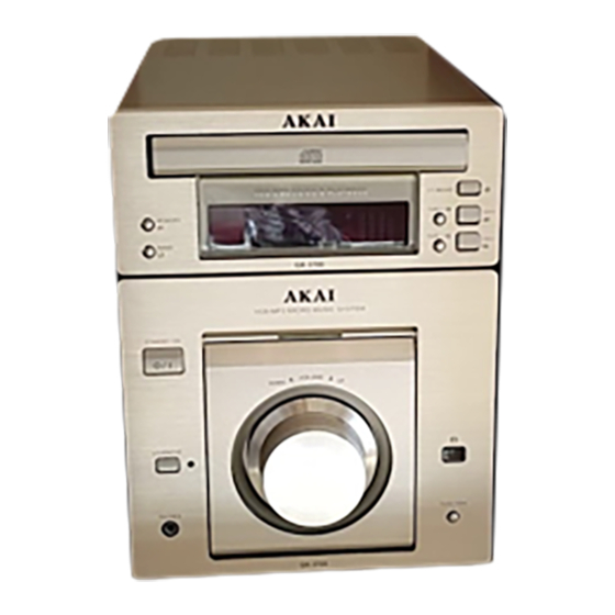
- Page 1 MINI HIFI MICRO COMPONENT SYSTEM Model: QX3700 SERVICE MANUAL www.akai.ru...
- Page 2 SERVICE MANUAL Mini Hi-Fi Micro Component System Hi-Fi MICRO COMPONENT SYSTEM VOLUME STANDBY/ON DOWN/L UP/R REMOTE LOUDNESS PHONES FUNCTION QX-3700 QX-3700 QX-3700 QX-3700 QX-3700...
-
Page 3: Table Of Contents
Contents I. Safety instructions......................... 2 II. Specifications ........................3 III. Level List of Equipments & Instruments Required for Production .......... 6 IV. Block diagram ........................7 V. Wiring diagram ........................8 VI. Schematic Diagram ......................9 VII. Component Diagrams ..................... 10 VIII. -
Page 4: Safety Instructions
I. Safety instructions When using electric products, basic precautions should always 19. Overloading – Do not overload wall outlets and extension be followed, including the following: cords as this can result in a risk of fire or electric shock. 1. Read Instructions – All the safety and operating instructions 20. -
Page 5: Specifications
II. Specifications CONDITIONS OF SPECIFICATION MEASUREMENTS 1. STANDARDS ENVIRONMENTAL CONDITIONS TEMPERATURE : 23°C HUMIDITY : 65% IF NO DOUBT ARISES IN THE JUDEMENT, THE MEASUREMENT CAN BE MADE UNDER CONDITIONS OF TEMPERATURE 10 TO 35°C AND HUMIDITY 45 TO 85%. 2. - Page 6 2. MW Section i. MW Measurement Condition (a) Antenna Input : Loop Antenna (b) Measurement Frequency : Lower Center Upper All versoin 603kHz 1008kHz 1404kHz (In case of no comment, measure at center frequency.) (c) Modulation Frequency : In case of no comment, use 1kHz 30% modulation (e) Selectivity : Arithmetical mean of 2 values at ±10kHz deviated frequency (f) Measurement Point...
- Page 7 4. AMPLIFIER Section i. AMPLIFIER Measurement Condition (a) Power Output Measure without pre-heating (b) Source Impedance Normally 600 (c) S/N Measure the noise level without low frequency ( 80Hz) vibration (d) Frequency Response Measure at -10dBs output (1kHz) by adjusting oscillator output (e) Difference of L/R ch The output level difference between L ch and R ch at ±...
-
Page 8: Level List Of Equipments & Instruments Required For Production
Measurement Specifications Measurement Condition/Method/Remarks Measurement Description Test Input Input Signal Output Vol. Method/Remarks Point Selector Freq. Level Level Frequency - 5.0 dB ± 3.0dB 10Hz Adjust 0dBs Measure the level Response - 4.0 dB ± 3.0dB difference from 1kHz 100kHz output Super Bass + 10dB ±... -
Page 9: Block Diagram
IV. Block diagram LINE1 OUT LINE2 OUT MASTER SYSTEM CONNECTION SYSTEM CONNECTION 25100-3A08 MENU JRC4558A STAN LM1876A MUTE JRC4558B LM1876B STAN FUCTION LEVEL STAND PT16311 DATA 78E54 LOUD MENU 7805 -21V AC3V5 TO CPU AC3V5 7812 +22V +12V AC17V AC17V -22V 2N5401 AC10V... -
Page 10: Wiring Diagram
V. Wiring diagram - 8 -... -
Page 11: Schematic Diagram
VI. Schematic Diagram VFD600 VIDEO OUT AUDIO OUT 25100-3A08 W502 DGND N601 R714 24C02 K601 KS12 IN4148 89C58 TO VCD MPEG R711 KS11 N500 DGND 100P KS10 K600 REMO VD600 C715 IN4148 K603 K604 K605 VD601 PT16311 LED5 R713 N600 IN4148 W503 P503... -
Page 12: Component Diagrams
VII. Component Diagrams i. AMP PCB Component Diagram - 10 -... - Page 13 ii. AMP CONTROL PCB Component Diagram - 11 -...
- Page 14 iii. AMP OUTPUT PCB Component Diagram - 12 -...
- Page 15 iv. CONNECTIVE PCB Component Diagram - 13 -...
- Page 16 v. CPU CONTROL PCB Component Diagram - 14 -...
- Page 17 vi. VCD CONTROL PCB Component Diagram - 15 -...
- Page 18 vii. AUDIO/VIDEO OUTPUT PCB Component Diagram - 16 -...
- Page 19 viii. REMOTE HANDSET PCB Component Diagram - 17 -...
-
Page 20: Exploded Diagram View And Parts List
VIII. Exploded Diagram View and Parts List A. VCD exploded - 18 -... - Page 21 Parts list for VCD exploded view diagram Location Part No. Discription 405-AA0902-05 PANEL FRONT 263-AA0901-06L FRONT LENS 370-AA0801-01 FOOT CSH 227-AA0921-06S MTB CV CD 260-AA0901-01L LENS REAR E7801-013006 FRONT CONTROL PCB ASSY 224-AA0902-01B HOLD PCB 403-AA0903-01 CHASSIS BOTTOM 370-AA0802-01 FOOT CSH REAR 322-AA0801-01 SPOG SPR E7801-013007...
- Page 22 B. AMP exploded - 20 -...
- Page 23 Parts list for AMP exploded view diagram Location Part No. Discription 739-AA0802-04 ASY+VOL 405-AA0803-04 PNL FR B 405-AA0802-06 PNL FR A 289-AA0803-03L RNG+VOL 227-AA0811-05S BRACKET FOR COVER 269-AA0802-01K L+AA 1 269-AA0803-01K L+AA 2 E7801-013002 AMP CONTROL PCB E7801-013001 AMP PCB E7801-013003 AMP OUTPUT PCB 429-AA0801-1...
- Page 24 C. Remote handset Location Part No. Discription 384-010101-11H REMOTE OVERLAY 201-010111-22S REMOTE CAB TOP 373-010101-03Y REMOTE CONTATIVE RUBBER 090-385610-03 P.C.B. REMOTE BOARD 473-010101-01 BATT CONTACT SPRING SHEET-VE 472-010101-01 BATT CONTACT PLATE+VE 203-010131-03S REMOTE CABINET BOTTOM 611-260206-10 SELF-TAPPING SCREW K/T 2.6x6mm 474-010101-01 BATT CONTACT SPRING WIRE 210-010101-03S...
- Page 25 R214 RESISTOR CARBON 180 1/4W ±5% D. Elec. Parts list R215 R216 i. RESISTOR R217 R218 Location Description R208 RESISTOR CARBON 220 1/4W ±5% RESISTOR CARBON 18 1/16W ±5% R201 RESISTOR CARBON 560 1/4W ±5% R110 RESISTOR CARBON 100 1/16W ±5% R203 R112 R200...
- Page 26 C206 iii. DIODE.TRANSISTOR C301 C302 Location Description C409 VD111 DIODE IN4148 C506 VD206 C507 VD207 C508 VD403 C710 VD500 C711 VD600 C716 VD601 C721 VD602 C722 VD603 C723 VD110 DIODE IN4001 C724 VD300 C100 CAPACITOR ELEC 4.7uF/16V ±20% VD100 DIODE IN4007 C101 VD101 C400...
- Page 27 v. OTHERS Location Description RP200 ENCODER VOLUME 1PCS L700 INDUCTANCE 1.8UH 1PCS L300 COIL INDUCTANCE 3UH 1PCS L301 COIL INDUCTANCE 1UH 2PCS L302 X500 CRYSTAL 12MHZ 1PCS IR200 REMOTE SENSOR 1838 1PCS VFD600 VFD 25100-3A08 1PCS XS700 RCA SOCKET AV6-8.4-7 1PCS XS300 JACK SPK WP4-15...
- Page 28 (Attachment 1)
Need help?
Do you have a question about the QX-3700 and is the answer not in the manual?
Questions and answers