Table of Contents
Advertisement
Quick Links
Advertisement
Table of Contents

Subscribe to Our Youtube Channel
Related Manuals for ClimateMaster iGate Connect


Summary of Contents for ClimateMaster iGate Connect
- Page 1 ™ iGate Connect Thermostat Installation Manual...
-
Page 2: Table Of Contents
CONTENTS GETTING STARTED Welcome Technical Support Before You Begin HVAC System Compatibility Information Approvals FCC Compliance Statement Specifi cations Wiring Requirements ™ INSTALLING THE iGate Connect THERMOSTAT Step 1. Power Off HVAC Equipment Step 2. Remove Existing Thermostat ™ Step 3. Install the iGate Connect Thermostat Step 4. - Page 3 NAVIGATING THE MENUS ™ CONFIGURING THE IGATE CONNECT THERMOSTAT Thermostat Confi g Equipment Thresholds Humidity Control Settings Service Mode Sensors Reset HVAC Equipment Settings Performing a Hardware Reset ™ Rebooting the iGate Connect Thermostat Confi guring Reminders and Alerts Alerts END USER SOFTWARE LICENSE AGREEMENT...
- Page 4 This Page Intentionally Left Blank...
-
Page 5: Getting Started
This step–by–step Installation Manual will walk you through all aspects of the installation. To ensure an on–going service relationship with your customers, please register all of your ClimateMaster thermostats in your Contractor Portal. Technical Support Our technical support team is available to answer... -
Page 6: Before You Begin
Before You Begin This product is intended to be installed by trained service professionals. This manual explains the procedures for ™ installing the ClimateMaster iGate Connect thermostat. Please read it carefully before beginning the installation. For information on how to operate the ™... -
Page 7: Hvac System Compatibility Information
HVAC System Compatibility Information ™ The iGate Connect thermostat is designed ® to operate with the ClimateMaster Trilogy Geothermal Unit. ™ The ClimateMaster iGate Connect thermostat supports the following equipment: Equipment Supported? ® Trilogy with Auxiliary Heat ™ iGate Smart Tank... -
Page 8: Approvals
Approvals This product was designed and built in accordance to RoHS directive 2002/95/EC and contains no hazardous substances as defi ned by this directive. FCC Compliance Statement This equipment has been tested and found to comply with the limits for Class B digital devices, pursuant to Part 15 of the FCC Rules. - Page 9 1. This device may not cause harmful interference. 2. This device must accept any interference received, including interference that may cause undesired operation. Change or modifi cations that are not expressly approved by the manufacturer could void the user’s authority to operate the equipment.
- Page 10 Homologations Ce produit a été conçu et fabriqué conformément à la directive européenne RoHS 2002/95/EC, et ne contient aucune substance dangereuse selon la défi nition de cette directive. Commission fédérale des communications (FCC) Avis de conformité : Le matériel a été testé et jugé conforme aux limitations de la catégorie B des appareils numériques, en vertu de l’article 15 des règles de la FCC.
- Page 11 émetteur. MODEL: AWC99B51 FCC ID: WR9EBSTATSI01 IC: 7981A-EBSTATSI01 CONTAINS FCC ID: DI2CT-EM2606 IC: 1700C-CTEM2606 Warning: Changes or modifi cations not expressly approved by ClimateMaster inc. could void the users authority to operate the equipment.
-
Page 12: Specifi Cations
Specifi cations Temperature ranges Heat: 55 to 80 °F (12 to 27 °C) Cool: 65 to 95 °F (18 to 35 °C) Display: 40 to 100 °F (5 to 37 °C) Sensitivity: +/– 1 °F (0.5 °C) Operating: 32 to 130 °F (0 to 55 °C) Humidity Range Display: 20 to 90% R.H. -
Page 13: Installing The Igate
™ INSTALLING THE IGATE CONNECT THERMOSTAT ™ There are 5 steps to install the ClimateMaster iGate Connect thermostat: Step 1. Power Off Trilogy® Unit Step 2. Remove Any Existing Thermostat ™ Step 3. Install the iGate Connect Thermostat Step 4. Connect the Wiring Step 5. - Page 14 In direct sunlight On exterior, non–insulated or poorly insulated walls In the kitchen or other areas of potentially high heat and/or humidity In an area that could restrict air fl ow To install the thermostat: 1. Gently separate the backplate from the thermostat. 2.
-
Page 15: Step 4. Connect The Wiring
Step 4. Connect the Wiring You need to use low–voltage cable to connect the thermostat to the Trilogy® Unit. To connect the thermostat to the unit: 1. Connect the wires as shown in the wiring diagram. ™ 2. Attach the iGate Connect thermostat to the backplate. -
Page 16: Navigating The Menus
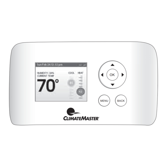
® Step 5. Power On Trilogy Unit After you’ve completed the wiring, you can ™ apply power to the unit. The iGate Connect thermostat receives power from the equipment and will automatically power on. NAVIGATING THE MENUS ™ The iGate Connect thermostat has an easy–to–read color screen that displays all the information you need to confi gure the... - Page 17 (right) On the Home screen, if Auto mode ▶ is enabled, press ▶ to switch between heat and cool set points. For menus, press ▶ to choose the currently highlighted option. On a menu screen, press to choose the currently highlighted option. If a confi guration option is selected, pressing will keep its new value and return back to the previous screen.
-
Page 18: Connect Thermostat
™ CONFIGURING THE IGATE CONNECT THERMOSTAT ™ The fi rst step after installing the iGate Connect thermostat is to confi gure the settings for the equipment being connected. An access code is required to enter the Installation Settings menu. The access code is ™... - Page 19 during low capacity operation. Range will depend on model and minimum heating capacity selection. Max Heating Airfl ow Confi gures the unit airfl ow while operating at maximum capacity in the heating mode. The installer may wish to select a lower cfm than the nominal cfm for this setting to avoid air velocity noise from the ductwork during maximum capacity operation.
- Page 20 from the ductwork during maximum capacity operation. Range will depend on model and maximum cooling capacity selection. Low Dehum Airfl ow Confi gures the unit airfl ow while operating at minimum capacity in the dehumidifi cation mode. Range will depend on model and minimum cooling capacity selection.
- Page 21 Heat Pump Size Select the unit model (0930 or 1860). Blower Type Select the blower type (None or ECM Blower). Loop Confi g Selects the type of internal fl ow device. None, VS Pump – variable speed internal pump, or MOD Valve – internal modulating water control valve.
-
Page 22: Thresholds
HW Pump Confi g (If Applicable) Water Heating Delta T Sets the potable water fl ow rate for the water heating mode. The variable speed potable water pump will adjust the potable water fl ow to maintain the selected temperature diff erence between the entering and leaving potable water during the water heating mode. - Page 23 EXM Settings – Cooling–HW Cut Out Determines the point at which the space cooling demand outpaces the ability of the potable water heating mode to accept the heat of rejection from the cooling mode, when both are active at the same time. At this setting and above the heat of rejection from the cooling mode will be sent to the source (ground loop).
- Page 24 temperature drops more than this amount, the potable water heating mode will be terminated and the space heating mode will be activated. Valid range: 0.5°F to 1.5°F. Default is 1.0°F. – Aux Heat DeadBand Confi gures the amount of space temperature droop allowed from the heating setpoint at maximum unit capacity before allowing auxiliary heat for space heating.
-
Page 25: Humidity Control Settings
Humidity Control Settings To confi gure the humidity control Confi gures humidity control settings (dehumidi- ™ settings on the iGate fi cation/humidifi cation). Connect thermostat: From the Home screen, Humidity Mode press MENU. Select Settings ▶ Determines active humidity mode(s). Valid Installation. - Page 26 speed or valve position (if applicable) to aid in troubleshooting. – Operating Mode Selects the manual mode of operation. Valid selections are: Standby, Const Fan, Cooling, Heating, Aux Heat, EM Heat, Hot Water, and Cooling/HW. – ECM Target Airfl ow Confi gures the target air fl ow during manual operation.
- Page 27 Compressor Speed – displays the current compressor speed in revolutions per second. Comp Current – displays the current compressor amperage. Inverter Current – displays the amperage draw of the inverter. Comp Input Power – displays the power consumption of the compressor in watts. Comp DC Voltage –...
- Page 28 DHW Pump Power – displays the power con- sumption of the DHW pump in watts. DHW Flow – displays the DHW gpm fl ow rate. Hot Water EWT – displays the temperature of the potable hot water entering the potable hot water heat exchanger.
- Page 29 the refrigerant liquid line between the air coil and the electronic expansion valve. Air Coil Vapor – displays the temperature of the refrigerant vapor line between the heat/cool reversing valve and the air coil. HW Coil Liquid – displays the temperature of the refrigerant liquid line leaving the potable water heat exchanger.
- Page 30 for cooling mode, N/A for water heating mode). AUX1 Switch – not used. AUX2 Switch – not used. SD Switch – not used. T1 Temp – not used. T2 Temp – not used. – DIP Switch Settings Allows the service technician to view the status of all dipswitch settings for the connected communicating controls at the thermostat.
-
Page 31: Sensors
AWS Tank – WXM Controller (If Applicable) Model Displays the unit model number Serial Number Displays the storage tank serial number Diagnostics To confi gure the sensors ™ on the iGate Connect – Upper Tank Temp – displays the temperature thermostat: of the DHW at the upper element of the storage tank. - Page 32 Sensor (this temperature is used to control the unit), Monitoring Sensor (this will display the sensor temperature at the thermostat), or Outdoor Sensor (this will display the sensor temperature as the outdoor temperature at the thermostat). – RS–2(sensor name) This is sensor number 1. It will not display a name until a name has been entered.
-
Page 33: Connect Thermostat
Reset HVAC Equipment Settings ™ To reset the iGate You can quickly restore all HVAC equipment Connect thermostat: ™ settings on the iGate Connect thermostat back From the Home screen, to their factory defaults. Any user setting (not press MENU. related to the equipment installed) will remain Select Settings... -
Page 34: Confi Guring Reminders And Alerts
Confi guring Reminders and To confi gure Reminders Alerts and Alerts The Reminders and Alerts list displays the From the Home screen, reminders and alerts that help the homeowner press MENU. know when to perform periodic maintenance. Select Reminders and Alerts. -
Page 35: Alerts
UV Lamp If the HVAC system uses a UV lamp for air purifi cation, ™ the iGate Connect thermostat can generate an alert indicating that it is time to clean or replace the lamp. You can set the Last Lamp Change date, turn the Reminder On or Off , and set the Frequency of the maintenance interval. - Page 36 Aux Outdoor Temp Alert Generates an alert if auxiliary heat is called to run when the outdoor temperature is at or above the selected temperature. The range can be: 32°F to 80°F. Low Humidity Alert Generates an alert when the space humidity falls below the selected amount.
-
Page 37: End User Software License Agreement
(a) ClimateMaster if you have purchased the product directly from ClimateMaster or; (b) to a ClimateMaster authorized reseller... - Page 38 and to the Software and the User Manual is the sole and exclusive property of ecobee and/or its licensors), as the case may be. ecobee reserves all rights not expressly granted to LICENSEE hereunder, and for greater certainty, ecobee shall retain all intellectual property and other proprietary rights in and to the Software and the User Manual as provided by ecobee.
- Page 39 8. Support: ClimateMaster or its agents will provide technical support for the product. ecobee may in its discretion, without any obligation to do so and subject to the limitations of this EULA, provide LICENSEE with help-desk telephone support concerning LICENSEE’s use of the SOFTWARE to the extent provided for in the Product...
- Page 40 ARE NO OTHER REPRESENTATIONS, WARRANTIES, COVENANTS, OR CONDITIONS, EXPRESS OR IMPLIED (INCLUDING ANY IMPLIED WARRANTIES OR CONDITIONS OF MERCHANTABLE QUALITY OR FITNESS FOR A PARTICULAR PURPOSE AND THOSE ARISING BY STATUTE OR OTHERWISE IN LAW OR FROM A COURSE OF DEALING OR USAGE OF TRADE), INCLUDING, BUT NOT LIMITED TO, NON-INFRINGEMENT, CORRECTNESS, FUNCTIONALITY, RELIABILITY, ACCURACY, CURRENTNESS, OPERATION, USE OR THE RESULTS OF THE USE BY LICENSEE, THAT THE OPERATION OF THE...
- Page 41 FAILURE OF THE ESSENTIAL PURPOSE OF THE AGREEMENT. 13. Survival: The parties acknowledge and agree that the provisions of Sections 2, 6, 7, 9, 11(b), 12, 13, 14, 15, 16 and 17 shall survive any termination of this EULA for any reason.
- Page 42 97B0117N02 *97B0117N02* ©2013 ClimateMaster, Inc. ClimateMaster, Inc. 7300 SW 44th Street Oklahoma City, OK 73179 1.405.745.6000 www.climatemaster.com...
Need help?
Do you have a question about the iGate Connect and is the answer not in the manual?
Questions and answers