Table of Contents
Advertisement
Advertisement
Table of Contents

Subscribe to Our Youtube Channel
Related Manuals for Coway P-220R


Summary of Contents for Coway P-220R
- Page 1 P-220R/L...
-
Page 3: Table Of Contents
Table of Contents 1. Precaution 1-1 Precautions on electricity ................1-1 1-2 Precautions on installation ................1-2 1-3 Precautions on use ..................1-3 1-4 Precautions on services ..................1-4 2. Product characteristics and specifications 2-1 Product characteristics ..................2-1 2-2 Major specifications..................2-2 2-3 Dimensions .....................2-3 3. Product installation 3-1 Installation materials ..................3-1 3-1-1 Parts .....................3-1 3-2 Installation method ..................3-2 3-2-1 Precautions on installation ..............3-2 3-2-2 Installing the product ................3-4 3-3 How to use ......................3-5 4. Disassembling and refitting 4-1 Disassembling and refitting information ............4-1 4-1-1 Disassembling and refitting information ..........4-1 4-1-2 Necessary tools . - Page 4 5-1-2 A water filtration failure or a water overflow ..........5-3 5-2 Control Specifications ..................5-5 5-2-1 Basic Specifications ................5-5 6. Exploded view and parts list 6-1 Exploded view and parts list................6-1 7. Parts location diagrams 7-1 Electrical wiring diagram .................7-1 7-2 Cable Specification ..................7-2 7-3 Water piping diagram ..................7-4 7-3-1 P-220R ....................7-4 7-3-2 P-220L ....................7-4 7-4 PBA location diagram ..................7-5 7-4-1 MAIN PBA ....................7-5 7-4-2 SMPS PBA ...................7-7 8. Circuit diagrams 8-1 MAIN PBA .......................8-1 8-2 SMPS PBA ......................8-2 9. Reference information 9-1 Names of each part .
-
Page 5: Precaution
- Otherwise electric shock or fire may occur as a result. 3. Do not unplug the unit by pulling the power cord or touch the power plug with a wet hand. - Otherwise short circuit, electric shock, or fire may occur as a result. 4. Do not forcefully bend the power cord or run it under a heavy object to prevent it from being damaged or deformed. - Otherwise electric shock or fire may occur as a result. 5. If the electric outlet is wet, carefully unplug the unit and let the electric outlet completely dry before subsequent use. - Otherwise electric shock or fire may occur as a result. 6. Unplug the unit before repair, inspection, or parts replacement. - Otherwise electric shock may occur as a result. 7. Do not plug into an outlet or power strip that is being used by several other appliances. Use an outlet dedicated to the unit. - Otherwise fire may occur as a result. 8. Do not attempt to repair or modify the power cord. - Otherwise electric shock or fire may occur as a result. 9. Remove any dust or water off the power plug. - Otherwise electric shock or fire may occur as a result. 10. Do not plug and unplug the unit repeatedly. - Otherwise electric shock or fire may occur as a result. 11. If the electric outlet is wet, carefully unplug the unit and let the electric outlet completely dry before subsequent use. - Otherwise electric shock or fire may occur as a result. Coway co., Ltd... -
Page 6: Precautions On Installation
1. Do not install the product where the unit is exposed to direct sunlight or heating devices. - Otherwise product deformation or fire may occur as a result. 2. Do not install the unit in areas where moisture, water(rainwater) is present. - Otherwise electric shock or fire may occur as a result. 3. Do not operate the unit in areas where flammable gases or combustible materials are used or stored. - Otherwise fire may occur as a result. 4. Install the unit on a level area and do not exert excessive force or shock on the unit. - Otherwise product damage or malfunction may occur as a result. 5. Use tap water as feed water. 6. Do not connect the water inlet to the hot water supply pipe - This may result in a problem with the product or an accident. (Make sure to connect it to the cold water supply pipe.) 7. Make sure that the feed water inlet hose connected to the product from the feed water supply valve is 5m or less. - Failing to do so may result in a performance degradation of the product. 8. Do not install the potable water drain hose at a height of 25 cm or more from the bottom of the product. - This may result in a performance degradation of the product or there may be some additional water as a result. 9. Proper places to install the unit - Install the unit firmly on a level area. If the unit is installed in an unstable place, the system may not function properly. Coway co., Ltd... -
Page 7: Precautions On Use
Precaution 1-3 Precautions on use 1. Immediately after the installation, fill up the water tank and drain the water. Repeat this at 2. If water has been stored in the water tank for a long time without using the unit, completely drain the water and clean the tank. In the case the tank cannot be cleaned, drain the water once again before use. 3. In order to have clean potable water, replace filters regularly. - If filters are overused beyond their service life, the quality of the purified water may deteriorate. 4. Keep the surrounding area neat and clean the insides of the water tank once every two months. 5. Do not place a heavy object or exert excessive pressure on the top of the product. 6. Do not exert excessive shock on the product. 7. When cleaning the water tank, use the water extraction faucet in front of the product to drain the water from the water tank. Coway co., Ltd... -
Page 8: Precautions On Services
- Before checking or repairing the unit, make sure to discharge the electrical unit of PBA. Otherwise, high-voltage electric shock may occur as a result. 3. When disconnecting the power cord from the electric outlet, make sure to do so by pulling the power plug, not the power cord. - If the power cord is damaged, electric shock or fire may occur as a result. - Do not pull out the power plug from the electric outlet with a wet hand. During the service 1. During the service, check for damage, deformation, or deterioration of the power plug and the electric outlet. - If any abnormality is found, repair or replace the power plug or electric outlet to prevent electric shock or fire. 2. During the service, completely remove dust or foreign materials from electrical units, wiring units, and connections. - It is to prevent fire caused by short circuit. 3. Check whether there is moisture on the electrical parts and power plug. - If moisture is found, replace the parts or remove the moisture completely. 4. When replacing electrical parts, make sure to use proper parts. - Check the model number, rated voltage, and rated current of the electrical parts. 5. During a repair, make sure that the harness wiring is fixed firmly. - If the harness wiring is defective, in may cause abnormal noise and malfunction of the unit. 6. When disassembling and refitting the unit with its side touching the ground, perform the job on a working cloth. - Without the working cloth, the product may get scratches. Coway co., Ltd... - Page 9 Precaution After the service 1. After the service, check the overall assembly status and terminal connection of parts. - If the wiring is under pressure or the connection of parts is defective, reassemble the unit. 2. Make sure that internal electrical wiring is not touching sharp parts of moving parts or electrical equipment. - Otherwise, product malfunction, short circuit, or fire may occur as a result. 3. Connect the electricity and check that the unit operates properly before let the consumer use the product. - Make sure to inform the consumer of the malfunction and repair details. Coway co., Ltd...
- Page 10 MEMO Coway co., Ltd...
-
Page 11: Product Characteristics And Specifications
An antibacterial system An antibacterial filter has been adopted to suppress the growth of microbes in the water tank. Coway co., Ltd... -
Page 12: Major Specifications
Product characteristics and specifications 2-2 Major specifications Basic specifications Model P-220R P-220L Filtration Method RO(Reverse Osmosis) Power Supply Refer to the rating plate. Power Consumption 22 W 15 W Major Functions Room Water Function Tank Capacity Room Water 5.0 L Dimension 235 mm(W) X 404 mm(D) X 400 mm(H) Net Weight 8.5 kg 6.3 kg Effective Water Amount 6 600 L Production Rate 76.8 L/d(25 °C, 138 kPa) Working Pressure 69 kPa – 827 kPa 138 kPa – 827 kPa Working Temperature 5 °C - 35 °C The water amount can be differentiated according to the water pressure and the water temperature. The water tank capacity is the amount by the size and can be different from the extraction capacity. Without any prior notice, all or parts of the product are subject to change for the purpose of improving the performance of the product. -
Page 13: Dimensions
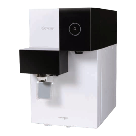
Product characteristics and specifications 2-3 Dimensions P-220R/L [235 mm(W) X 404 mm(D) X 400 mm(H)] Coway co., Ltd... - Page 14 MEMO Coway co., Ltd...
-
Page 15: Product Installation
Product installation 3. Product installation 3-1 Installation materials 3-1-1 Parts Accessories Items Remark Drain Hose Antibacterial Filter Coway co., Ltd... -
Page 16: Installation Method
Product installation 3-2 Installation method 3-2-1 Precautions on installation The water tank capacity of this water purification system has been designed for home use. It is prohibited to install the system for medium/large business or public use. (If the water purification system is used beyond its capacity, a water shortage and/or shortened filter life may occur as a result.) Install the product at least 10 cm away from the wall and on a firm and level floor. Installation water pressure - P-220R: A tap water pressure of 69 kpa or more - P-220L: T he feed water supply pressure should be at least 137 kpa for the purification system to work properly, to provide enough purified water. The Installation distance from the tap water supply - If the tap water pressure is 137 kPa or less : The height should be less than 3 m and the distance should be less than 5 m. - If the tap water pressure is 137 kPa or more : The height should be less than 3 m and the distance should be less than 25 m. Do not install the system in a location exposed to direct sunlight, freezing temperatures or excessive moisture. If the system is installed for the first time or is being relocated, read the User Manual again before installation. Only connect the power cord to the voltage rating that matches it on the rating plate. Make sure to connect the feed water inlet hose to the cold water pipe. - If the feed water inlet hose is connected to the warm water pipe with a water temperature of 40 °C or higher, the filters may be damaged. - Page 17 Product installation Flushing the filters (when installing the product, replacing the filter or providing customer service) - Neo-sense filter/Innocence filter : C lose the valve (feed water valve) of the installation adapter. Separate the product and the feed water line. Connect the tube connected to the installation adapter to the filter to be flushed. Open the feed water valve to flush the filter. (1 min) Never tap the filter to prevent damage to the block. - Membrane filter (RO) : C lose the valve (feed water valve) of the installation adapter. Separate the product and the feed water line. Connect the tube connected to the installation adapter to the filter to be flushed. Install the non-potable water valve to the membrane filter. (It is installed by default.) Open the feed water valve to flush the filter. (5 min) - Membrane filter (UF) : C lose the valve (feed water valve) of the installation adapter. Separate the product and the feed water line. Connect the tube connected to the installation adapter to the filter to be flushed. Open the feed water valve to flush the filter. (3 min) Coway co., Ltd...
-
Page 18: Installing The Product
Product installation 3-2-2 Installing the product Follow the instruction for installation Main water supply valve Main water voltage rating that supply valve matches it on the rating plate. voltage rating that matches it on the rating plate. Connect the orange color inlet tubing 1 to the tap water supplying pipe. Connect the outlet tubing(P-220R/L) 2 . Outlet tubing (Blue, P-220R/L) Inlet tubing (Orange) Coway co., Ltd... -
Page 19: How To Use
Product installation 3-3 How to use Only connect the power cord to the voltage rating that matches it on the rating plate. To drink the room water When you push the cup-touch lever, you can drink the room water. Explanation Reference picture 1. To extract a fixed amount of water If you press the fixed quantity extraction button, the water bottle is filled with a fixed amount of water for approximately 1 minute. Press the fixed quantity extraction button again to stop the water extraction. 2. To extract water Push the cup-touch-lever of the faucet to extract filtrated water. Coway co., Ltd... - Page 20 MEMO Coway co., Ltd...
-
Page 21: Disassembling And Refitting
4-1 Disassembling and refitting information 4-1-1 Disassembling and refitting information - Exercise caution not to damage or deform any parts when disassembling the system. - Refit the system in the reverse order of disassembling. Before disassembling the product - Block the main water by closing the main water supply valve. - Completely drain the water from the water tank. If the water is splashed during the repair, insulation may deteriorate, resulting in danger. - Please unplug. - When disassembling and refitting the unit with its side touching the ground, perform the job on a working cloth. Without the working cloth, the product may get scratches. Safety checking after the service - Check that screws, parts, and wiring are in their original positions. - Check that the wire coverings are not damaged. - After refitting, check that the water purification works. - Check the tubing for water leaks. - Check that all switches operate normally. - After the service, refit the product in its original state. 4-1-2 Necessary tools Tool Tool name ‘+’ Cross-head screwdriver ‘-’ Flat-bladed screwdriver Coway co., Ltd... -
Page 22: Disassembling And Reassembling The Product
Disassembling and refitting 4-2 Disassembling and reassembling the product 4-2-1 Disassembling the Top-Cover Assembly Part names Description Reference picture Water- 1) Separate the Water-Vessel Vessel Assembly by pulling it in the Assembly direction of the arrow in the figure. Top-Cover 1) Separate the Top-Cover Assembly Assembly by pulling it in the direction of the arrow in the figure. 2) Separate the clip of the Main Tank-Cap Assembly. Coway co., Ltd... - Page 23 Disassembling and refitting Part names Description Reference picture Top-Cover 3) Separate the Main Tank-Cap Assembly Assembly by pulling it in the direction of the arrow as shown in the figure. 4) Separate the Antibacterial Filter by pulling it in the direction of the arrow as shown in the figure. Front-Cover 1) Remove the 2 screws from the Assembly Front-Cover Assembly. : 2-THT 4X12 2) Separate the Front-Cover Assembly by pulling it in the direction of the arrow as shown in the figure. Coway co., Ltd...
- Page 24 Disassembling and refitting Part names Description Reference picture Front-Cover 3) Separate the connector Assembly connected to the Front-Cover Assembly. 4) Remove the 4 screws from the Front-PBA Assembly. : 4-THT 4X12 Coway co., Ltd...
-
Page 25: Disassembling The Filter Assembly
Disassembling and refitting 4-2-2 Disassembling the Filter Assembly Part names Description Reference picture Filter 1) Remove the 2 screws from the Side-Door R Assembly. : 2-THT 4X10 2) Separate the Auto Drain Control-Valve using a flat-head screwdriver and remove the fitting from the filter. 3) Separate the filter by pulling it in the direction of the arrow as shown in the figure. Coway co., Ltd... -
Page 26: Disassembling The Main Pba Assembly
Disassembling and refitting 4-2-3 Disassembling the Main PBA Assembly Part names Description Reference picture Main PBA 1) Separate the Main PBA-Cover Assembly Assembly by pulling it in the direction of the arrow in the figure. 2) Separate the connector from the Main PBA assembly. 3) Remove the 2 screws from the Main PBA assembly. : 2-THT 4X12 Coway co., Ltd... -
Page 27: Disassembling The Room Water-Faucet Assembly, Room Water-Valve Assembly And Cts Water Level-Sensor Assembly
Disassembling and refitting 4-2-4 Disassembling the Room Water-Faucet Assembly, Room Water-Valve Assembly and CTS Water Level-Sensor Assembly Part names Description Reference picture Room 1) Remove the 2 screws from the Water- Room Water-Faucet Assembly. Faucet : 2-THT 4X12 Assembly 2) Separate the Room Water- Faucet Assembly by pulling it in the direction of the arrow as shown in the figure. Room 1) Remove the 2 screws from the Water-Valve Room Water-Valve Assembly. Assembly : 2-THT 4X12 2) Separate the Room Water-Valve Assembly by pulling it in the direction of the arrow as shown in the figure. Coway co., Ltd... - Page 28 Disassembling and refitting Part names Description Reference picture CTS Water 1) Separate the clip of the CTS Level Sensor Water Level Sensor Assembly Assembly by pulling it in the direction of the arrow in the figure. 2) Separate the CTS Water Level Sensor Assembly by pulling it in the direction of the arrow in the figure. Coway co., Ltd...
-
Page 29: Disassembling The Side-Cover Assembly
Disassembling and refitting 4-2-5 Disassembling the Side-Cover Assembly Part names Description Reference picture Side-Cover 1) Remove the fitting from the R Assembly Main-Tank Assembly using a flat- head screwdriver. 2) Remove the 2 screws from the Main-Tank assembly. : 2-THT 4X12 3) Remove the 3 screws from the Frame. : 3-THT 4X12 4) Remove the 3 screws from the Rear Cover. : 3-THT 4X12 Coway co., Ltd... - Page 30 Disassembling and refitting Part names Description Reference picture Side-Cover 5) Remove the 2 screws from the R Assembly Filter-Cover Assembly. : 2-THT 4X12 6) Separate the Side-Cover R Assembly by pulling it in the direction of the arrow as shown in the figure. Side-Cover 1) Remove the 2 screws from the L Assembly Main-Tank assembly. : 2-THT 4X12 2) Remove the 3 screws from the Frame. : 3-THT 4X12 4-10 Coway co., Ltd...
- Page 31 Disassembling and refitting Part names Description Reference picture Side-Cover L 3) Remove the 3 screws from the Assembly Rear Cover. : 3-THT 4X12 4) Separate the Side-Cover L Assembly by pulling it in the direction of the arrow as shown in the figure. 4-11 Coway co., Ltd...
-
Page 32: Disassembling The Feed Nos-Valve Assembly
Disassembling and refitting 4-2-6 Disassembling the Feed Nos-Valve Assembly Part names Description Reference picture Feed Nos- 1) Separate the connector from the Valve Feed Nos-Valve Assembly. Assembly 2) Remove the fitting from the Feed Nos-Valve Assembly using a flat-head screwdriver. 3) Separate the screw from the Feed Nos-Valve Assembly. : THT 4X12 4-12 Coway co., Ltd... -
Page 33: Troubleshooting
5-1 Checking faults by symptom 5-1-1 Power failure (for AC 220 V) Power failure The buttons and indicators are not turned on. Is the power supply If the voltage is 187 V or less, Check your power supply at voltage of the wall home. it is a power supply defect. outlet normal? Check the distribution If the supplied power is contacts of the electrical irregular or 0 V. outlet and check whether the power is cut. Is the Main PBA input voltage AC 220 V? Is the connection The power connector is not between the power cord and the Fit the connector correctly. properly connected. power wiring connector normal? Check the Main PBA and Has the Main PBA The fuse has blown. replace it if necessary. fuse blown? The Main PBA connector is Check the Main PBA and Is the Main PBA connector not properly connected. replace it if necessary. connection normal? Coway co., Ltd... - Page 34 Troubleshooting Is the FND cable The FND cable connection is Check the FND cable and connection open? not properly connected. replace it if necessary. Is the voltage of the The PBA power circuit is not Check and replace the PBA if Micom PBA DC 5 V? properly connected. necessary. Coway co., Ltd...
-
Page 35: A Water Filtration Failure Or A Water Overflow
Troubleshooting 5-1-2 A water filtration failure or a water overflow A water filtration failure or a water overflow Is the voltage of the The power supply at home is Check the power supplied at electric outlet in the range not normal. home. AC 187 V ~ 253 V? Is the water cut off and the Check the feed water valve feed water valve normal? and open it if necessary. Is the tube Check the tube and replace pressed or folded? it if necessary. Check if the filter becomes Has water passed blocked before its usual through the filter? lifetime and replace it if necessary. Are the water tubes Check the water inlet, outlet connected according to the and other tubes. specifications? Is the SMPS Check and replace it if SMPS DC 24 V voltage normal? necessary. Coway co., Ltd... - Page 36 Troubleshooting Check the back of the valve Is the Feed-NOS under normal water filtration Check and replace it if valve defective? conditions. (Check if there are necessary. any foreign objects). When the water reaches the top of the sensing part of the low/mid water level sensor or the water reaches the Is the water level bottom of the sensing part Check the water level sensor sensor normal? of the full water level/water and replace it if necessary. overflow sensor, the output voltage should be 0 Volt. Otherwise it should be 5 Volt. The Feed/NOS valve Are the voltages of the Check the Main PBA and under normal conditions: valve and pump connector of the DC 24 / 0 Volts replace it if necessary. main PBA normal? Pump: AC 24 Volts Coway co., Ltd...
-
Page 37: Control Specifications
Troubleshooting 5-2 Control Specifications 5-2-1 Basic Specifications Scope These specifications cover the electronic controller (hereafter "PBA") applied to the Woongjin Coway water filtration device (SAVE [P-220R/L]). Operating conditions Item Description Power Refer to the rating plate. Custody -20 °C ~ ±85 °C environment Surrounding temperature Operating -10 °C ~ ±70 °C environment Surrounding Humidity 30 ~ 90 % RH (only in conditions without condensation) Rated time Continuous operation Construction of the power block and major parts Item Description Input voltage Refer to the rating plate. SMPS power Output block DC 5 V, DC 24 V voltage - Refer to the rating plate. - SMPS voltage (DC 5 V, DC 24 V) External input - Water level sensor: Detects the low and full levels. - Page 38 Troubleshooting Buttons and indicators Item Description Blue LED (Backlight) Tact switch (Extraction button) Buttons There is one extraction button and it is used to extract water (Select/Cancel). The indicator consists of a button with a blue backlight and shows the current status and error information. Display Status Indicator Description sequence The indicator remains Low water off until the status is level changed. The indicator remains Mid/high Indicator on until the status is water level changed. Blinks until the extraction is completed or canceled. Extraction (Beginning: Blinks at 1 ◐ is in second intervals) progress (3 seconds before the end: The indicator blinks at 400 ms intervals) Coway co., Ltd...
- Page 39 Troubleshooting Item Description Display Status Indicator Description sequence The indicator briefly blinks twice and then stays on for a while. ◐-◐-- Normal (The interval when - mode blinking briefly: 200 ms, the period for turning on: Indicator 1 sec.) The indicator blinks 3 times and then shows the ◐-◐-◐ current status Test mode (Blinks at 1 second intervals) In the display sequence column, the represents OFF, represents ON and ◐ represents blinking. Coway co., Ltd...
- Page 40 - After supplying power, the signal from the water level sensor is ignored for approximately 3 seconds while waiting for the stabilization of the sensor operation. - The low and full water level sensors only work when the corresponding water level is detected for approximately 3 seconds. - The overflow sensor only works when a water overflow is detected for approximately 20 seconds or a non-overflow is detected for approximately 3 seconds. 3) Feed valve control - Low water level status: T he feed valve is immediately turned on and the water filtration is started. - Mid water level status: T he feed valve is turned on immediately and the water filtration is started. H owever, if the water level changes from full to mid level, the feed valve is turned on in approximately 15 minutes. - Full water level status: The feed valve is turned off to cut the water supply. H owever, if the water level changes from mid to full, the feed valve is turned off after approximately 3 seconds. 4) Nos valve control - If the overflow sensor detects a water overflow for 20 seconds continuously, the Nos valve is turned on and the water supply is cut off. - The low water level sensor returns to normal. Coway co., Ltd...
- Page 41 Troubleshooting Function Detailed operation 5) Extraction valve control (fixed amount extraction function) Water level - I f the extraction button is pressed, the extraction valve is turned on and and valve approximately 1,000 cc of water is extracted. control : The function is only selected when the input continues for 1 second : The function is only canceled when the input continues for 0.1 seconds: - If the extraction button is pressed, the beeper sound (ding~) is heard. - The fixed amount extraction function only works when the water level is mid or higher. : I f the fixed amount extraction function is available, the indicator LED is turned on to indicate that the extraction function is available. : I f the extraction button is pressed when the water level is low, the alarm beeper sound (ding ding ~~) is heard indicating that the extraction function is not available. - While extracting, the indicator LED blinks at 1 second intervals to indicate that water is being extracted. Coway co., Ltd...
- Page 42 ⇑ ⇓ 3 seconds after the full water level is detected. Detection Non- Non- Re-filtration detection detection operation When the low ⇑ ⇓ ⇓ water level is detected and the full water level is not detected for 15 minutes Non- Non- Non- Re-filtration detection detection detection operation Once the low ⇓ ⇓ ⇓ water level is detected, the feed valve is turned on. 5-10 Coway co., Ltd...
- Page 43 Detection A water level sensor detection defect This is indicated when ⇑ ⇓ ⇑ The LED blinks this occurs three times 3 times (at 200 in succession ms intervals) (However, if this & the beeper occurs once or twice, Non- Non- Detection sound plays only the Nos-Feed detection detection (ding ding valve works without an ding~) ⇓ ⇓ ⇑ error indication. The indicator represents the water level as full.) Sensor detection indication: [1, ⇑ ] Sensor detection failure indication: [0, ⇓ ] If a water overflow is detected, the Nos valve is unconditionally turned on to cut the water supply. 5-11 Coway co., Ltd...
- Page 44 Overflow sensor - Cancellation - Cancellation : W hen the input continues for 3 : W hen the input continues for 1 seconds seconds After the full water level is detected, Once the full water level is detected, the feed valve is turned off after 3 the feed valve is turned off. seconds Feed valve If the water level is changed from full Once the water level is changed from to medium level, the feed valve is full to medium level, the feed valve is turned on after 15 minutes. turned on. - When the low level sensor causes an error once - When the feed valve causes an An error is indicated once any error is Error indication error 3 times detected - When the low water level sensor causes an error three times in succession 5-12 Coway co., Ltd...
- Page 45 MEMO 5-13 Coway co., Ltd...
-
Page 46: Exploded View And Parts List
Exploded view and parts list 6. Exploded view and parts list 6-1 Exploded view and parts list This document is Coway’s technical property. Only the person approved by the company may use this document. Coway co., Ltd... - Page 47 Exploded view and parts list Parts List Description Remark NEO-SENSE FILTER-8 INCH(S) MEMBRANE FILTER-RO 8 INCH(S) INNO-SENSE FILTER-8 INCH(S) COVER-BASE ASSY TANK-MAIN ASSY SENSOR-CTS Water Low Level(T) ASSY SENSOR-CTS Water High Level(U) ASSY SENSOR-CTS Water Over Level(V) ASSY FRAME VALVE-ROOM WATER ASSY PACKING-CONNETOR FAUCET-ROOM WATER ASSY COVER-FILTER ASSY VALVE-FEED NOS ASSY COVER-REAR VALVE-AUTOMATION DRAIN CONTROL PBA-MAIN ASSY COVER-MAIN PBA ASSY COVER-SIDE R ASSY DOOR-SIDE R ASSY COVER-SIDE L CAP-MAIN TANK ASSY COVER-FRONT ASSY PBA-FRONT ASSY COVER-TOP ASSY VESSEL-WATER BOTTLE ASSY BOOSTER PUMP E-LPS Coway co., Ltd...
- Page 48 MEMO Coway co., Ltd...
-
Page 49: Parts Location Diagrams
Parts location diagrams 7. Parts location diagrams 7-1 Electrical wiring diagram This document is Coway’s technical property. Only the person approved by the company may use this document. Coway co., Ltd... -
Page 50: Cable Specification
Parts location diagrams 7-2 Cable Specification 1. Harness - SMPS Remaining (connection) 2. Harness - Front PBA Connection Remaining (connection) 3. Harness - Front PBA (connection) Remaining Coway co., Ltd... - Page 51 Parts location diagrams 4. Harness - FEED, NOS Valve (connection) 5. Haress - LPS Extension Coway co., Ltd...
-
Page 52: Water Piping Diagram
Parts location diagrams 7-3 Water piping diagram 7-3-1 P-220R 7-3-2 P-220L Coway co., Ltd... -
Page 53: Pba Location Diagram
Parts location diagrams 7-4 PBA location diagram 7-4-1 MAIN PBA 1 CN10 2 CN2 3 CN3 Feed/NOS Valve Extract Valve Low Level Sensor Pin No. Signal Pin No. Signal Pin No. Signal DC 24 V DC 24 V DC 5 V SIGNAL SIGNAL SIGNAL DC 24 V SIGNAL Coway co., Ltd... - Page 54 Parts location diagrams 4 CN4 5 CN5 6 CN1 Full Level Sensor Overflow Sensor Display Pin No. Signal Pin No. Signal Pin No. Signal SIGNAL SIGNAL SIGNAL SIGNAL DC 5 V DC 5 V SIGNAL SIGNAL SIGNAL SIGNAL SIGNAL 7 CN7 8 CN8 DC IN Booster Pump Pin No. Signal Pin No. Signal DC 24 V DC 5 V DC 24 V DC 24 V Coway co., Ltd...
-
Page 55: Smps Pba
Parts location diagrams 7-4-2 SMPS PBA 1 CN101 2 CN201 AC IN DC OUT Pin No. Signal Pin No. Signal 220 V~ 220 V~ DC 5 V DC 24 V DC 24 V Coway co., Ltd... - Page 56 MEMO Coway co., Ltd...
-
Page 57: Circuit Diagrams
Circuit diagrams 8. Circuit diagrams 8-1 MAIN PBA This document is Coway’s technical property. Only the person approved by the company may use this document. Coway co., Ltd... -
Page 58: Smps Pba
Circuit diagrams 8-2 SMPS PBA This document is Coway’s technical property. Only the person approved by the company may use this document. Coway co., Ltd... -
Page 59: Reference Information
Reference information 9. Reference information 9-1 Names of each part Front / Rear Fixed Quantity Extraction Button Room(Ambient) Extraction Faucet Cup-touch Lever Water Bottle Top Cover Power Cord Outlet (Blue, P-220R/L) Inlet(Orange) Coway co., Ltd... -
Page 60: Functions And Reference Information
Removes organic/inorganic ionic materials, germs, viruses and heavy metals in Filter function the water. Water filtration capacity - 2 0 % ~ 30 % water flow reduction (on the basis of the membrane capacity (on the basis of standard specifications) TDS 100 ppm of - T DS removal rate 90-3 % (Pump Free Mem.) the tap water) Filter name Inno-Sense Filter 8 inch (S) Filter Material Polyethylene + Active carbon Improves the taste of the water, eliminates odors and minimizes fine particles in Filter function the water tanks - 8 0 % or higher residual chlorine elimination rate (based on 2 ppm of residual Water filtration chlorine) capacity - T he same water filtration condition as the JIS S 3201 (on the basis of : T he status of fine particles when the water flow rate is reduced and residue TDS 100 ppm of from evaporation is generated (when the water flows through the Innocence the tap water) filter continuously). Coway co., Ltd... - Page 61 Reference information Filter name Antibacterial Filter Filter material Antibacterial ceramic Suppresses the proliferation of micro organisms in the water tank and Filter function enhances hygiene and the taste of the water. Filter name UF Membrane Filter 8 inch (S) Filter function Removes micro-organisms, rust and suspended solids in water. Coway co., Ltd...
-
Page 62: Water Filtration Process
Reference information 9-2-2 Water Filtration Process The filter is the core technology of the filtration system. If you don’t use qualifying filter or if you use an old filter that has expired, the system performance may degrade. The 5-step Water filtering system(P-220R/L) STEP 1, 2 : NEO-SENSE FILTER This neo-sense filter has the function to reduce aesthetic chlorine, odor, volatile organic compounds(VOC’s). STEP 3 : RO MEMBRANE FILTER RO membrane filter has the function to reduce water contaminants such as pentavalent arsenic, barium, cadmium, selenium, radium 226/228, trivalent chromium, hexavalent chromium, lead, nitrate/nitrite. STEP 4 : INNO-SENSE FILTER This inno-sense filter has the functions to reduce smell induction material and to improve taste of water. It also has the function to reduce aesthetic chlorine, volatile organic compounds(VOC’s). STEP 5 : ANTIBACTERIAL FILTER * Reject Water ANTIBACTERIAL Outlet FILTER NEO-SENSE RO MEMBRANE INNO-SENSE ANTIBACTERIAL FILTER FILTER * FILTER FILTER The Antibacterial filter contains silver, which is known to inhibit the propagation of microorganisms and to maintain the integrity of the filter. Uses of reject water - The reject water should be used for cleaning the restroom, the house, clothes, or purposes other than drinking. -
Page 63: After Services
Reference information 9-3 After services 9-3-1 Filter Replacement Filter Filter is a critical component for a water filtration system. Replacing authorized filters at a specified replacement cycle is important to maintain the water quality, and a proper system operation. Please replace filters at a specified replacement cycle. Filter replacement cycle If the filter is not regularly replaced, it may degrade the water quality from the product. The source water quality can shorten the filter replacement period. [P-220R/L] Part No. Names of Filter Usable Period WJNF8-S Neo-sense filter 6 months WJMF8-20-S RO Memberance filter 20 months WJIF8-S Inno-sense filter 18 months WJCC-03 Antibacterial filter * 12 months The Antibacterial filter contains silver, which is known to inhibit the propagation of microorganisms and to maintain the integrity of the filter. About filter replacement cycle The filter replacement cycle described above is not the filter quality warranty period but the expected cycle (life) that the filter shows its original performance. Therefore, the filter replacement cycle may be reduced for the area with the poor water quality or more water consumption. Coway co., Ltd... -
Page 64: Filter Replacement Method
Reference information 9-3-2 Filter Replacement Method Explanation Reference picture 1. Close the main water supply valve after unplugging the power cord, and drain the water inside of the water filtration device. 2. Lift the front draining door and release 4 fixed screw using the phillips driver. Pull and then lift up the side cover to separate it. Coway co., Ltd... - Page 65 Reference information Explanation Reference picture 3. After separating the fitting connected to the filter to replace, please replace the filter. (Separate the fitting using the proper tool.) By changing the filter and connecting the fitting and the hose precisely, check that there is no leakage and drain the first filtered water necessarily. 4. Please fit the groove of the front cover. Fasten the 4 fixing screws firmly with a Philips screwdriver. Please be sure to use the new filter after cleansing. - Neo-sense filter : P lease mount it after cleaning with the main water for about 1 minutes. - Inno-sense filter : P lease mount it after cleaning with the main water for about 3 minutes. - RO Membrane filter : P lease install the non-potable water valve and wash the filter with water for about 5 minutes. Coway co., Ltd...
-
Page 66: Cleaning Method
Reference information 9-3-3 Cleaning Method Storage tank Explanation Reference picture 1. Unplug the power cord. Close the main water supply valve. 2. Please empty the water tank completely using the draining hose. Coway co., Ltd... - Page 67 Reference information Explanation Reference picture 3. Open the upper cover of the product and open the storage tank cover. Coway co., Ltd...
- Page 68 Reference information Explanation Reference picture 4. Please install again after separating the antibacterial filter * from the water tank cover and shaking and cleansing in the room water. 5. Please wipe the surface of the storage tank with soft clothes. 9-10 Coway co., Ltd...
- Page 69 Reference information Explanation Reference picture 6. Drain completely using the draining hose after washing out the storage tank with the taken water. 7. Close the water tank cover and assemble the fixing clip. The Antibacterial filter contains silver, which is known to inhibit the propagation of microorganisms and to maintain the integrity of the filter. 9-11 Coway co., Ltd...
- Page 70 Reference information Explanation Reference picture 8. Close the upper cover, plug in the power cord, and open the main water supply valve. Confirm that filtrated water has been extracted from one of the faucets. Close the storage tank cover completely. - A worm or a foreign body can be entered. When you clean the storage tank, don’t use the medicine or the detergent. If you don’t clean the medicine or the detergent cleanly, it can be harmful to the body. - Keep the surroundings cleanly and clean the storage tank once per two months. 9-12 Coway co., Ltd...
Need help?
Do you have a question about the P-220R and is the answer not in the manual?
Questions and answers