Aiwa NSX-BL14 Service Manual
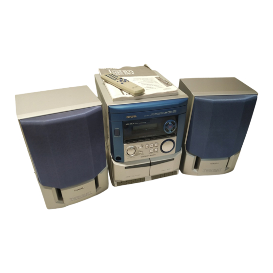
Compact disc stereo cassette receiver
Hide thumbs
Also See for NSX-BL14:
- Service manual (38 pages) ,
- Service manual (42 pages) ,
- Service manual (30 pages)
Table of Contents
Advertisement
SERVICE MANUAL
COMPACT DISC STEREO
CASSETTE RECEIVER
SYSTEM
CASSEIVER
NSX-BL13<LH>
NSX-BL14<HR>
NSX-BL14<V>
• This Service Manual is the "Revision Publishing" and replaces "Simple
Manual" NSX-BL14(HR, V), (S/M Code No. 09-005-428-8T3) and
NSX-BL13(LH), (S/M Code No. 09-005-428-8T4).
• If requiring information about the CD mechanism, see Service Manual
of AZG-1 (S/M Code No. 09-001-335-3NC).
BASIC CD
CD
MECHANISM
AZG-1
CX-SNBL13
YZA3RNDM
AZG-1
CX-NBL14
ZA3RNDM
AZG-1
CX-NBL14
ZA3RNDM
S/M Code No. 09-006-428-8R3
NSX-BL14
NSX-BL13
BASIC TAPE MECHANISM : ZZM-2
BASIC CD MECHANISM : AZG-1
BASIC TAPE
SPEAKER
MECHANISM
ZZM-2
SX-SNBL17
YPR1NM
ZZM-2
SX-NBL11
PR1NM
ZZM-2
SX-NBL11
PR1NM
HR,V
LH
REMOTE
CONTROLLER
RC-ZAS02
Advertisement
Table of Contents

Related Manuals for Aiwa NSX-BL14


Summary of Contents for Aiwa NSX-BL14
- Page 1 ZA3RNDM PR1NM • This Service Manual is the “Revision Publishing” and replaces “Simple Manual” NSX-BL14(HR, V), (S/M Code No. 09-005-428-8T3) and NSX-BL13(LH), (S/M Code No. 09-005-428-8T4). • If requiring information about the CD mechanism, see Service Manual of AZG-1 (S/M Code No. 09-001-335-3NC).
-
Page 2: Specifications
SPECIFICATIONS <FM tuner section><HR,LH> <Compact disc player section>2 Tuning range 87.5 MHz to 108 MHz Laser Semiconductor laser (λ =780 nm) Usable sensitivity (IHF) 13.2 dBf D-A converter 1 bit dual Antenna terminals 75 ohms (unbalanced) Signal-to-noise ratio 85 dB (1 kHz, 0 dB) Harmonic distortion 0.05 % (1 kHz, 0 dB) <FM tuner section><V>... -
Page 3: Protection Of Eyes From Laser Beam During Servicing
PROTECTION OF EYES FROM LASER BEAM DURING SERVICING CAUTION This set employs laser. Therefore, be sure to follow carefully Use of controls or adjustments or performance of proce- the instructions below when servicing. dures other than those specified herein may result in hazardous radiation exposure. -
Page 4: Note On Before Starting Repair
NOTE ON BEFORE STARTING REPAIR 1. Forced discharge of electrolytic capacitor of power supply block When repair is going to be attempted in the set that uses relay circuit in the power supply block, electric potential is kept charged across the electrolytic capacitors (C101, 102) even though AC power cord is removed. - Page 5 In such a case, check also if the POWER AMPLIFIER circuit or power supply circuit has any abnormalities or not. 2-2. Regarding reset There are cases that the machine does not work correctly because the MICROCOMPUTER is not reset even though the AC power cord is re-inserted, or the software reset (pressing the STOP key + POWER key) is performed.
-
Page 6: Electrical Main Parts List
ELECTRICAL MAIN PARTS LIST REF. NO. PART NO. KANRI DESCRIPTION REF. NO. PART NO. KANRI DESCRIPTION 87-010-407-080 CAP, ELECT 33-50 M 11L SME<V> 87-010-247-080 CAP, ELECT 100-50V<LH> 8A-NFA-615-010 C-IC,M38B57MCH-E236FP 87-010-406-080 CAP, ELECT 22-50<HR,V> 87-A21-397-010 IC,STK490-070<LH> 87-010-247-080 CAP, ELECT 100-50V<LH> 87-A21-419-040 C-IC,NJM14558MD-TE2 87-010-384-080 CAP, ELECT 100-25M11LSME<HR,V>... - Page 7 REF. NO. PART NO. KANRI DESCRIPTION REF. NO. PART NO. KANRI DESCRIPTION C311 87-010-598-080 C-CAP,S 0.068-16VRK C799 87-010-407-080 CAP, ELECT 33-50V C312 87-010-598-080 C-CAP,S 0.068-16VRK C800 87-012-369-080 C-CAP,S 0.047-50F C313 87-010-188-080 CAP,CHIP 6800P C801 87-010-403-080 CAP, ELECT 3.3-50V C314 87-010-188-080 CAP,CHIP 6800P C802 87-012-369-080...
- Page 8 REF. NO. PART NO. KANRI DESCRIPTION REF. NO. PART NO. KANRI DESCRIPTION FFE831 A8-8ZA-190-030 8ZA-1 FEUNM<HR> C213 87-010-404-040 CAP,E 4.7-50 SME FFE831 A8-8ZA-191-030 8ZA-1 YFEUNM<LH> C401 87-010-186-080 C-CAP,S 4700P-50 K B<HR> FFE831 A8-6ZA-193-130 6ZA-1 FEVNM<V> C402 87-010-060-040 CAP,E 100-16 M 7L SRA<HR> J101 87-A60-602-010 JACK,DIA6.3 BLK ST W/SW TC...
-
Page 9: Chip Resistor Part Code
CHIP RESISTOR PART CODE Chip Resistor Part Coding Figure Resistor Code Value of resistor Chip resistor Dimensions (mm) Symbol Wattage Type Tolerance Resistor Code Form 1/16W 1005 0.35 1/16W 1608 0.45 1/10W 2125 1.25 0.45 1/8W 3216 0.55 TRANSISTOR ILLUSTRATION E C B S D G E C B... - Page 10 FL (10-BT-224GNK) GRID ASSIGNMENT AND ANODE CONNECTION GRID ASSIGNMENT – –...
- Page 11 ANODE CONNECTION – –...
- Page 12 IC BLOCK DIAGRAM IC,M62495AFP IC,LA1844L-A IC,LC72131D – 12 –...
-
Page 13: Wiring - 1 (Main)
WIRING - 1 (MAIN)<HR> – 13 –... -
Page 14: Schematic Diagram - 1 (Main 1 / 2 : Amp Section)
SCHEMATIC DIAGRAM – 1 (MAIN 1 / 2 : AMP SECTION)<HR> – 14 –... -
Page 15: Schematic Diagram - 2 (Main 2 / 2 : Tuner Section)
SCHEMATIC DIAGRAM – 2 (MAIN 2 / 2 : TUNER SECTION)<HR> MW / SW – 15 –... -
Page 16: Wiring - 2 (Main)
WIRING - 2 (MAIN)<LH> – 16 –... - Page 17 SCHEMATIC DIAGRAM – 3 (MAIN 1 / 2 : AMP SECTION)<LH> – 17 –...
- Page 18 SCHEMATIC DIAGRAM – 4 (MAIN 2 / 2 : TUNER SECTION)<LH> – 18 –...
- Page 19 WIRING - 3 (MAIN)<V> – 19 –...
- Page 20 SCHEMATIC DIAGRAM – 5 (MAIN 1 / 2 : AMP SECTION)<V> – 20 –...
- Page 21 SCHEMATIC DIAGRAM – 6 (MAIN 2 / 2 : TUNER SECTION)<V> – 21 –...
- Page 22 WIRING - 4 (FRONT) – 22 –...
- Page 23 SCHEMATIC DIAGRAM – 7 (FRONT) – 23 –...
- Page 24 WIRING - 5 (PT)<HR> – 24 –...
-
Page 25: Schematic Diagram - 8 (Pt)
SCHEMATIC DIAGRAM – 8 (PT)<HR> Q31,32 RESET – 25 –... - Page 26 WIRING - 6 (PT)<LH> – 26 –...
- Page 27 SCHEMATIC DIAGRAM – 9 (PT)<LH> – 27 –...
- Page 28 WIRING - 7 (PT)<V> – 28 –...
- Page 29 SCHEMATIC DIAGRAM – 10 (PT)<V> – 29 –...
- Page 30 WIRING - 8 (DECK)
- Page 31 IC DESCRIPTION IC, M38B57MCH-E236FP Description Pin No. Pin Name I-SIG RDS signal level A/D input. (Not used) I-HOLD Hold voltage level A/D input. I-SW (CD) CD mecha SW A/D input. I-DISH CD turn-table position check A/D input. I-KEY2 KEY2 A/D input. I-KEY1 KEY1 A/D input.
- Page 32 Pin No. Pin Name Description O-DISH_R CD turn-table reverse turn output. O-DISH_F CD turn-table forward turn output. I-SUBQ Sub code-Q data input. O-CD_CE CD DSP chip enable output. I-WRQ CD WRQ input. O-CLK (CD) CD control clock output. O-DATA (CD) CD control data output.
- Page 33 ADJUSTMENT <TUNER / DECK> A MAIN C.B<LH,V> L801 L802 TP4 (DC) IC801 TP3 (DC) IC301 (CLK) L951(1/3) TP8 (LCH) TP1(VT) TP9 (RCH) FFE831 DECK–1 R/P/E, DECK-2 P HEAD A MAIN C.B<HR> TC943 L801 L802 TC941 TP4 (DC) L941 IC801 L942 TP3 (DC) IC301 L953...
- Page 34 B FRONT C.B FL201 TP5 (K-SCAN) IC101 L101 SFR701 < TUNER SECTION > 1. Clock frequency Check 6. MW Tracking Adjustment<HR> Settings : • Test point : TP2 (CLK) Settings : • Test point : TP8(Lch), TP9(Rch) • Adjustment location : Method : Set to AM 1710kHz(LH), MW 1602kHz(HR,V) and check that the test point is 2160kHz ±...
- Page 35 < DECK SECTION > 12. Tape Speed Adjustment (DECK 1) 17. REC/PB Sensitivity Check (DECK 1) Settings : • Test tape : TTA–100 Settings : • Test tape : TTA–602 • Test point : TP8(Lch), TP9(Rch) • Test point : TP8(Lch), TP9(Rch) •...
-
Page 36: Mechanical Exploded View
MECHANICAL EXPLODED VIEW 1 / 1 AZG-1 31 30 P.C.B P.C.B LH ONLY PLATE,EARTH ZZM-2 HT-SINK V ONLY HLDR1 V 0NLY HLDR2 P.C.B WIRE,BINDER P.C.B HR ONLY P.C.B HT-SINK, FIN-S CHAS, MAIN P.C.B P.C.B HR ONLY – –... -
Page 37: Mechanical Parts List
TAPPING SCREW, BVT2+3-15<LH> 17 8A-NFA-018-010 REFLECTOR,ECO D 87-078-191-010 S-SCREW,IT+4-10 18 8A-NFZ-008-010 KEY,POWER E 87-067-688-010 BVTT+3-6 19 87-CE3-023-010 BADGE,AIWA 30N SILV F 87-723-096-410 QT2+3-10W/O SLOT BL 20 8A-NFZ-002-010 PANEL,TRAY H G 87-721-096-410 QT2+3-10 GLD<LH> 21 8A-NFA-208-010 GUIDE,FL 100-25 ANFA H 87-721-097-410... -
Page 38: Tape Mechanism Exploded View
TAPE MECHANISM EXPLODED VIEW 1 / 1 TERMINAL,LB1 TERMINAL,LB1 – –... -
Page 39: Tape Mechanism Parts List
TAPE MECHANISM PARTS LIST 1 / 1 REF. NO. PART NO. KANRI DESCRIPTION REF. NO. PART NO. KANRI DESCRIPTION 1 8Z-ZM1-254-210 SPR-C,REEL R 41 8Z-ZM1-234-010 FLY-WHL,ZZM-1 2 8Z-ZM1-225-110 GEAR,REEL R 42 8Z-ZM1-267-010 SHAFT,CAPSTAN 2 3 8Z-ZM1-253-110 SPR-C,AUTO SENSOR 43 8Z-ZM1-228-010 GEAR,SLIP T-UP B 4 8Z-ZM1-217-110 LEVER,AUTO SENSOR... - Page 40 SPEAKER DISASSEMBLY INSTRUCTIONS Type.1 Type.4 TOOLS Insert a flat-bladed screwdriver into the position indicated by the arrows and remove the panel. Remove the screws of each speaker 1 Plastic head hammer unit and then remove the speaker units. 2 (() flat head screwdriver 3 Cut chisel How to Remove the PANEL, FR Type.2...
-
Page 41: Accessories / Package List
SPEAKER PARTS LIST SX-NBL11(Y1SL) / SX-NBL17(YJSC9,YJSC) / SX-SNBL17(YLSC2M) REF. NO. PART NO. KANRI DESCRIPTION 1 8A-NSB-001-010 PANEL,FR 2 8A-NSB-003-010 GRILLE,FRAME ASSY 3 8Z-NSL-603-010 SPKR, W 120<YJSC,YJSC9> 3 8A-NSL-603-010 SPKR, CERAMIC<YLSC2M> 3 8A-NSL-606-010 SPKR, W120<Y1SL> 4 87-NS7-611-010 CORD,SPKR<Y1SL,YLSC2M> 5 8A-NSL-602-010 SPKR, 120<YLSC2M> 6 8A-NSK-015-010 CORD,BUSH<YLSC2M>... - Page 42 2–11, IKENOHATA 1–CHOME, TAITO-KU, TOKYO 110, JAPAN TEL:03 (3827) 3111 9630472 0251431 Printed in Singapore...