Brother mfc8440 Service Manual
Hide thumbs
Also See for mfc8440:
- User manual (426 pages) ,
- Software user's manual (183 pages) ,
- Quick setup manual (52 pages)

Related Manuals for Brother mfc8440


Summary of Contents for Brother mfc8440
-
Page 1: Service Manual
SERVICE MANUAL MODEL: MFC8440/8840D/8840DN DCP8040/8045D/8045DN Read this manual thoroughly before maintenance work. Keep this manual in a convenient place for quick and easy reference at all times. - Page 2 Specifications are subject to change without notice. Trademarks: The brother logo is a registered trademark of Brother Industries, Ltd. Apple, the Apple Logo, and Macintosh are trademarks, registered in the United States and other countries, and TrueType is a trademark of Apple computer, Inc.
- Page 3 PREFACE This publication is a Service Manual covering the specifications, construction, theory of operation, and maintenance of the Brother machine. It includes information required for field troubleshooting and repair--disassembly, reassembly, and lubrication--so that service personnel will be able to understand machine function, to rapidly repair the machine and order any necessary spare parts.
-
Page 4: Table Of Contents
TABLE OF CONTENTS TABLE OF CONTENTS REGULATION.....................viii SAFETY INFORMATION ................x CHAPTER 1 GENERAL ................1-1 OVERVIEW ......................1-1 SPECIFICATIONS....................1-3 General ..........................1-3 General (Continued)......................1-3 Print Media ........................1-4 Copy ..........................1-4 Fax ........................... 1-5 Scanner ..........................1-6 Printer..........................1-6 Interfaces ......................... 1-7 Consumable Items ...................... - Page 5 MFC-8440/8840D/8840DN, DCP-8040/8045D/8045DN SERVICE MANUAL 3.2.2 For Parallel Interface Cable Users ® (For Windows 95/98/98SE/Me/2000 Professional/XP) ...........2-13 ® 3.2.3 For Windows NT Workstation Version 4.0 Users ............2-18 3.2.4 For Network Interface Cable Users ® (For Windows 95/98/98SE/Me/NT/2000 Professional/XP) ..........2-20 ® 3.2.5 For USB Interface Cable Users (For Mac OS 8.6 to 9.2 Users) ........2-23 ®...
- Page 6 TABLE OF CONTENTS 2.4.9 Rear cover sensor......................3-21 2.4.10 HP sensor ......................... 3-21 Drum Unit ........................3-22 2.5.1 Photosensitive drum......................3-22 2.5.2 Primary charger......................... 3-22 2.5.3 Transfer roller........................3-22 2.5.4 Cleaner ..........................3-22 Toner Cartridge ......................3-22 Print Process........................3-22 2.7.1 Charging ...........................
- Page 7 MFC-8440/8840D/8840DN, DCP-8040/8045D/8045DN SERVICE MANUAL 3.28 Paper Feeder ......................... 4-72 3.29 Frame L / Drive Unit....................... 7-79 3.30 Reversing Release Solenoid (MFC-8840D/8840DN, DCP-8045D/8045DN only) ..4-83 3.31 Thermistor ASSY ......................4-84 3.32 Fan Motor 60 Unit LV / Fan Motor 60 Unit..............4-84 3.33 Frame R .........................
- Page 8 95/98/Me Peer to Peer (HP JetAdmin Compatible Method) Troubleshooting ..6-59 ® 10.8 Windows 95/98/Me/NT 4.0/2000 Peer to Peer Print (NetBIOS) Troubleshooting ..6-60 10.9 Brother Internet Print (TCP/IP) Troubleshooting ............6-60 ® 10.10 Windows 95/98/Me/2000/XP IPP Troubleshooting............6-60 10.11 Novell Netware Troubleshooting ..................6-61 10.12 AppleTalk Troubleshooting.....................
- Page 9 MFC-8440/8840D/8840DN, DCP-8040/8045D/8045DN SERVICE MANUAL 3.11 Fine Adjustment of Scan Start/End Positions (Maintenance mode 54)......7-18 3.12 CCD Scanner Area Setting (Maintenance mode 55) ............. 7-20 3.13 EEPROM Customizing (Maintenance mode 74) ............7-21 3.14 Printing out of Machine Log Information (Maintenance mode 77)........7-22 3.15 Display of the Equipment’s Log Information (Maintenance mode 80)......
-
Page 10: Regulation
This product complies with FDA radiation performance standards, 21 CFR Subchapter J. The label for Chinese manufactured products MANUFACTURED: BROTHER Corporation (Asia) Ltd. Shenzen Buji Nan Ling Factory Gold Garden Ind., Nan Ling Village, Buji, Rong Gang, Shenzen, CHINA This product complies with FDA radiation performance standards, 21 CFR Subchapter J. - Page 11 MFC-8440/8840D/8840DN, DCP-8040/8045D/8045DN SERVICE MANUAL IEC 825 (220-240V MODEL ONLY) This printer is a Class I laser product as defined in IEC 825 specifications. The label shown below is attached in countries where required. CLASS 1LASERP RODUCT APPAREIL Å LASER DE CLASSE 1 LASER KLASSE 1 PRODUKT This printer has a laser diode which emits invisible laser radiation in the Laser Unit.
-
Page 12: Safety Information
SAFETY INFORMATION SAFETY INFORMATION CAUTION FOR LASER PRODUCT (WARNHINWEIS FUR LASER DRUCKER) CAUTION: When the machine during servicing is operated with the cover open, the regulations of VBG 93 and the performance instructions for VBG 93 are valid. CAUTION: In case of any trouble with the laser unit, replace the laser unit itself. To prevent direct exposure to the laser beam, do not try to open the enclosure of the laser unit. - Page 13 MFC-8440/8840D/8840DN, DCP-8040/8045D/8045DN SERVICE MANUAL DEFINITIONS OF WARNINGS, CAUTIONS AND NOTES The following conventions are used in this service manual: WARNING Indicates warnings that must be observed to prevent possible personal injury. CAUTION: Indicates cautions that must be observed to service the printer properly or prevent damage to the printer.
-
Page 14: Chapter 1 General
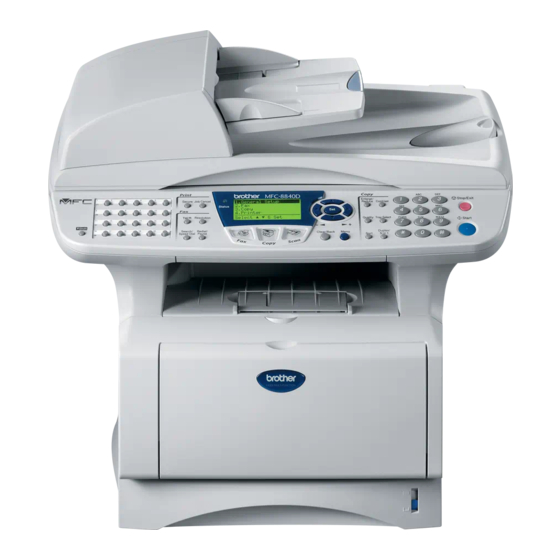
MFC-8440/8840D/8840DN, DCP-8040/8045D/8045DN SERVICE MANUAL CHAPTER 1 GENERAL OVERVIEW <Front View> ADF document support extension Automatic document feeder (ADF) Control panel ADF document output support flap Face-down output tray support flap Document cover Front cover release button Manual feed tray (MFC-8440, DCP-8040) Multi-purpose tray (MP tray) (MFC-8840D/8840DN, Power switch... - Page 15 CHAPTER 1 GENERAL <Inside View (Document Cover Open)> Document cover White film Scanner lock lever Glass strip Document guidelines Scanner glass Fig. 1-3...
-
Page 16: Specifications
MFC-8440/8840D/8840DN, DCP-8040/8045D/8045DN SERVICE MANUAL SPECIFICATIONS General Memory Capacity 32 MB 1 DIMM slot; Memory expandable up to 160 MB Optional Memory Up to 50 pages Automatic Document Paper Tray 250 Sheets (20 lb) Multi-Purpose Tray 50 Sheets (20 lb) (MFC-8840D/8840DN, DCP-8045D/8045DN only) Manual Feed Tray Single sheet (20 lb) (MFC-8440, DCP-8040 only) -
Page 17: Print Media
CHAPTER 1 GENERAL Print Media <Paper Tray> Paper Input • Paper type: Plain paper, recycled paper and transparencies, envelopes (Manual Feed/Multi-purpose Tray) • Paper size: A4, Letter, Legal, B5 (ISO), B5 (JIS), Executive, A5, A6, B6 (ISO) Weight: 16 - 28 lb (60 - 105 g/m ) (Paper Tray) For more details, see Paper specifications for each paper tray on page 1-10. -
Page 18: Fax
Speed-Dial One time Automatic Redial Auto Answer 0, 1, 2, 3 or 4 rings Public switched telephone network. Communication Source Up to 600 pages (Brother #1 Chart) Memory Transmission Out of Paper Up to 600 pages (Brother #1 Chart) Reception... -
Page 19: Scanner
® HP LaserJet) and BR-Script (PostScript ) Level 3 ® Windows 95/98/98SE/Me/2000 Professional/XP and Windows Printer Driver ® Workstation Version 4.0 driver supporting Brother Native Compression mode and bi-directional capability ® ® ® Apple Macintosh Quick Draw Driver and PostScript (PPD) for OS 8.6-9.2/OS X 10.1/10.2.1 or Greater... -
Page 20: Interfaces
10/100 BASE-TX Auto Negotiation TCP/IP, IPX/SPX, AppleTalk, DLC/LLC RARP, BOOTP, DHCP, APIPA, NetBIOS, WINS LPR/LPD, Port9100, SMTP/POP3 SMB(NetBIOS/ IP), IPP, SSDP, Rendezvous, FTP MIBII as well as Brother private MIB TELNET, SNMP, HTTP, TFTP Included Utilities: BRAdmin Professional and Web Based Management NOTE: •... -
Page 21: Computer Requirements
USB is not supported under Windows 95 or Windows NT WS 4.0. All registered trademarks referenced herein are the property of their respective companies. For the latest drivers, go to the Brother Solutions Center at http://solutions.brother.com/ ® ® Application software is different for Windows and Macintosh Scanning is supported in 10.2.1 or greater. -
Page 22: Paper
MFC-8440/8840D/8840DN, DCP-8040/8045D/8045DN SERVICE MANUAL 2.12 Paper 2.12.1 Type and size of paper The machine loads paper from the installed paper tray, manual feed tray, multi-purpose tray or optional lower tray. Tray type Model name Paper tray (Tray #1) MFC-8440/8840D/8840DN, DCP-8040/8045D/8045DN Manual feed tray MFC-8440, DCP-8040 Multi-purpose tray (MP tray) -
Page 23: 2.12.4 Paper Specifications For Each Paper Tray
CHAPTER 1 GENERAL 2.12.4 Paper specifications for each paper tray MFC-8440 MFC-8840D/8840DN Model DCP-8040 DCP-8045D/8045DN Plain paper, Bond paper, Recycled paper, Multi-purpose tray Envelope , Labels, and Transparency Plain paper, Bond paper, Paper types Recycled paper, Manual feed tray Envelope, Labels, and Transparency Paper tray Plain paper, Recycled paper, and Transparency... -
Page 24: Printable Area
MFC-8440/8840D/8840DN, DCP-8040/8045D/8045DN SERVICE MANUAL CAUTION: When you are choosing print media, be sure to follow the information given below to prevent any paper jams, print quality problems or machine damage; • It is recommended to use long-grained paper for the best print quality. If short-grained paper is being used, it might be the cause of paper jams. - Page 25 CHAPTER 1 GENERAL The table below shows the printable areas when printing on Portrait for each paper size. Size 215.9 mm 279.4 mm 203.2 mm 279.4 mm 6.35 mm 4.2 mm 8.5” 11.0” 8.0” 11.0” 0.25” 0 mm 0.16” Letter (2,550 dots) (3,300 dots) (2,400 dots)
- Page 26 MFC-8440/8840D/8840DN, DCP-8040/8045D/8045DN SERVICE MANUAL Landscape Physical page Printable area Logical page Physical page length Maximum logical page length Distance from edge of physical page to edge of logical page 1-13...
-
Page 27: 2.13.2 Pcl6/Br-Script3 Emulation
CHAPTER 1 GENERAL The table below shows the printable areas when printing on Landscape for each paper size. Size 279.4 mm 215.9 mm 269.3 mm 215.9 mm 5.0 mm 4.2 mm 11.0” 8.5” 10.6” 8.5” 0.2” 0 mm 0.16” Letter (3,300 dots) (2,550 dots) (3,180 dots) -
Page 28: Print Speeds With Various Settings
MFC-8440/8840D/8840DN, DCP-8040/8045D/8045DN SERVICE MANUAL 2.14 Print Speeds with Various Settings Print speed of the machine is up to 16/17 ppm when loading A4 or Letter size paper from the paper tray in the plain paper mode. Actual print speed varies depending on the media type or paper size as shown in the tables below;... -
Page 29: Toner Cartridge Weight Information
CHAPTER 1 GENERAL 2.15 Toner Cartridge Weight Information Toner Cartridge Weight (approx weight) Before M4JN000001B, M4JN000001C (Serial No.) TN3060/TN570 TN3030/TN540 Brand new Toner Cartridge Weight 827.5g 772.5g Toner Weight at Brand New Toner Cartridge 197.5±2.5g 142.5±2.5g Toner Cartridge Weight at Toner Near Empty 693.5-698.5g 693.5-698.5g Remain Toner Weight at Toner Near Empty... -
Page 30: Serial No. Descriptions
< ID for year > 2003 2004 < ID for factory > Kariya Plant Mie Brother BIUK Buji Nan Ling Factory (1) Machine: Printed on the label attached on the rear of the main body <MODEL NO.> < SERIAL NO. >... - Page 31 CHAPTER 1 GENERAL (4) Toner cartridge: Imprinted on the aluminum bag 3 A 3 0 YEAR MONTH DATE FACTORY ID NO. Printed on the bar code label attached on the toner cartridge CARTRIDGE M 3 9 A 0 0 0 1 9 9 A PRODUCTION INFO.
-
Page 32: Chapter 2 Installation And Basic Operation
MFC-8440/8840D/8840DN, DCP-8040/8045D/8045DN SERVICE MANUAL CHAPTER 2 INSTALLATION AND BASIC OPERATION CONDITIONS REQUIRED FOR INSTALLATION Power Supply • The source voltage must stay within ±10% of the rated voltage shown on the rating plate. • The power cord, including extensions, should not exceed 5 meters (16.5 feet). •... -
Page 33: Unpacking
CHAPTER 2 INSTALLATION AND BASIC OPERATION UNPACKING When unpacking the machine, check to see that all of the following components are included in the carton. Quick Setup Guide CD-ROMs ® For Windows (1 piece) ® For Macintosh (1 piece) 1. Control Panel 4. -
Page 34: Install The Machine
MFC-8440/8840D/8840DN, DCP-8040/8045D/8045DN SERVICE MANUAL INSTALL THE MACHINE You need to implement hardware setup and driver installation to use the machine. ® ® Firstly, identify the Operating System on your computer. (Windows 95/98/Me, Windows NT ® 4.0, Windows 2000/XP and Macintosh)Then, purchase the appropriate interface cable (Parallel, USB or Network) for your computer. -
Page 35: Install The Automatic Document Feed (Adf) Support
CHAPTER 2 INSTALLATION AND BASIC OPERATION 3.1.1 Install the Automatic Document Feed (ADF) support (1) Open the ADF cover. ADF cover Fig. 2-2 Fig. 2-3 (2) Slide ADF support into the groove on ADF. Fig. 2-4... -
Page 36: Install The Drum Unit Assembly
MFC-8440/8840D/8840DN, DCP-8040/8045D/8045DN SERVICE MANUAL (3) Close the ADF cover. Fig. 2-5 3.1.2 Install the drum unit assembly (1) Open the front cover by pressing the front cover release button. (2) Unpack the drum unit assembly. Remove the protective part. (3) Rock it from side to side several times to distribute the toner evenly inside the assembly. Fig. -
Page 37: Load Paper Into The Paper Tray
CHAPTER 2 INSTALLATION AND BASIC OPERATION 3.1.3 Load paper into the paper tray (1) Pull the paper tray completely out of the machine. (2) While pressing the paper guide release lever, slide the adjusters to fit the paper size. Check that the guides are firmly in the slots on the tray. Paper guide release lever Universal guide release button... -
Page 38: Release The Scanner Lock
MFC-8440/8840D/8840DN, DCP-8040/8045D/8045DN SERVICE MANUAL 3.1.4 Release the scanner lock (1) Push the lever up to unlock the scanner. (Refer to Fig.2-11.) Scanner lock lever Fig. 2-11... -
Page 39: Installing The Driver & Software
If it does the installation will automatically continue. • If the installation does not continue automatically, please open the installer menu again by double-clicking the setup.exe program from the root directory of the Brother CD-ROM, and continue from Step (4). ®... - Page 40 If you click No the Scan keys on the machine will be disabled. NOTE: Even if you select NO, later you will be able to launch the Brother Control Center to use the Scan to key by double clicking the Smart UI icon on the desktop. This loads the Brother Control Center to the task tray.
- Page 41 If you click No the Scan keys on the machine will be disabled. NOTE: Even if you select NO, later you will be able to launch the Brother Control Center to use the Scan to key by double clicking the Smart UI icon on the desktop. This loads the Brother Control Center to the task tray.
- Page 42 There will be two Brother printer drivers listed in the Printers selection. • The driver with "Printer" after the model name (ex. Brother MFC-8840D Printer) is the Brother Native Driver. The Brother Native Drivers have been installed and the installation is now complete.
- Page 43 There will be two Brother printer drivers listed in the “Printers” selection. • The driver with Printer after the model name (ex. Brother MFC-8840D Printer) is the Brother Native Driver. The Brother Native Drivers have been installed and the installation is now complete.
-
Page 44: For Parallel Interface Cable Users
If an error message appears during the installation process, or if you have previously installed the MFL-Pro Suite, you will first have to uninstall it. From the Start menu, select Programs, Brother, Brother MFL-Pro Suite, Uninstall, and then follow the instructions on the screen. 2-13... - Page 45 If you click No the Scan keys on the machine will be disabled. NOTE: Even if you select NO, later you will be able to launch the Brother Control Center to use the Scan to key by double clicking the Smart UI icon on the desktop. This loads the Brother Control Center to the task tray.
- Page 46 If you click No the Scan keys on the machine will be disabled. NOTE: Even if you select NO, later you will be able to launch the Brother Control Center to use the Scan to key by double clicking the Smart UI icon on the desktop. This loads the Brother Control Center to the task tray.
- Page 47 (21) Un-check the Automatically detect and install my Plug and Play printer selection and then click Next. (22) Select BMFC (Brother MFL Port) from the pull down window for the Printer Port Selection and then click Next. (23) Click on Have Disk.
- Page 48 There will be two Brother printer drivers listed in the Printers selection. • The driver with "Printer" after the model name (ex. Brother MFC-8840D Printer) is the Brother Native Driver. The Brother Native Drivers have been installed and the installation is now complete.
-
Page 49: For Windows Nt Workstation Version 4.0 Users
If an error message appears during the installation process, or you have previously installed MFL-Pro Suite, you will first have to uninstall it. From the Start menu, select Programs, Brother, Brother MFL-Pro Suite, Uninstall, and then follow the instructions on the screen. 2-18... - Page 50 If you click No the Scan keys on the machine will be disabled. NOTE: Even if you select NO, later you will be able to launch the Brother Control Center to use the Scan to key by double clicking the Smart UI icon on the desktop. This loads the Brother Control Center to the task tray.
-
Page 51: For Network Interface Cable Users (For Windows ® 95/98/98Se/Me/Nt/2000 Professional/Xp)
If an error message appears during the installation process, or if you have previously installed the MFL-Pro Suite, you will first have to uninstall it. From the Start menu, select Programs, Brother, Brother MFL-Pro Suite, Uninstall, and then follow the instructions on the screen. 2-20... - Page 52 95/98/98SE/Me/NT/2000 Users follow step (25). NOTE: ® The Network Scanning feature is not supported in Windows 95 or NT. ® For Windows XP Users Only The Brother PC-FAX, Printer and Scanner drivers have been installed and the installation is now complete. 2-21...
- Page 53 If you click No the Scan keys on the machine will be disabled. NOTE: Even if you select NO, later you will be able to launch the Brother Control Center to use the Scan to key by double clicking the Smart UI icon on the desktop. This loads the Brother Control Center to the task tray.
-
Page 54: For Usb Interface Cable Users (For Mac Os 8.6 To 9.2 Users)
On the right side of the Chooser, select the printer to which you want to print. Close the Chooser. The Brother PC-FAX Send, Printer and Scanner drivers have been installed. (11) To install Presto! Page Manager, click the Presto! PageManager icon and follow on the Screen instructions. -
Page 55: For Usb Interface Cable Users (For Mac Os X 10.1/10.2.1 Or Greater Users)
Insert the supplied CD-ROM for the operating system you are using into your CD-ROM drive. Double-click the Start Here OS X icon to install the printer driver, Scanner driver, Brother PC-FAX Send and Remote Setup program. If the language screen appears, select your language. -
Page 56: For Network Interface Cable Users (For Mac Os 8.6 To 9.2 Users)
Turn on the machine by plugging in the power cord. Turn the power switch on. Open the Chooser from the Apple menu. (10) Click the Brother Laser (AT) icon, and then select BRN_xxxxxx_P1. Close the Chooser. NOTE: xxxxxx are the last six digits of the Ethernet address. -
Page 57: Os X 10.1/10.2.1 Or Greater Users)
Ethernet address. (14) Select Quit Printer Center from the Printer Center menu. The setup is now complete. NOTE: ® For Mac OS 10.2.1 or greater Users Only Please visit http://solutions.brother.com/ for information about using Rendezvous. 2-26... -
Page 58: Chapter 3 Theory Of Operation
MFC-8440/8840D/8840DN, DCP-8040/8045D/8045DN SERVICE MANUAL CHAPTER 3 THEORY OF OPERATION ELECTRONICS General Block Diagram Fig. 3-1 shows a general block diagram. Host Computer Control Centronics USB interface panel parallel interface Control Section Printer data Fax data Line NCU* Speaker ADF unit Scanner unit Laser printing unit Paper... -
Page 59: Main Pcb Block Diagram
CHAPTER 3 THEORY OF OPERATION Main PCB Block Diagram Fig. 3-2 shows the block diagram of the main PCB. A S I C CPU Core (SPARClite 133MHz) Oscillator 66.6MHz Reset Circuit Address Decoder DRAM Control Program + Font ROM 1MB, 4MB, 8MB Timer Network Program FIFO... -
Page 60: Main Pcb
MFC-8440/8840D/8840DN, DCP-8040/8045D/8045DN SERVICE MANUAL Main PCB For the entire circuit diagram of the main PCB, see APPENDIX 4.1 to 4.7 ‘MAIN PCB CIRCUIT DIAGRAM’ in this manual. 1.3.1 A Fujitsu 32bit RISC CPU, SPARClite is built in the ASIC. While the CPU is driven with a clock frequency of 66.66 MHz in the user logic block, it itself runs at 133.33 MHz, which is generated by multiplying the source clock by two. -
Page 61: Ieee1284
CHAPTER 3 THEORY OF OPERATION 1.3.3 IEEE1284 Stores the data received from the PC into DRAM as controlled by the DMA controller. It is applicable to both normal receiving and bi-directional communication (nibble mode, byte mode, ECP mode). 74LVX161284, 3.3V 5.0V level shifter IC stores the pull-up resistance in signal wire at the connector side Printer... -
Page 62: Flash Rom
MFC-8440/8840D/8840DN, DCP-8040/8045D/8045DN SERVICE MANUAL 1.3.5 Flash ROM A 16Mbit flash ROM (x 16bit) is fitted. Fig. 3-7 1.3.6 SDRAM Fig. 3-8... -
Page 63: Optional Ram
CHAPTER 3 THEORY OF OPERATION 1.3.7 Optional RAM A 32bit (100 pin) DIMM can be fitted as optional RAM. The main PCB has one slot and the capacity of DIMM can be from 16MB to 128MB. DQ[31-0] 1-8C/7D/4-7E DIMM DQ[0] VDD3 DQ[1] DQ[2]... -
Page 64: Eeprom
MFC-8440/8840D/8840DN, DCP-8040/8045D/8045DN SERVICE MANUAL 1.3.8 EEPROM The EEPROM is BR24126 type of two-wire method with a 8192 x 8bit configuration. Aurora Fig. 3-10 1.3.9 Reset circuit The reset IC is a R3112N281C. The reset voltage is 2.8V (typ.) and the LOW period of reset is 22.4ms (typ.) VDD3 C103... -
Page 65: 1.3.12 Video I/O
CHAPTER 3 THEORY OF OPERATION 1.3.12 Video I/O The video signal output from the ASIC is reversed through a transistor and output after being corrected by the buffer IC. VDD3 VDD3 VDD3 VDD5 VDD5 1/10W C103 C103 TP233 C471 DATA1 TP230 TP231 TC7SH08FU... -
Page 66: 1.3.14 Power Supply
MFC-8440/8840D/8840DN, DCP-8040/8045D/8045DN SERVICE MANUAL 1.3.14 Power supply +5V is generated by the 3-pin regulator from astable 7V supplied from the LVPS. +5V is used for the IEEE1284 interface, the LD PCB and the engine PCB. In addition, +1.9V is generated by the 3-pin regulator from 3.3V supplied from the LVPS. -
Page 67: Engine Pcb
CHAPTER 3 THEORY OF OPERATION Engine PCB The gate array which transforms the serial signal from the main PCB into the parallel signal is mounted on the engine PCB. The engine PCB controls the following parts by using the transferred signal data; •... -
Page 68: Power Supply
MFC-8440/8840D/8840DN, DCP-8040/8045D/8045DN SERVICE MANUAL Power Supply 1.5.1 Low-voltage power supply The power supply uses a switching regulation system to generate the regulated DC power (+3.3V, +8V [non regulated] and +24V), which are converted from the AC line. The regulated output is listed below; Regulated Output +3.3V / 1.5A +8V / 0.4A... -
Page 69: High-Voltage Power Supply
CHAPTER 3 THEORY OF OPERATION 1.5.2 High-voltage power supply The high-voltage power supply generates and outputs the voltages and currents for the charging, development and transfer functions. For the circuit diagram of the high-voltage power supply PCB, see APPENDIX 4.18 or 4.19 ‘HIGH-VOLTAGE POWER SUPPLY PCB CIRCUIT DIAGRAM’... -
Page 70: Mechanics
MFC-8440/8840D/8840DN, DCP-8040/8045D/8045DN SERVICE MANUAL MECHANICS Overview of Printing Mechanism Scanner motor Heat roller Corona wire LASER UNIT Second eject roller Blade Outer chute MP DRUM UNIT Rear cover Development roller Supply roller Paper feed pinch roller First eject roller Regist front actuator FIXING UNIT First feed pinch roller Pressure roller... -
Page 71: Scanner Mechanism
CHAPTER 3 THEORY OF OPERATION Scanner Mechanism PF roller holder ASSY LF roller 1 ASSY Front sensor LF roller 2 ASSY actuator ASSY Eject roller ASSY ADF cover Guide shaft Top cover HP sensor Pulley ASSY CCD module Belt Scanner base Fig. -
Page 72: Paper Transfer
MFC-8440/8840D/8840DN, DCP-8040/8045D/8045DN SERVICE MANUAL Paper Transfer 2.3.1 Paper supply The paper pick-up roller picks up one sheet of paper from the paper tray every time it is rotated and feeds it to the paper feed roller. First feed roller First feed pinch roller Paper feed pinch roller Paper feed roller Regist front... -
Page 73: Paper Eject
CHAPTER 3 THEORY OF OPERATION 2.3.3 Paper eject After the printing image on the photosensitive drum is transferred onto the paper, the paper is fed to the fixing unit to fix unfixed toner onto the paper. Afterwards, the paper is ejected from the fixing unit by the first eject roller in the fixing unit. The paper eject actuator detects whether the paper is ejected correctly or not. -
Page 74: Sensors
MFC-8440/8840D/8840DN, DCP-8040/8045D/8045DN SERVICE MANUAL Sensors 2.4.1 Cover sensors Detect opening and closing of the front cover. Front cover sensor Fig. 3-25 2.4.2 Toner sensors Detects if there is toner in the toner cartridge. The toner sensor at the left side emits light through the window on the left side of the toner cartridge, then the toner sensor at the right side receives it when the toner is low. -
Page 75: Cassette Sensor / Paper Empty Sensor
CHAPTER 3 THEORY OF OPERATION 2.4.3 Cassette sensor / Paper empty sensor Detect if the paper tray is installed. They also detect if there is paper in the paper tray . Paper empty sensor Cassette sensor PCB ASSY Cassette sensor Fig. -
Page 76: Mp-Pe Sensor
MFC-8440/8840D/8840DN, DCP-8040/8045D/8045DN SERVICE MANUAL 2.4.5 MP-PE sensor Detects if there is paper in the MP tray. MP-PE sensor PCB ASSY Feed MP unit Fig. 3-29 2.4.6 Document cover sensor Document cover sensor Fig. 3-30 3-19... -
Page 77: Document Front Sensor /Document Rear Sensor
CHAPTER 3 THEORY OF OPERATION 2.4.7 Document front sensor /Document rear sensor Document front sensor Document rear sensor Fig. 3-31 2.4.8 DX-sensor PCB ASSY DX-sensor PCB ASSY Fig. 3-32 3-20... -
Page 78: Rear Cover Sensor
MFC-8440/8840D/8840DN, DCP-8040/8045D/8045DN SERVICE MANUAL 2.4.9 Rear cover sensor Rear cover sensor Fig. 3-33 2.4.10 HP sensor HP sensor Fig. 3-34 3-21... -
Page 79: Drum Unit
CHAPTER 3 THEORY OF OPERATION Drum Unit 2.5.1 Photosensitive drum Generates the latent electrostatic image and develops the image on the drum surface. 2.5.2 Primary charger Forms a uniform charge on the drum surface. (1) Corona wire Generates the ion charge on the drum. (2) Grid Spreads the ion charge evenly over the drum surface. -
Page 80: Exposure Stage
MFC-8440/8840D/8840DN, DCP-8040/8045D/8045DN SERVICE MANUAL 2.7.2 Exposure stage After the drum is positively charged, it is exposed to the light emitted from the laser unit. Drum Laser beam Paper Laser beam f θ lens Laser detector Polygon mirror Laser diode Motor Lens Fig. -
Page 81: Developing
CHAPTER 3 THEORY OF OPERATION 2.7.3 Developing Developing causes the toner to be attracted to the electrostatic image on the drum so as to transform it into a visible image. The developer consists of a non-magnetic toner. The development roller is made of conductive rubber and the supply roller (which is also made of conductive sponge) rotate against each other. -
Page 82: Fixing Stage
MFC-8440/8840D/8840DN, DCP-8040/8045D/8045DN SERVICE MANUAL 2.7.5 Fixing stage The image transferred to the paper by static electricity is fixed by heat and pressure when passing through the heat roller and the pressure roller in the fixing unit. The thermistor keeps the surface temperature of the heat roller constant by detecting the surface temperature of the heat roller and turning on or off the halogen heater lamp. -
Page 83: Chapter 4 Disassembly And Re-Assembly
MFC-8440/8840D/8840DN, DCP-8040/8045D/8045DN SERVICE MANUAL CHAPTER 4 DISASSEMBLY AND RE-ASSEMBLY SAFETY PRECAUTIONS To avoid creating secondary problems by mishandling, follow the warnings and precautions below during maintenance work. WARNING (1) Always turn off the power switch and unplug the power cord from the power outlet before accessing any parts inside the printer. -
Page 84: Disassembly Flow
CHAPTER 4 DISASSEMBLY AND RE-ASSEMBLY DISASSEMBLY FLOW SIDE COVER L/R AC CORD FRONT COVER ASSY (MFC-8440, DCP-8040 only) DRUM UNIT JOINT COVER MP UNIT (MFC-8840D/8840DN, DCP-8045D/8045DN only) PAPER TRAY REAR COVER SENSOR DX FEED ASSY (MFC-8840D/8840DN, DCP-8045D/8045DN only) LASER UNIT ACCESS COVER/BATTERY BASE PLATE / LV INSULATION SHEET DRIVER PCB ACCESS COVER... -
Page 85: Disassembly Procedure
MFC-8440/8840D/8840DN, DCP-8040/8045D/8045DN SERVICE MANUAL DISASSEMBLY PROCEDURE AC Cord (1) Disconnect the AC cord from the machine. Machine AC cord Fig. 4-1 Drum Unit (1) Open the front cover and remove the drum unit. Drum unit Front cover Fig. 4-2... -
Page 86: Paper Tray
CHAPTER 4 DISASSEMBLY AND RE-ASSEMBLY Paper Tray (1) Close the front cover and pull out the paper tray. (2) Remove the paper from the paper tray. Front cover Paper tray Fig. 4-3 (3) Remove the pad holder and the separation pad spring from the paper tray. Pad holder Separation pad spring Paper tray... - Page 87 MFC-8440/8840D/8840DN, DCP-8040/8045D/8045DN SERVICE MANUAL NOTE: When replacing/re-assembling the pad holder ZL2 ASSY, remove the old grease and apply a suitable amount of grease referring to the figure below; Paper pick-up roller Grease: Molykote PG-662 Paper tray (4 mm dia.ball) Fig. 4-5 (4) Remove the four bind B M4x12 Taptite screws, and then remove the paper tray front cover.
- Page 88 CHAPTER 4 DISASSEMBLY AND RE-ASSEMBLY (5) Remove the two cup B M3x10 Taptite screws, and then remove the paper tray cover. Paper tray Taptite, cup B M3x10 Paper tray cover Taptite, cup B M3x10 Fig. 4-7 (6) Remove the pressure roller holder. Pressure roller holder Paper tray Flat screwdriver...
- Page 89 MFC-8440/8840D/8840DN, DCP-8040/8045D/8045DN SERVICE MANUAL (7) Remove the pressure roller collar. (8) Remove the pressure roller shaft. Pressure roller shaft Pressure roller collar Pressure roller holder ASSY Fig. 4-9 (9) Remove the scratch spongy holder ASSY from the pressure roller holder. (10) Remove the two scratch spongy springs.
- Page 90 CHAPTER 4 DISASSEMBLY AND RE-ASSEMBLY (12) Remove the two cup M2.6x5 Taptite screws. (13) Release the lock lever, and then unhook the catches of the two side guide racks. Taptite, cup M2.6x5 Side guide L Taptite, cup M2.6x5 Side guide rack Catches Lock lever Paper tray...
- Page 91 MFC-8440/8840D/8840DN, DCP-8040/8045D/8045DN SERVICE MANUAL (15) Unhook the two catches (A) of the pressure plate while pulling the plastic frame outwards, then unhook the other two catches (B) of the plate while pulling the plastic frame outwards to remove the pressure plate ASSY. Catches (A) Pressure plate ASSY Paper tray...
- Page 92 CHAPTER 4 DISASSEMBLY AND RE-ASSEMBLY NOTE: When re-assembling the pressure plate ASSY, ensure that the paper indicator arm is under the pressure plate. CAUTION: When unhooking the catches to remove the pressure plate, do not bend the pressure plate, gently ease the plastic cover. If the pressure plate is deformed, paper feeding problems may occur.
- Page 93 MFC-8440/8840D/8840DN, DCP-8040/8045D/8045DN SERVICE MANUAL (19) Remove the cup B M3x8 Taptite screw, and then remove the side guide gear and the friction spring. (20) Remove the two side guide racks. Taptite, cup B M3x8 Side guide gear Side guide rack Friction spring Side guide rack Fig.
- Page 94 CHAPTER 4 DISASSEMBLY AND RE-ASSEMBLY NOTE: • When re-assembling the side guide racks, they should both be aligned so that the wide end of the racks are in line with the inside edge of the paper guide release slots in the tray before refitting the spring and gear.
- Page 95 MFC-8440/8840D/8840DN, DCP-8040/8045D/8045DN SERVICE MANUAL (24) Remove the paper rear guide. Paper tray Paper rear guide Fig. 4-20 4-13...
-
Page 96: Dx Feed Assy (Mfc-8840D/8840Dn, Dcp-8045D/8045Dn Only)
CHAPTER 4 DISASSEMBLY AND RE-ASSEMBLY DX Feed ASSY (MFC-8840D/8840DN, DCP-8045D/8045DN only) (1) Remove the DX feed ASSY. DX feed ASSY Fig. 4-21 (2) Remove the four bind B M3x8 Taptite screws, and then remove the DX roller holder and three pressure rollers. (3) Remove the three pressure roller springs. - Page 97 MFC-8440/8840D/8840DN, DCP-8040/8045D/8045DN SERVICE MANUAL NOTE: Set pressure roller, and assemble pressure roller spring after assembling DX roller holder. Pressure roller spring Pressure roller Tray feed ZL2 Fig. 4-23 (4) Remove the two bind B M3x8 Taptite screws, and then remove the guide plate stopper. (5) Remove the two left guide spring 2.
- Page 98 CHAPTER 4 DISASSEMBLY AND RE-ASSEMBLY (6) Remove the side regist guide. (7) Remove the left guide plate ASSY and DX paper switch pull arm. Side regist guide Left guide plate ASSY DX paper switch pull arm Hooks Tray feed ZL2 Fig.
-
Page 99: Access Cover / Battery
CAUTION: • There is a danger of explosion if the battery is incorrectly replaced. • Use Brother genuine spare part when you replace the battery. • Do not disassemble, recharge or dispose of in fire. • Used battery should be disposed of according to local regulations. -
Page 100: Driver Pcb Access Cover
CHAPTER 4 DISASSEMBLY AND RE-ASSEMBLY Driver PCB Access Cover (1) Remove the bind B M4x12 Taptite screw, and then remove the driver PCB access cover. Driver PCB access cover Taptite, bind B M4x12 Fig. 4-29 4-18... -
Page 101: Adf Unit
MFC-8440/8840D/8840DN, DCP-8040/8045D/8045DN SERVICE MANUAL ADF Unit (1) Remove the document tray ASSY. Hooks Document tray ASSY Hooks Fig. 4-30 (2) Disconnect the three connectors. (3) Remove the cup B M3x10 Taptite screw, and then remove the ground wire. Driver PCB ASSY Connector Taptite, cup B M3x10 Ground wire... - Page 102 CHAPTER 4 DISASSEMBLY AND RE-ASSEMBLY (4) Remove the two bind B M4x12 Taptite screws, and then remove the document cover. Taptite, bind B M4x12 Document cover Fig. 4-32 (5) Remove the hinge base R. (6) Remove the three cup B M3x10 Taptite screws, and then remove the hinge arm R. (7) Remove the three cup B M3x10 Taptite screws, and then remove the hinge ASSY L.
- Page 103 MFC-8440/8840D/8840DN, DCP-8040/8045D/8045DN SERVICE MANUAL (8) Remove the document hold ASSY and document hold spring. (9) Remove the two cup B M3x10 Taptite screws, and then remove the rear sensor cover. Taptite, cup B M3x10 Hooks Hooks Document hold ASSY Document hold spring Document hold spring Rear sensor cover...
- Page 104 CHAPTER 4 DISASSEMBLY AND RE-ASSEMBLY (11) Remove the document ejection tray. Document ejection tray Document cover LGL Fig. 4-36 (12) Remove the cup B M3x10 Taptite screw, and then remove the side cover F. (13) Remove the cup B M3x10 Taptite screw, and then remove the side cover R. Hook Side cover R Hook...
- Page 105 MFC-8440/8840D/8840DN, DCP-8040/8045D/8045DN SERVICE MANUAL (14) Disconnect the four connectors. (15) Remove the cup S M3x6 Taptite screw, and then remove the ground wire. (16) Remove the four cup B M3x10 Taptite screws, and then remove the ADF chute ASSY. Taptite, cup B M3x10 ADF motor ADF chute ASSY Connector...
- Page 106 CHAPTER 4 DISASSEMBLY AND RE-ASSEMBLY (19) Remove the cup S M3x6 Taptite screw, and then remove the ADF relay PCB ASSY. (20) Remove the three cup S M3x6 Taptite screws, and then remove the motor frame ASSY. (21) Remove the two pan (S/P washer) M3x8 screws, and then remove the ADF motor. Taptite, cup S M3x6 Taptite, cup S M3x6 ADF relay PCB ASSY...
- Page 107 MFC-8440/8840D/8840DN, DCP-8040/8045D/8045DN SERVICE MANUAL (23) Remove the ADF film. (24) Remove the B M3x6 Taptite screw, and then remove the spring plate ADF front A ASSY. (25) Remove the separation rubber, rubber holder and compression spring. (26) Remove the two pressure rollers and pressure roller shaft S. ADF film Taptite, bind B M3x6 Spring plate ADF front A ASSY...
- Page 108 CHAPTER 4 DISASSEMBLY AND RE-ASSEMBLY (28) Remove the conductive bushing, and then remove the LF roller 2 ASSY. (29) Remove the conductive bushing, and then remove the ejection roller ASSY. LF roller 2 ASSY Ejection roller ASSY Conductive bushing PF roller holder Conductive bushing Fig.
- Page 109 MFC-8440/8840D/8840DN, DCP-8040/8045D/8045DN SERVICE MANUAL (33) Remove the film. (34) Remove the document rear sensor, and then disconnect the connector. (35) Remove the document cover sensor. Document rear sensor Connector Film Document cover sensor Document cover LGL Connector Document rear sensor Fig.
-
Page 110: Document Scanner
CHAPTER 4 DISASSEMBLY AND RE-ASSEMBLY Document Scanner NOTE: The disassembly job of the scanner unit should be done in a clean room to prevent dust or dirt from getting into the scanner unit. (1) Disconnect the FFC cable. NOTE: • After disconnecting flat cable(s), check that each cable is not damaged at its end or short-circuited. - Page 111 MFC-8440/8840D/8840DN, DCP-8040/8045D/8045DN SERVICE MANUAL (5) Remove the six cup B M4x12 Taptite screws, and then remove the top cover ASSY. Taptite, cup B M4x12 Top cover ASSY Taptite, cup B M4x12 Taptite, cup B M4x12 Taptite, cup B M4x12 Scanner base ASSY Fig.
- Page 112 CHAPTER 4 DISASSEMBLY AND RE-ASSEMBLY (8) Remove the guide shaft from the CCD module. (9) Release the belt from the pulley ASSY. (10) Remove the belt support rubber, and then remove the belt from the CCD module. (11) Disconnect the FFC cable from the CCD module. NOTE: •...
- Page 113 MFC-8440/8840D/8840DN, DCP-8040/8045D/8045DN SERVICE MANUAL (13) Remove the cup B M3x8 Taptite screw, and then remove the FFC plate. (14) Remove the sponge and FFC cable ASSY. Taptite, cup B M3x8 FFC plate Hook Sponge FFC cable ASSY Scanner base Fig. 4-52 (15) Remove the cup S M3x6 Taptite screw, and then remove the ground wire.
- Page 114 CHAPTER 4 DISASSEMBLY AND RE-ASSEMBLY (18) Remove the two pan (S/P washer) M3x6 screws, and then remove the scanning motor Scanning motor FB Drive plate ASSY Pan (S/P washer) M3x6 Fig. 4-54 (19) Remove the B M3x6 Taptite screw, and then remove the pulley ASSY and pulley spring. Taptite, B M3x6 Pulley ASSY Pulley spring...
-
Page 115: Panel Unit
MFC-8440/8840D/8840DN, DCP-8040/8045D/8045DN SERVICE MANUAL Panel Unit (1) Remove the four cup B M4x12 Taptite screws, and then remove the connector and panel unit. Taptite, cup B M4x12 Panel unit Taptite, cup B M4x12 Panel PCB harness Fig. 4-56 (2) Remove the six cup B M3x8 Taptite screws, and then remove the panel rear cover. Taptite, cup B M3x8 Panel rear cover Taptite, cup B M3x8... - Page 116 CHAPTER 4 DISASSEMBLY AND RE-ASSEMBLY (3) Disconnect the three cables. NOTE: • After disconnecting flat cable(s), check that each cable is not damaged at its end or short-circuited. • When connecting flat cable(s), do not insert them at an angle. After insertion, check that the cables are not at an angle.
- Page 117 MFC-8440/8840D/8840DN, DCP-8040/8045D/8045DN SERVICE MANUAL (5) Remove the backlight holder and the deffusion film. Backlight holder Panel cover Deffusion film Fig. 4-60 (6) Remove the LCD. Panel cover Hooks Hook Hook Hooks Fig. 4-61 4-35...
-
Page 118: Rear Cover C (Mfc-8440, Dcp-8040 Only)
CHAPTER 4 DISASSEMBLY AND RE-ASSEMBLY 3.10 Rear Cover C (MFC-8440, DCP-8040 only) (1) Remove the bind B M4x12 Taptite screw, and then remove the rear cover C. Rear cover C Taptite, bind B M4x12 Fig. 4-62 4-36... -
Page 119: Outer Chute (Mfc-8440, Dcp-8040 Only)
MFC-8440/8840D/8840DN, DCP-8040/8045D/8045DN SERVICE MANUAL 3.11 Outer Chute (MFC-8440, DCP-8040 only) (1) Remove the outer chute. Hook Outer Chute Fig. 4-63 (2) Remove the outer chute tray. Outer Chute Outer chute tray Fig. 4-64 4-37... -
Page 120: Rear Cover Mp Assy / Outer Chute Mp Assy (Mfc-8840D/8840Dn, Dcp-8045D/8045Dn Only)
CHAPTER 4 DISASSEMBLY AND RE-ASSEMBLY 3.12 Rear Cover MP ASSY / Outer Chute MP ASSY (MFC-8840D/8840DN, DCP-8045D/8045DN only) (1) Remove the rear cover MP ASSY. Hook Rear cover MP ASSY Fig. 4-65 (2) Remove the outer chute MP ASSY. Hook Outer chute MP ASSY Fig. -
Page 121: Rear Cover L/R
MFC-8440/8840D/8840DN, DCP-8040/8045D/8045DN SERVICE MANUAL (3) Remove the rear cover MP tray. Rear cover MP ASSY Rear cover MP tray Fig. 4-67 3.13 Rear Cover L/R (1) Remove the two bind B M4x12 Taptite screws, and then remove the rear cover L. (2) Remove the two bind B M4x12 Taptite screws, and then remove the rear cover R. -
Page 122: Side Cover L/R
CHAPTER 4 DISASSEMBLY AND RE-ASSEMBLY 3.14 Side Cover L/R (1) Remove the three bind B M4x12 Taptite screws, and then remove the side cover R. Side cover R Taptite, bind B M4x12 Taptite, bind B M4x12 Taptite, bind B M4x12 Taptite, bind B M4x12 Fig. -
Page 123: Joint Cover
MFC-8440/8840D/8840DN, DCP-8040/8045D/8045DN SERVICE MANUAL 3.15 Joint Cover (1) Disconnect the three connectors. Joint cover Driver PCB ASSY Speaker harness Driver PCB harness Panel PCB harness Main PCB Fig. 4-71 (2) Remove the four bind B M4x12 Taptite screws, and then remove the joint cover. Hook Joint cover Taptite, bind B M4x12... - Page 124 CHAPTER 4 DISASSEMBLY AND RE-ASSEMBLY (3) Remove the speaker hold spring and the speaker. Speaker Speaker hold spring Hook Fig. 4-73 (4) Remove the four bind B M4x12 Taptite screws, and then remove the inner chute. Inner chute Taptite, bind B M4x12 Taptite, bind B M4x12 Hooks Taptite, bind B M4x12...
- Page 125 MFC-8440/8840D/8840DN, DCP-8040/8045D/8045DN SERVICE MANUAL (5) Remove the eject roller ASSY from the joint cover. Eject roller ASSY Joint cover Fig. 4-75 (6) Remove the corrugation pinch roller L, R and pinch roller holder. Corrugation pinch roller L, R Pinch roller holder Inner chute Fig.
- Page 126 CHAPTER 4 DISASSEMBLY AND RE-ASSEMBLY (7) Remove the two bind B M4x12 Taptite screws, and then remove the joint cover front L. (8) Remove the two bind B M4x12 Taptite screws, and then remove the joint cover front R. Joint cover Taptite, bind B M4x12 Taptite, bind B Joint cover front R...
- Page 127 MFC-8440/8840D/8840DN, DCP-8040/8045D/8045DN SERVICE MANUAL (10) Remove the support flap and the support flap S. Support flap Support flap S Fig. 4-79 NOTE: For the way how to attach the additional ribs, refer to “LOCATION TO ATTACH THE ADDITIONAL RIBS” in APPENDIX 4-45...
-
Page 128: Front Cover Assy (Mfc-8440, Dcp-8040 Only)
CHAPTER 4 DISASSEMBLY AND RE-ASSEMBLY 3.16 Front Cover ASSY (MFC-8440, DCP-8040 only) (1) Release the link. (2) Remove the front cover ASSY. Frame Front cover ASSY Link Fig. 4-80 4-46... -
Page 129: Mp Unit (Mfc-8840D/8840Dn, Dcp-8045D/8045Dn Only)
MFC-8440/8840D/8840DN, DCP-8040/8045D/8045DN SERVICE MANUAL 3.17 MP Unit (MFC-8840D/8840DN, DCP-8045D/8045DN only) (1) Disconnect the two connectors. (2) Remove the MP ground spring. (3) Remove the bind B M3x8 Taptite screw and cup S M3x6 Taptite screw. (4) Remove the MP solenoid holder unit. MP ground spring MP solenoid holder unit Engine PCB... - Page 130 CHAPTER 4 DISASSEMBLY AND RE-ASSEMBLY (7) While pushing the MP pressure plate, remove the separation plate ASSY. Separation plate ASSY MP chute ASSY MP pressure plate Fig. 4-83 NOTE: When replacing with the new separation plate ASSY, attach it after peeling the cover paper of double-faced tape.
- Page 131 MFC-8440/8840D/8840DN, DCP-8040/8045D/8045DN SERVICE MANUAL (8) Remove the shaft of the MP front cover ASSY from the drive release link, and then remove the MP front cover ASSY from the MP chute ASSY. MP chute ASSY Drive release link Shaft MP front cover ASSY Shaft Fig.
- Page 132 CHAPTER 4 DISASSEMBLY AND RE-ASSEMBLY (10) Remove the MP tray ASSY. MP chute ASSY MP tray ASSY Fig. 4-87 (11) Remove the MP tray support flap 2 and the MP tray support flap 3 from the MP tray ASSY. MP tray support flap 3 MP tray support flap 2 MP tray ASSY Fig.
- Page 133 MFC-8440/8840D/8840DN, DCP-8040/8045D/8045DN SERVICE MANUAL (12) Open the MP chute ASSY cover. (13) Remove the MP-PE actuator. MP-PE actuator MP chute ASSY Fig. 4-89 (14) Remove the four bind B M4x12 Taptite screws, and then remove the MP chute ASSY. Taptite, bind B M4x12 MP chute ASSY Taptite, bind B M4x12 Fig.
-
Page 134: Rear Cover Sensor
CHAPTER 4 DISASSEMBLY AND RE-ASSEMBLY (15) Remove the cup S M3x6 Tite screws, and then remove the MP gear cover. (16) Remove the MP roller cover. (17) Remove the MP-PE sensor PCB ASSY. MP-PE sensor PCB ASSY Hook Hook (pin) Hook Hook MP roller cover... -
Page 135: Ncu (Mfc-8440/8840D/8840Dn Only)
MFC-8440/8840D/8840DN, DCP-8040/8045D/8045DN SERVICE MANUAL 3.19 NCU (MFC-8440/8840D/8840DN only) (1) Disconnect the connector. (2) Remove the two cup S M3x6 Taptite screws, and then remove the NCU unit. Hook NCU harness NCU unit Taptite, cup S M3x6 Hook Fig. 4-93 (3) Remove the cup S M3x6 Taptite screw, and then remove the NCU shield cover. (4) Remove the two cup S M3x6 Taptite screws, and then disconnect the connector. -
Page 136: Fixing Unit
CHAPTER 4 DISASSEMBLY AND RE-ASSEMBLY 3.20 Fixing Unit (1) Disconnect the heater harness and thermistor harness. (2) Remove the bind B M4x12 Taptite screw and the shoulder screw, and then remove the fixing unit. Fixing unit Shoulder screw Heater harness Taptite, bind B M4x12 Thermistor harness Fig. - Page 137 MFC-8440/8840D/8840DN, DCP-8040/8045D/8045DN SERVICE MANUAL (4) Remove the three cup B M3x10 Taptite screws, and then remove the star wheel holder. Fixing unit Pins Taptite, cup B M3x10 Star wheel holder Fig. 4-97 (5) Remove the cup B M3x12 Taptite screw. (6) Release the thermistor ASSY harness from the hooks.
- Page 138 CHAPTER 4 DISASSEMBLY AND RE-ASSEMBLY NOTE: When re-assembling the thermistor to the FU frame upper, ensure the direction of the thermistor is correct referring to the figure below; FU frame upper Thermistor Thermistor Taptite, cup B M3x12 Fig. 4-99 (8) Remove the two cup B M3x20 Taptite screws. (9) Remove the FU frame upper from the FU frame lower.
- Page 139 MFC-8440/8840D/8840DN, DCP-8040/8045D/8045DN SERVICE MANUAL (10) Remove the two pan (washer) M2.6x6 Taptite screws. (11) Remove the heat roller 25. (12) Remove the halogen lamp. Heat roller 25 Screw, pan (washer) M2.6x6 Colored side 115V:Orange Washer 26 Halogen lamp 230V:Black Screw, pan (washer) M2.6x6 Washer 26 Halogen lamp...
- Page 140 CHAPTER 4 DISASSEMBLY AND RE-ASSEMBLY (13) Remove the HR bearing 25. (14) Remove the HR gear 34. (15) Remove the HR retaining ring 25. (16) Remove the heat roller washer 25. (17) Remove the HR bearing 25. HR bearing 25 HR bearing 25 Heat roller 25 Heat roller washer 25...
- Page 141 MFC-8440/8840D/8840DN, DCP-8040/8045D/8045DN SERVICE MANUAL • When re-assembling the heat roller 25 to the FU frame upper, ensure you do not damage the heat roller 25 with the four separate claw ASSY on the FU frame upper. Heat roller 25 Separate claw ASSY Separate claw ASSY FU frame upper Fig.
- Page 142 CHAPTER 4 DISASSEMBLY AND RE-ASSEMBLY (19) Remove the three cleaner spring S. (20) Remove the three cleaner pinch roller ASSY S. (21) Remove the cleaner spring L. (22) Remove the cleaner pinch roller ASSY L. Cleaner spring S Cleaner spring L Cleaner pinch roller ASSY S Cleaner spring S Cleaner pinch roller ASSY L...
- Page 143 MFC-8440/8840D/8840DN, DCP-8040/8045D/8045DN SERVICE MANUAL (23) Disconnect the connector for the eject sensor harness from the thermistor relay PCB ASSY. (24) Release the eject sensor harness from the three hooks. (25) Remove the bind B M3x10 Taptite screw, and then remove the eject sensor PCB ASSY. (26) Remove the bind B M3x10 Taptite screw, and then remove the thermistor relay PCB ASSY.
- Page 144 CHAPTER 4 DISASSEMBLY AND RE-ASSEMBLY NOTE: When re-assembling the paper eject actuator and the eject actuator spring to the FU frame lower, ensure the paper eject actuator is seated correctly in the locating channel referring to the figure below; FU frame lower Eject actuator spring Paper eject actuator Fig.
-
Page 145: Laser Unit
MFC-8440/8840D/8840DN, DCP-8040/8045D/8045DN SERVICE MANUAL 3.21 Laser Unit (1) Remove the filter, and then remove the cup S M3x8 Taptite screw and the air duct. Hook Filter Air duct Taptite, cup S M3x8 Hook Fig. 4-113 (2) Disconnect the LD harness 5P from the laser unit. NOTE: •... - Page 146 CHAPTER 4 DISASSEMBLY AND RE-ASSEMBLY (5) Remove the shutter arm C. Shutter arm C Frame L Fig. 4-115 4-64...
-
Page 147: Main Pcb
MFC-8440/8840D/8840DN, DCP-8040/8045D/8045DN SERVICE MANUAL 3.22 Main PCB (1) Disconnect the LD harness 5P. NOTE: • After disconnecting flat cable(s), check that each cable is not damaged at its end or short-circuited. • When connecting flat cable(s), do not insert them at an angle. After insertion, check that the cables are not at an angle. - Page 148 CHAPTER 4 DISASSEMBLY AND RE-ASSEMBLY (3) Remove the three pan M3x6 screws. (4) Remove the five cup S M3x6 Taptite screws, and then remove the main PCB ASSY. Screw, pan M3x6 Taptite, cup S M3x6 Main PCB ASSY Taptite, cup S M3x6 Fig.
-
Page 149: Base Plate / Lv Insulation Sheet
MFC-8440/8840D/8840DN, DCP-8040/8045D/8045DN SERVICE MANUAL 3.23 Base Plate / LV Insulation Sheet (1) Remove the eight bind B M4x12 Taptite screws. (2) Remove the four cup S M3x6 Taptite screws. (3) Remove the pan (washer) M3.5x6 Taptite screw, and then remove the ground wire. (4) Remove the base plate. -
Page 150: Dx-Sensor Pcb Assy (Mfc-8840D/8840Dn, Dcp-8045D/8045Dn Only)
CHAPTER 4 DISASSEMBLY AND RE-ASSEMBLY 3.24 DX-Sensor PCB ASSY (MFC-8840D/8840DN, DCP-8045D/8045DN only) (1) Disconnect the connector. (2) Remove the bind B M3x10 Taptite screws, and then remove the DX-sensor PCB ASSY. Taptite, bind B M3x10 DX-sensor PCB ASSY Engine PCB ASSY Fig. -
Page 151: Engine Pcb
MFC-8440/8840D/8840DN, DCP-8040/8045D/8045DN SERVICE MANUAL 3.25 Engine PCB (1) Disconnect the connectors. NOTE: • After disconnecting flat cable(s), check that each cable is not damaged at its end or short-circuited. • When connecting flat cable(s), do not insert them at an angle. After insertion, check that the cables are not at an angle. -
Page 152: High-Voltage Ps Pcb Assy
CHAPTER 4 DISASSEMBLY AND RE-ASSEMBLY 3.26 High-voltage PS PCB ASSY (1) Remove the bind B M4x12 Taptite screw, and then remove the high-voltage PS PCB ASSY. (2) Disconnect the flat cable from the high-voltage PS PCB ASSY. NOTE: • After disconnecting flat cable(s), check that each cable is not damaged at its end or short-circuited. -
Page 153: Low-Voltage Ps Pcb Assy
MFC-8440/8840D/8840DN, DCP-8040/8045D/8045DN SERVICE MANUAL 3.27 Low-voltage PS PCB ASSY (1) Remove the bind B M4x12 Taptite screw. (2) Disconnect the three connectors from the low-voltage PS PCB, and then remove the low- voltage PS PCB. Low-voltage PS PCB Taptite, bind B M4x12 Heater Connector Main PCB/Engine PCB Connector... -
Page 154: Paper Feeder
CHAPTER 4 DISASSEMBLY AND RE-ASSEMBLY 3.28 Paper Feeder (1) Remove the bearing R. (2) Remove the paper pick-up roller ASSY. (3) Remove the two roller collars from the paper pick-up roller ASSY. Roller collar Paper pick-up roller ASSY Roller collar Bearing R Fig. - Page 155 MFC-8440/8840D/8840DN, DCP-8040/8045D/8045DN SERVICE MANUAL (6) Remove the PE actuator and the CA actuator. CA actuator PE actuator Frame Fig. 4-128 (7) Remove the spring, extension P/R from the gear 63P/R. (8) Remove the gear 63P/R. (9) Remove the ground spring from the conductor bearing. Hooks Conductor Bearing Gear 63P/R...
- Page 156 CHAPTER 4 DISASSEMBLY AND RE-ASSEMBLY (10) Remove the bearing L from the P/R shaft. (11) Remove the P/R shaft. P/R shaft Bearing L Fig. 4-130 (12) Remove the idle gear 22. (13) Remove the middle roller gear. (14) Remove the bind B M3x10 taptite screw and the conductor bearing. (15) Remove the 1st F/R shaft.
- Page 157 MFC-8440/8840D/8840DN, DCP-8040/8045D/8045DN SERVICE MANUAL (16) Remove the two cup S M3x6 Taptite screws and the four bind B M4x12 Taptite screws. (17) Remove the front chute ASSY. Taptite, bind B M4x12 Front chute ASSY Taptite, cup S M3x6 Taptite, bind B M4x12 Taptite, cup S M3x6 Fig.
- Page 158 CHAPTER 4 DISASSEMBLY AND RE-ASSEMBLY (22) Remove the two bind B M4x12 Taptite screws, and then remove the chute 3. Taptite, bind B M4x12 Chute 3 Fig. 4-134 (23) Remove the feed roller gear. (24) Remove the bearing F/R. (25) Remove the feed roller gear shaft. Bearing F/R Hook Feed roller gear shaft...
- Page 159 MFC-8440/8840D/8840DN, DCP-8040/8045D/8045DN SERVICE MANUAL (26) Remove the hook of the bearing 5, and then slide the feed roller ASSY in the direction of the arrow. (27) Remove the feed roller ASSY. (28) Remove the joint 5 and the bearing 5 from the feed roller ASSY. Bearing 5 Feed roller ASSY Joint 5...
- Page 160 CHAPTER 4 DISASSEMBLY AND RE-ASSEMBLY (29) Remove the chute cover. Chute cover Hook Hook Fig. 4-138 (30) Remove the regist front actuator and regist front actuator spring. (31) Remove the regist rear actuator and regist rear actuator spring. Regist front actuator Regist front actuator spring Regist rear actuator Regist rear actuator spring...
-
Page 161: Frame L / Drive Unit
MFC-8440/8840D/8840DN, DCP-8040/8045D/8045DN SERVICE MANUAL 3.29 Frame L / Drive Unit (1) Remove the main PCB sheet from the frame L. (2) Remove the four bind B M4x12 Taptite screws. (3) Remove the two bind B M3x10 Taptite screws, and then remove the frame L. Frame L Under bar Taptite, bind B M4x12... - Page 162 CHAPTER 4 DISASSEMBLY AND RE-ASSEMBLY (5) Remove the cup S M3x6 Taptite screw. (6) Remove the ground wire. (7) Remove the six bind B M4x12 Taptite screws. (8) Remove the cup S M3x10 Taptite screw. (9) Remove the cup S M3x6 Taptite screw, and then remove the sub gear plate. (10) Remove the LD harness 5P from the drive unit.
- Page 163 MFC-8440/8840D/8840DN, DCP-8040/8045D/8045DN SERVICE MANUAL (13) Remove the four cup S M3x6 Taptite screws, and then remove the main motor ASSY. (14) Remove the develop joint and joint spring from the drive unit. (15) Release the two hooks from the develop joint, and remove the joint stopper. (16) Remove the gear 25/130 and fuser drive gear from the drive unit.
- Page 164 CHAPTER 4 DISASSEMBLY AND RE-ASSEMBLY (18) Remove the bind B M3x10 Taptite screw. (19) Remove the P/R solenoid ASSY, the P/R solenoid lever and the solenoid release spring P/R. (20) Remove the bind B M3x10 Taptite screw. (21) Remove the F/R solenoid ASSY and solenoid release spring F/ R. Solenoid release spring F/R F/R solenoid...
-
Page 165: Reversing Release Solenoid (Mfc-8840D/8840Dn, Dcp-8045D/8045Dn Only)
MFC-8440/8840D/8840DN, DCP-8040/8045D/8045DN SERVICE MANUAL 3.30 Reversing Release Solenoid (MFC-8840D/8840DN, DCP-8045D/8045DN only) (1) Remove the two bind B M4x12 Taptite screws, and then remove the PCP case. (2) Remove the two bind B M4x12 Taptite screws, and then remove the eject gear frame unit. Gear A Gear B Eject gear frame unit... -
Page 166: Thermistor Assy
CHAPTER 4 DISASSEMBLY AND RE-ASSEMBLY 3.31 Thermistor ASSY (1) Remove the thermistor ASSY. Frame L Thermistor ASSY Fig. 4-150 3.32 Fan Motor 60 Unit LV / Fan Motor 60 Unit (1) Remove the fan motor 60 unit LV and the fan motor 60 unit. Main frame R Fan motor 60 unit Fan motor 60 unit LV... -
Page 167: Frame R
MFC-8440/8840D/8840DN, DCP-8040/8045D/8045DN SERVICE MANUAL 3.33 Frame R (1) Remove the four bind B M4x12 Taptite screws. (2) Remove the cup S M3x16 Taptite screw. (3) Remove the two cup S M3x6 Taptite screws. (4) Remove the main frame R unit. Main frame R unit Taptite, bind B M4x12 Under bar... - Page 168 CHAPTER 4 DISASSEMBLY AND RE-ASSEMBLY (5) Remove the two bind B M4x12 Taptite screws. (6) Remove the cup S M3x6 Taptite screw. (7) Remove the drum spring R. (8) Remove the FG plate. Main frame R Taptite, cup S M3x6 FG plate Taptite, bind B M4x12 Drum spring R...
-
Page 169: Packing
MFC-8440/8840D/8840DN, DCP-8040/8045D/8045DN SERVICE MANUAL PACKING AC power cord Telephone line cord support Carton Carton Drum unit Carton Machine Carton Fig. 4-155 4-87... -
Page 170: Guidelines For Lead Free Solder
Relatively poor wettability, rough surface (bumps are likely to be formed), and solder dragging Poor solder elevation Poor thermal conductivity and heat resistant (difficult to melt) 2. Metal composition & wire solder The metal composition of lead-free solder allowed for use on PCBs for Brother's products is following. Compositon Manufacture Origin... - Page 171 MFC-8440/8840D/8840DN, DCP-8040/8045D/8045DN SERVICE MANUAL 5. Precautions for hand soldering operations 1) Soldering operations using lead-free solder are basically the same as those using tin- lead solder, however, due to the lead-free solder's characteristics of being difficult to melt, wet, and spread, as well as being hard, a soldering iron needs to be applied for a longer period of time than when soldering with conventional tin-lead solder.
- Page 172 CHAPTER 4 DISASSEMBLY AND RE-ASSEMBLY 6. Soldering irons When soldering is performed manually using lead-free solder, a soldering iron that has little reduction in its temperature needs to be used. This refers to a soldering iron that has a smaller degree of decrease in the temperature at the soldering iron's tip, such as when the soldering iron is applied to the base metal or solder is supplied, and the temperature is soon returned to the specified temperature.
-
Page 173: Screw Torque List
MFC-8440/8840D/8840DN, DCP-8040/8045D/8045DN SERVICE MANUAL SCREW TORQUE LIST Main Body Parts code Parts name Location Tightening torque N ⋅ m (Kgf ⋅ cm) NCU PCB ASSY 087320-616 Taptite, cup S M3x6 0.686 ± 0.098 (7 ± 1) NCU shield cover NCU shield plate Main PCB ASSY 0.686 ±... - Page 174 CHAPTER 4 DISASSEMBLY AND RE-ASSEMBLY ADF Unit Parts code Parts name Location Pcs. Tightening torque N ⋅ m (Kgf ⋅ cm) LF spring 087311-016 Taptite, cup B M3x10 0.490 ± 0.098 (5 ± 1) Hinge arm R Rew, (S/P ADF motor 0.686 ±...
-
Page 175: Lubrication
MFC-8440/8840D/8840DN, DCP-8040/8045D/8045DN SERVICE MANUAL LUBRICATION Flame L Gear 20 center F/R Idle gear 16A Gear 17 planetary Shaft idle gear 16 Gear 45 arm F/R Fuser drive gear Shaft idle gear 16 Gear 25/130 Gear, 40/54Y Idle gear 16A Pendulum gear 22 Drive unit Pendulum gear 22 Gear 58/88... - Page 176 CHAPTER 4 DISASSEMBLY AND RE-ASSEMBLY Tray feed ZL2 Side regist roller ZL2 Side regist roller ZL2 DX feed roller * EM3: Grease EM-D110 3 mm dia. ball 4-94...
- Page 177 MFC-8440/8840D/8840DN, DCP-8040/8045D/8045DN SERVICE MANUAL Separation plate ASSY * SK4: Grease SK-623 4 mm dia. ball Rubber holder Paper feed chute * PG2: Grease PG-662 2 mm dia. ball 4-95...
- Page 178 CHAPTER 4 DISASSEMBLY AND RE-ASSEMBLY LF roller 2 ASSY Ejection roller ASSY * PG4: Grease PG662 4 mm dia. ball ADF chute ASSY PF roller holder ASSY LF roller 1 ASSY ADF chute ASSY * PG4: Grease PG662 4 mm dia. ball 4-96...
- Page 179 MFC-8440/8840D/8840DN, DCP-8040/8045D/8045DN SERVICE MANUAL ADF relay PCB ASSY Motor frame ASSY ADF chute ASSY ADF motor * BG4: Grease BG999 4 mm dia. ball Eject roller ASSY * EM4: Molykote EM-D110 4 mm dia. ball 4-97...
-
Page 180: Harness Routing
CHAPTER 4 DISASSEMBLY AND RE-ASSEMBLY HARNESS ROUTING Toner sensor PCB Fan motor 60 unit Fan motor 60 unit LV Laser unit (Polygon motor harness) Fan motor 60 unit Laser unit Toner sensor PCB Fan motor 60 unit LV Engine PCB Engine PCB Engine PCB Engine PCB... - Page 181 MFC-8440/8840D/8840DN, DCP-8040/8045D/8045DN SERVICE MANUAL Speaker FFC / HP sensor / Scanning motor FB Panel PCB Panel Speaker HP sensor Scanning motor FB Driver PCB ASSY Driver PCB ASSY Main PCB Main PCB Rear cover sensor Main PCB Main PCB Rear cover sensor ADF motor / ADF relay PCB ASSY ADF relay PCB ASSY...
-
Page 182: Chapter 5 Periodic Maintenance
• For best performance, use only genuine Brother toner. The machine should be used only in a clean, dust-free environment with adequate ventilation. •... - Page 183 CHAPTER 5 PERIODIC MAINTENANCE <Change Drum message> If the LCD shows the message below, it means the drum unit is near the end of its life. We recommend that you replace the drum unit with a new one before there is a noticeable deterioration in the print quality.
-
Page 184: Toner Cartridge
MFC-8440/8840D/8840DN, DCP-8040/8045D/8045DN SERVICE MANUAL (4) Unpack the new drum unit. (5) Put the toner cartridge in the new drum unit until you hear it lock into place with a click. When the toner cartridge is installed correctly, the blue lock lever is lifted automatically. - Page 185 CHAPTER 5 PERIODIC MAINTENANCE <Toner Low message> When the toner cartridge is running low, the LCD shows Toner Low. Toner Low Fig.5-5 If the LCD shows this message, the toner cartridge has nearly run out of toner. Buy a new toner cartridge and have it ready before you get a Toner Empty message.
- Page 186 MFC-8440/8840D/8840DN, DCP-8040/8045D/8045DN SERVICE MANUAL (3) Push down the blue lock lever and take the toner cartridge out of the drum unit assembly. (4) Unpack the new toner cartridge. Hold the cartridge level with both hands and gently rock it from side to side five or six times to spread the toner evenly inside Fig.
- Page 187 • If an unpacked drum unit is subjected to excessive direct sunlight or room light, the unit may be damaged. • Use a Brother genuine toner cartridge which is specially formulated to ensure top print quality. • Printing with a 3rd party toner or toner cartridge may reduce not only the printing quality but also the quality and life of the machine itself.
- Page 188 MFC-8440/8840D/8840DN, DCP-8040/8045D/8045DN SERVICE MANUAL <Initialization of the Developing Bias> If running the machine at a constant developing bias voltage, because of the toner property print density is light at the beginning and gradually increased as the printing is performed. correct this problem and maintain the steady print density, the machine counts the printed pages after the toner cartridge is replaced and changes the bias voltage according to the number of the printed pages.
- Page 189 CHAPTER 5 PERIODIC MAINTENANCE In order to deal with this unexpected usage and maintain the steady print density, the machine can be initialized the developing bias compulsorily in the following procedure. <Initialization Procedure> (1) Open the front cover. (2) Press the buttons in the following order. “Clear/Back”, “*”, “0 (zero)”, “0 (zero)” (3) Close the front cover.
-
Page 190: Periodical Replacement Parts
MFC-8440/8840D/8840DN, DCP-8040/8045D/8045DN SERVICE MANUAL PERIODICAL REPLACEMENT PARTS Periodical replacement parts are the parts to be replaced periodically to maintain product quality. These parts would affect the product quality greatly if they lost their function even if they do not appear to be damaged or there is no change in their appearance.) The periodical replacement parts listed below should be replaced at the service center referring to the service life. -
Page 191: Fixing Unit
CHAPTER 5 PERIODIC MAINTENANCE Fixing Unit <Disassembly Procedure> 1) Disconnect the AC cord from the machine. Machine A C cord Fig.5-12 2) Close the front cover and pull out the paper tray. Front cover Paper Tray Fig.5-13 5-10... - Page 192 MFC-8440/8840D/8840DN, DCP-8040/8045D/8045DN SERVICE MANUAL 3) Remove the DX feed ASSY. DX feed ASSY Fig.5-14 4) Remove the rear cover MP ASSY. Hook Rear cover MP ASSY Fig.5-15 5-11...
- Page 193 CHAPTER 5 PERIODIC MAINTENANCE 5) Remove the outer chute MP ASSY. Hook Outer chute MP ASSY Fig.5-16 6) Remove the two bind B M4x12 Taptite screws, and then remove the rear cover L. 7) Remove the two bind B M4x12 Taptite screws, and then remove the rear cover R. Taptite, bind B M4x12 Rear cover R Taptite, bind B M4x12...
- Page 194 MFC-8440/8840D/8840DN, DCP-8040/8045D/8045DN SERVICE MANUAL 8) Remove the two cup S M3x6 Taptite screws, and then remove the NCU unit. NCU unit Taptite, cup S M3x6 Fig.5-18 9) Disconnect the heater harness and thermistor harness. 10) Remove the bind B M4x12 Taptite screw and the shoulder screw, and then remove the fixing unit.
- Page 195 CHAPTER 5 PERIODIC MAINTENANCE <Assembly Procedure> (1) Mount the fixing unit using the bind B M4x12 Taptite screw and the shoulder screw. (2) Insert the heater harness and the thermistor harness. Fixing unit Shoulder screw Heater harness Taptite, bind B M4x12 Thermistor harness Fig.5-20 (3) Mount the NCU unit using the two cup S M3x6 Taptite screws.
- Page 196 MFC-8440/8840D/8840DN, DCP-8040/8045D/8045DN SERVICE MANUAL (4) Mount the rear cover L using the two bind B M4x12 Taptite screws. (5) Mount the rear cover R using the two bind B M4x12 Taptite screws. Taptite, bind B M4x12 Rear cover R Taptite, bind B M4x12 Hook Taptite, bind B M4x12 Rear cover L...
- Page 197 CHAPTER 5 PERIODIC MAINTENANCE (7) Mount the rear cover MP ASSY. Hook Rear cover MP ASSY Fig.5-24 (8) Mount the DX feed ASSY. DX feed ASSY Fig.5-25 5-16...
- Page 198 MFC-8440/8840D/8840DN, DCP-8040/8045D/8045DN SERVICE MANUAL (9) Insert the paper tray. Front cover ASSY Paper Tray Fig.5-26 (10) Insert the power cord to the machine. Machine Power cord Fig.5-27 5-17...
-
Page 199: Paper Feeding Kit
CHAPTER 5 PERIODIC MAINTENANCE Paper Feeding Kit <Disassembly Procedure> 1) Disconnect the AC cord from the machine. Machine A C cord Fig.5-28 2) Close the front cover and pull out the paper tray. Front cover Paper tray Fig.5-29 5-18... - Page 200 MFC-8440/8840D/8840DN, DCP-8040/8045D/8045DN SERVICE MANUAL 3) Remove the pad holder and the separation pad spring from the paper tray. Pad holder Separation pad spring Fig.5-30 4) Turn the machine over. 5) Remove the bearing R. 6) Remove the paper pick-up roller ASSY. 7) Remove the two roller collars from the paper pick-up roller ASSY.
- Page 201 CHAPTER 5 PERIODIC MAINTENANCE <Assembly Procedure> (1) Mount the two roller collars to the paper pick-up roller ASSY. (2) Mount the paper pick-up roller ASSY. (3) Mount the bearing R. (4) Turn the machine back to the original orientation. Roller collar Paper pick-up roller ASSY Roller collar Bearing R...
- Page 202 MFC-8440/8840D/8840DN, DCP-8040/8045D/8045DN SERVICE MANUAL (6) Insert the paper tray. Front cover Paper Tray Fig.5-34 (7) Insert the power cord to the machine. Machine Power cord Fig.5-35 5-21...
-
Page 203: Periodical Cleaning
CHAPTER 5 PERIODIC MAINTENANCE PERIODICAL CLEANING Clean the following parts periodically to avoid any machine problems or print image defects. CAUTION: While drum unit and scanner window cleaning basically can be implemented by the end user, the electrical terminals inside the machine and on the drum unit should be cleaned by a service technician. -
Page 204: Cleaning The Printer
MFC-8440/8840D/8840DN, DCP-8040/8045D/8045DN SERVICE MANUAL White film Fig.5-37 Cleaning the Printer CAUTION: • Do not use isopropyl alcohol to remove dirt from the control panel. It many crack the panel. • Do not use isopropyl alcohol to clean the scanner window or toner sensor. •... -
Page 205: Cleaning The Drum Unit
CHAPTER 5 PERIODIC MAINTENANCE Cleaning the Drum Unit When replacing the drum unit or toner cartridge with a new one, be sure to clean the drum unit. Turn off the power switch and unplug the power cord. Press the cover release button, and then open the front cover. Pull out the drum unit assembly. -
Page 206: Cleaning The Electrical Terminals
MFC-8440/8840D/8840DN, DCP-8040/8045D/8045DN SERVICE MANUAL Gently wipe the scanner window with a soft dry cloth. Fig. 5-40 Re-install the drum unit assembly into the machine. Close the front cover. Plug in the power cord, and then turn on the power switch. CAUTION: •... -
Page 207: Mtbf / Mttr
CHAPTER 5 PERIODIC MAINTENANCE MTBF / MTTR The meantime between failure (MTBF) and the meantime to repair (MTTR) for this machine are as follows; MTBF: Up to 4,000 hours MTTR: Average 30 minutes except the periodical maintenance parts (the Paper Feeding Kit) and the machine control boards whose MTTR is average 10 minutes. -
Page 208: Chapter 6 Troubleshooting
MFC-8440/8840D/8840DN, DCP-8040/8045D/8045DN SERVICE MANUAL CHAPTER 6 TROUBLESHOOTING INTRODUCTION Initial Check (1) Operating environment Check if: • The source voltage stays within ±10% from the rated voltage shown on the rating plate. • The machine is installed on a solid, level surface. •... -
Page 209: Warnings For Maintenance Work
CHAPTER 6 TROUBLESHOOTING (4) Others Condensation: When the machine is moved from a cold room into a warm room in cold weather, condensation may occur inside the machine, causing various problems as listed below: • Condensation on the optical surfaces such as the scanning mirror, lenses, the reflection mirror and the protection glass may cause the print image to be light. -
Page 210: Identify The Problem
MFC-8440/8840D/8840DN, DCP-8040/8045D/8045DN SERVICE MANUAL Identify the Problem If you encounter any machine error or problem, first identify it referring to the chart below, then see the appropriate section. NOTE: The following troubleshooting sections contain both the actions which users should take or check and the ones which service technicians should perform. -
Page 211: Error Message
CHAPTER 6 TROUBLESHOOTING ERROR MESSAGE Error Message on the LCD If a machine error occurs, the machine emits an audible alarm (continuous beeping) for approximately 4 seconds and shows the error message on the LCD. For the error message, see below. Error Message Cause Action... - Page 212 MFC-8440/8840D/8840DN, DCP-8040/8045D/8045DN SERVICE MANUAL Error Message Cause Action DX Lever Error The paper adjustment lever for Set the duplex lever to the correct duplex printing is not correctly set position. for the paper size. Fuser Open The fuser cover is open. Please close the jam clear cover.
- Page 213 CHAPTER 6 TROUBLESHOOTING Error Message Cause Action No DX Tray You tried to make duplex Install the duplex tray correctly. printing with duplex cover (See Paper is jammed in the duplex tray open. (For MFC-8840D/8840DN, DCP-8045D/8045DN) on page 6-16.) Paper Jam The paper is jammed in the See Paper Jam on page 6-13...
-
Page 214: Error Codes Shown In The "Machine Error X X" Message
MFC-8440/8840D/8840DN, DCP-8040/8045D/8045DN SERVICE MANUAL Error Codes Shown in the “MACHINE ERROR X X” message. If the LCD shows the "PLS OPEN COVER" message, you can display the detailed error code following the MACHINE ERROR, by using the maintenance-mode function code 82 described in Chapter 7, Section 3.16. - Page 215 CHAPTER 6 TROUBLESHOOTING Error Error factor Check: Code (Hex) • Toner sensor Drum unit is not mounted. • Drum unit • Toner sensor Toner empty. • Toner cartridge • Thermistor ASSY In-casing temperature error. • Thermistor ASSY Heater harness disconnected or broken. •...
- Page 216 MFC-8440/8840D/8840DN, DCP-8040/8045D/8045DN SERVICE MANUAL Error Error factor Check: Code (Hex) • Document front sensor Document too long to scan. • Document rear sensor Document not detected by the document • Document sensor PCB rear sensor. • Document feed roller • ADF motor •...
- Page 217 CHAPTER 6 TROUBLESHOOTING Error Error factor Check: Code (Hex) • Replace the main PCB if this error Internal software error. occurs frequently. • Interface cable PC interface error. • Main PCB • Reading motor Reading motor error detected. • Replace the main PCB if this error Memory management error.
-
Page 218: Paper Problems
MFC-8440/8840D/8840DN, DCP-8040/8045D/8045DN SERVICE MANUAL PAPER PROBLEMS Paper Loading Problems First, make sure that you are using paper that meets Brother recommended paper specifications. See 2.12 Paper in Chapter 1. Problem Remedy • If there is paper in the paper tray, make sure it is straight. If The machine does not feed paper. -
Page 219: Original Jams
CHAPTER 6 TROUBLESHOOTING Original Jams Based upon where the original or printed sheet is jammed, follow the appropriate set of instructions to remove it. 3.2.1 Original is jammed in the top of the ADF unit (1) Take out any paper from the ADF that is not jammed. (2) Lift the ADF cover. -
Page 220: Paper Jams
MFC-8440/8840D/8840DN, DCP-8040/8045D/8045DN SERVICE MANUAL Paper Jams 3.3.1 Clearing jammed paper Clear the jammed paper following the procedures below; (1) Pull the paper tray completely out of the machine. (2) Pull the jammed paper up and out of the machine. Fig. 6-4 (3) Press the cover release button and then open the front cover. - Page 221 CHAPTER 6 TROUBLESHOOTING CAUTION: To prevent damage to the machine caused by static electricity, do not touch the electrodes shown in Figure 6-6. Fig. 6-6 (5) Open the back output tray. Pull the jammed paper out of the fuser unit. If the paper jam can be cleared, go to Step 7.
- Page 222 MFC-8440/8840D/8840DN, DCP-8040/8045D/8045DN SERVICE MANUAL (6) Open the jam clear cover. Pull the jammed paper out of the fuser unit. Fig. 6-9 (7) Close the jam clear cover. Close the back output tray. (8) Push the lock lever down and take the toner cartridge out of the drum unit assembly. Take out the jammed paper if there is any inside the drum unit.
-
Page 223: Paper Is Jammed In The Duplex Tray (For Mfc-8840D/8840Dn, Dcp-8045D/8045Dn)
CHAPTER 6 TROUBLESHOOTING 3.3.2 Paper is jammed in the Duplex Tray (For MFC-8840D/8840DN, DCP-8045D/8045DN) (1) Pull the Duplex Tray and paper tray out of the machine. Fig. 6-11 (2) Pull the jammed paper out of the machine. Fig. 6-12 (3) Pull the Duplex Tray and paper tray back into the machine. Fig. -
Page 224: Causes & Countermeasures
MFC-8440/8840D/8840DN, DCP-8040/8045D/8045DN SERVICE MANUAL 3.3.3 Causes & countermeasures The causes for paper jam problems vary depending on the location of the paper jam. When a paper jam occurs inside the machine, you have to find the location of the paper jam first, remove the jammed paper and then take the appropriate countermeasure referring to the table below;... -
Page 225: Paper Feeding Problems
CHAPTER 6 TROUBLESHOOTING Paper Feeding Problems Even if the paper is printed and ejected without any problems such as paper jams, paper feeding problems below may appear. Users can clear these problems by following the ‘User Check’ items for each problem. Even if the same problem occurs again, follow the procedures in the table below. - Page 226 MFC-8440/8840D/8840DN, DCP-8040/8045D/8045DN SERVICE MANUAL Curl or Wave User Check (1) Check the paper used meets the recommended paper specifications. Both high temperature and humidity will cause paper to curl. (2) If the machine is used infrequently, the paper may have sat for too long in the paper tray . Turn over the stack of paper in the paper tray .
-
Page 227: Software Setting Problems
CHAPTER 6 TROUBLESHOOTING SOFTWARE SETTING PROBLEMS The machine may not print the data correctly if there are incorrect software settings. “There was an error writing to LPT1: (or BRUSB) for the machine” error message appears. User Check (1) Check that the printer cable is not damaged or broken. Check also that the cable is connected to the correct interface connectors of both the machine and PC. - Page 228 MFC-8440/8840D/8840DN, DCP-8040/8045D/8045DN SERVICE MANUAL Although the USB driver is installed, it is unable to find the BRUSB: port. (Windows98/Me only) User Check (1) Re-install, according to the instruction of the subsection 3.2 in Chapter (2) Try to connect the machine directly to the computer if it is connected through a USB hub. Possible cause Step Check...
- Page 229 Check that the USB cable Volumes tab? used is the shielded twisted • Product ID: 0x15, 0x16 pair type and 5 m or less. • Vender: Brother International Try to connect the machine Corporation (or 0x4f9) and PC with the USB cable directly.
-
Page 230: Malfunctions
MFC-8440/8840D/8840DN, DCP-8040/8045D/8045DN SERVICE MANUAL MALFUNCTIONS When taking countermeasures for malfunctions as described in this section, check connectors for contact failure before measuring the voltage at the specified connector pins. No AC power supplied Possible cause Step Check Result Remedy Supply voltage Is the correct voltage present Inform the user that the at the outlet? - Page 231 CHAPTER 6 TROUBLESHOOTING WARNING If you analyze malfunctions with the power plug inserted into the power outlet, special caution should be exercised even if the power switch is OFF because it is a single pole switch. Main motor failure Possible cause Step Check Result...
- Page 232 MFC-8440/8840D/8840DN, DCP-8040/8045D/8045DN SERVICE MANUAL Insufficient output from high-voltage power supply unit Possible cause Step Check Result Remedy High-voltage Do any of the terminals on the Clean the terminals. contact high-voltage contacts have dirt or contact burns? High-voltage Check the connections of the Replace the high-voltage power supply connector between the high-...
- Page 233 Remedy Main PCB Is it possible to copy? Replace the main PCB. Software bug Does this problem appear Inform the Brother office of when printing specific data or the used specific data, printing under a specific machine condition and environment? system environment.
- Page 234 MFC-8440/8840D/8840DN, DCP-8040/8045D/8045DN SERVICE MANUAL M-12 Engine PCB error Possible cause Step Check Result Remedy Fixing unit Is the ground wire on the fixing Secure the ground wire ground wire unit secured with the shoulder correctly with the shoulder connection screw correctly? screw.
-
Page 235: Troubleshooting Of The Control Panel
CHAPTER 6 TROUBLESHOOTING TROUBLESHOOTING OF THE CONTROL PANEL Nothing is displayed on the LCD. User Check (1) Verify if the power switch is turned off. Possible cause Step Check Result Remedy Main PCB and control panel Fix the connector properly. Connection PCB are properly connected. - Page 236 MFC-8440/8840D/8840DN, DCP-8040/8045D/8045DN SERVICE MANUAL The control panel does not work. User Check (1) No Possible cause Step Check Result Remedy Any key on control panel is Clean up the panel cover, or Key sticking stuck. remove the burrs from panel cover and panel keys.
-
Page 237: Troubleshooting Of Fax Functions
CHAPTER 6 TROUBLESHOOTING TROUBLESHOOTING OF FAX FUNCTIONS FAX can't send it. User Check (1) Verify that the telephone cord is securely inserted. Possible cause Step Check Result Remedy Dialing signal (PB or DP) Check the dialing mode Dialing mode comes out normally in each setting at customer's again. - Page 238 MFC-8440/8840D/8840DN, DCP-8040/8045D/8045DN SERVICE MANUAL Speed dialing and One-touch dialing can't be used. Possible cause Step Check Result Remedy Speed dialing, A fax transmission can be Replace the main PCB. One-touch made using the key, ten? dialing Dialing signal (PB or DP) Check the dialing mode Dialing mode comes out normally in each...
- Page 239 CHAPTER 6 TROUBLESHOOTING No bell ring. Possible cause Step Check Result Remedy Ring delay is set to "0". Set the ring delay to other Ring delay than "0". Ring volume is set to "OFF". Set the ring volume to other Ring volume than "OFF".
- Page 240 MFC-8440/8840D/8840DN, DCP-8040/8045D/8045DN SERVICE MANUAL Speaker is silent during on-hook dialing. Possible cause Step Check Result Remedy Main PCB and speaker are Fix the connection properly. Connection properly connected. between main PCB and speaker Replacement of speaker Replace the speaker with a Speaker solves the problem.
-
Page 241: Image Defects
CHAPTER 6 TROUBLESHOOTING IMAGE DEFECTS Image Defect Examples I-1 Light I-2 Dark I-2 Dark I-3 Completely blank I-5 Dirt on back of paper I-4 All black I-6 Black vertical I-6 Black vertical I-7 Black horizontal I-8 Black vertical I-9 White vertical streaks streaks stripes... -
Page 242: Troubleshooting Image Defect
MFC-8440/8840D/8840DN, DCP-8040/8045D/8045DN SERVICE MANUAL Troubleshooting Image Defect Several types of the image defects can be cleared by end users. For those defects, instruct the user to check the ‘User Check’ items described in each table. Even if the same image defect appears, the following procedures should be followed in the event of specific image defects. - Page 243 CHAPTER 6 TROUBLESHOOTING Dark User Check (1) Check the paper used meets the recommended paper specifications. (2) Check the machine’s environment. High temperature and high humidity conditions can increase the amount of background shading. (3) Clean the corona wire with the wire cleaner. (4) Try installing a new toner cartridge or drum unit.
- Page 244 MFC-8440/8840D/8840DN, DCP-8040/8045D/8045DN SERVICE MANUAL Completely blank User Check (1) Check for the setting of originals. Ground Possible cause Step Check Result Remedy contacts Developing bias Are the developing bias Clean the electrodes contact failure contacts between the machine at both sides. body and drum unit dirty? Drum unit Are the drum shaft and drum...
- Page 245 CHAPTER 6 TROUBLESHOOTING All black User Check (1) Clean the corona wire of the drum unit. (2) The drum unit may be damaged. Install a new drum unit. Ground Possible cause Step Check Result Remedy contacts Corona failure Is the corona wire dirty? Clean the corona wire with the wire cleaner.
- Page 246 MFC-8440/8840D/8840DN, DCP-8040/8045D/8045DN SERVICE MANUAL Dirt on the back of paper Possible cause Step Check Result Remedy Clean the pressure roller Fixing unit dirty Is the pressure roller dirty? referring to the following Is any other area in the procedure. machine dirty? Dirt in the drum Is the transfer roller dirty? Replace the drum unit...
- Page 247 CHAPTER 6 TROUBLESHOOTING Black and blurred vertical streaks User Check (1) Clean the corona wire in the drum unit. (2) Check that the corona wire cleaner is at the home position. (3) Check that the toner cartridge is not empty. (4) The drum unit may be damaged.
- Page 248 MFC-8440/8840D/8840DN, DCP-8040/8045D/8045DN SERVICE MANUAL Black and blurred horizontal stripes User Check (1) The drum unit may be damaged. Install a new drum unit. (2) Check the paper used meets the recommended paper specifications. (3) Clean the machine interior and the corona wire in the drum unit. Ground Possible cause Step...
- Page 249 CHAPTER 6 TROUBLESHOOTING White vertical streaks User Check (1) Try to wipe the scanner window with a soft cloth. (2) The toner cartridge may be damaged. Install a new toner cartridge. (3) Check the machine’s environment. High temperature and high humidity conditions can cause this problem.
- Page 250 MFC-8440/8840D/8840DN, DCP-8040/8045D/8045DN SERVICE MANUAL I-11 Faulty registration Possible cause Step Check Result Remedy Excessive paper Is the paper loaded in the Instruct the user to keep paper load paper tray more than 27mm loads below 27mm in depth. high? Print paper Is the specified weight of the Recommend to use the recommended paper being...
- Page 251 CHAPTER 6 TROUBLESHOOTING I-13 Image distortion Possible cause Step Check Result Remedy Laser unit Is the laser unit secured to the Secure the unit correctly and installation frame incorrectly? tighten the screws. (Check if there is any play.) Laser scanner Is the laser diode or the Replace the laser unit.
- Page 252 MFC-8440/8840D/8840DN, DCP-8040/8045D/8045DN SERVICE MANUAL I-15 White spots User Check (1) If the problem is not solved after printing a few pages, the drum unit may have glue from label stock on the photosensitive drum surface. Refer to Step 1 in the table below and NOTE in the next page.
- Page 253 CHAPTER 6 TROUBLESHOOTING NOTE: Clean the drum unit as follows: (1) Remove the toner cartridge from the drum unit. Place the printing samples in front of the drum unit, and find the exact position of the image defect. Drum unit Position of smudge on the drum 94mm interval...
- Page 254 MFC-8440/8840D/8840DN, DCP-8040/8045D/8045DN SERVICE MANUAL I-16 Black spots User Check (1) If the problem is not solved after printing a few pages, the drum unit may have glue from label stock on the photosensitive drum surface. Refer to Step 1 in the table below and NOTE in the previous page.
- Page 255 CHAPTER 6 TROUBLESHOOTING I-17 Black band Ground Possible cause Step Check Result Remedy contacts Corona failure Is the wire cleaner at its home Return the wire cleaner position? to its home position. Corona failure Is the corona wire dirty? 1) Clean the corona wire.
- Page 256 MFC-8440/8840D/8840DN, DCP-8040/8045D/8045DN SERVICE MANUAL I-18 Gray background Possible cause Step Check Result Remedy Print paper Does the paper being used Recommend to use the meet the paper specification specified types of paper. (weight, etc.)? Recommend to change to freshly unpacked paper. Toner sensing Is the sign "Toner Empty"...
- Page 257 CHAPTER 6 TROUBLESHOOTING I-19 Hollow print User Check (1) Check the paper used meets the recommended paper specifications. (2) Select the ‘Thick paper mode’ in the printer driver, or use thinner paper than you are currently using. (3) Check the machine’s environment, conditions such as high humidity may cause this situation to occur.
- Page 258 MFC-8440/8840D/8840DN, DCP-8040/8045D/8045DN SERVICE MANUAL I-21 Horizontal lines Ground Possible cause Step Check Result Remedy contacts Paper tray Are the ground contacts on the Clean the contacts. contacts back of the paper tray connecting correctly? I-22 Light rain Ground Remedy Possible cause Step Check Result...
- Page 259 CHAPTER 6 TROUBLESHOOTING I-23 Ghost User Check (1) Check the paper used meets the recommended paper specifications. Damp paper, thick media or rough surfaced paper can cause the problem. (2) Check the machine’s environment. High temperature and high humidity conditions can cause the problem. (3) Check that the appropriate media type is selected in the printer driver.
-
Page 260: Location Of Grounding Contacts
MFC-8440/8840D/8840DN, DCP-8040/8045D/8045DN SERVICE MANUAL Location of Grounding Contacts 8.4.1 Drum unit (2) Wire cleaner Drum Unit (5) Grid (8) Cleaner (4) Development roller (3) Charge (1) Photosensitive drum (6) Transfer roller Fig. 6-18 8.4.2 Machine body & Paper tray (5) Grid (3) Charge (8) Cleaner (4) Development roller... -
Page 261: Incorrect Printout
CHAPTER 6 TROUBLESHOOTING INCORRECT PRINTOUT When the data is not printed correctly as it is seen on the PC screen, follow the procedures below in the event of a specific error. The machine prints unexpectedly or it prints garbage. User Check (1) Check if the printer cable is not too long. - Page 262 Remember that the machine emulates widely used machine selections: MFC-8440, DCP-8040: HP Laser Jet 6P MFC-8840D/8840DN, DCP-8045D/8045DN: HP Laser Jet 6P, Brother BR-Script Level 3, Epson FX-850, IBM Proprinter XL Try setting the machine into HP emulation and then select the HP LaserJet 6P machine in the application software.
-
Page 263: Network Problem
INFORMATION, and select the name of the print/fax server (make sure that you have entered the print/fax server name). If you can see Print/Fax Server Status and Control in the menu, then the Brother print/fax server is visible to the network, proceed to subsection 10.11 ‘Novell NetWare Troubleshooting’. -
Page 264: Intermittent Problem
(a process known as filtering); therefore, such a bridge must be configured to allow Brother print/fax server addresses. Likewise, a router can be set up to pass only certain protocols, so be sure that the desired protocol can be passed through to the print/fax server. -
Page 265: Tcp/Ip Troubleshooting
CHAPTER 6 TROUBLESHOOTING 10.3 TCP/IP Troubleshooting If you are using TCP/IP and cannot print to the print server and you have checked the hardware and network as described in the previous steps, then check the following: NOTE: It is always a good idea to try the following in order to eliminate the possibility of setup errors. •... -
Page 266: Windows Nt/Lan Server (Tcp/Ip) Troubleshooting
(10) If you cannot print from DEC TCP/IP Service for VMS (UCX), make sure that you have version 2.0B or later of this software, because earlier versions will not work with Brother print/fax servers. -
Page 267: Brother Internet Print (Tcp/Ip) Troubleshooting
If you are having trouble printing on a Windows 95/98/Me/2000/XP/NT 4.0 (or later) Peer to Peer network (NetBIOS), check the following: (1) Make sure that the Brother NetBIOS Port driver is securely installed and configured ® according to the Windows 95/98/Me/2000/XP/NT 4.0 Peer to Peer (NetBIOS) chapters. -
Page 268: 10.11 Novell Netware Troubleshooting
If you cannot print from NetWare and you have checked the hardware and network as described in the previous steps, first verify that the Brother print/fax server is attached to the server queue by going to PCONSOLE, selecting PRINT QUEUE INFORMATION, and then CURRENTLY ATTACHED SERVERS. -
Page 269: 10.12 Appletalk Troubleshooting
CHAPTER 6 TROUBLESHOOTING 10.12 AppleTalk Troubleshooting In case of using Postscript driver, if you cannot print from an AppleTalk for Macintosh computer and you have checked the hardware and network as described in the previous steps, then check the following: (1) Make sure that you are running Phase 2 AppleTalk and that you have selected the correct network interface from the Apple Talk Control Panel on the Macintosh. -
Page 270: 10.15 Internet Fax Troubleshooting
(12) The NC-9100h print/fax server requires a portion of the user memory for operation. With the NC-9100h installed the number of fax sheets that can be sent or received will be reduced (by approximately 30 pages of the brother No.1 Test Chart) from the standard machine capacity. -
Page 271: Chapter 7 Maintenance Mode
MFC-8440/8840D/8840DN, DCP-8040/8045D/8045DN SERVICE MANUAL CHAPTER 7 MAINTENANCE MODE ENTRY INTO THE MAINTENANCE MODE To make the machine enter the maintenance mode, press the Menu button, *, 2, 8, 6, and 4 keys in this order. Within 2 seconds The machine beeps for approx. one second and displays " "... -
Page 272: List Of Maintenance-Mode Functions
CHAPTER 7 MAINTENANCE MODE LIST OF MAINTENANCE–MODE FUNCTIONS Maintenance-mode Functions Reference Function Function Subsection Code (Page) EEPROM Parameter Initialization 3.1 (7-4) Printout of Scanning Compensation Data 3.2 (7-5) Placement of CCD Unit in Position for Transportation 3.3 (7-7) ADF* Performance Test 3.4 (7-7) Test Pattern 1 3.5 (7-8) - Page 273 For function code 10, access the desired firmware switch according to the operating procedure described in Appendix To make the machine return to the standby state, press the Stop button. MFC8440/MFC8840D/MFC8840DN Enlarge/Reduce button Menu button 0 key Stop button Fig.7-1...
-
Page 274: Detailed Description Of Maintenance-Mode Functions
CHAPTER 7 MAINTENANCE MODE DETAILED DESCRIPTION OF MAINTENANCE-MODE FUNCTIONS EEPROM Parameter Initialization (Maintenance mode 01/91) < Function > The machine initializes the parameters, user switches, and firmware switches registered in the EEPROM, to the initial values. Entering the function code 01 initializes all of the EEPROM areas, but entering 91 does not initialize some areas, as listed below. -
Page 275: Printout Of Scanning Compensation Data (Maintenance Mode 05)
MFC-8440/8840D/8840DN, DCP-8040/8045D/8045DN SERVICE MANUAL Printout of Scanning Compensation Data (Maintenance mode 05) < Function > The equipment prints out the white and black level data for scanning compensation. < Operating Procedure > Do not start this function merely after powering on the equipment but start it after carrying out a sequence of scanning operation. - Page 276 CHAPTER 7 MAINTENANCE MODE Fig.7-3...
-
Page 277: Placement Of Ccd Unit In Position For Transportation (Maintenance Mode 06)
MFC-8440/8840D/8840DN, DCP-8040/8045D/8045DN SERVICE MANUAL Placement of CCD Unit in Position for Transportation (Maintenance mode 06) < Function > This function is to move the CCD unit in position for transportation located at the right end. When you fix the FAX equipment and check its operation, you need to perform this function right before packing and shipping it. -
Page 278: Test Pattern 1 (Maintenance Mode 09)
CHAPTER 7 MAINTENANCE MODE Test Pattern 1 (Maintenance mode 09) < Function > This function, much like the copying function, prints out test pattern 1 to allow the service personnel to check for record data missing or print quality. < Operating Procedure > Press the 0 and 9 keys in this order in the initial stage of the maintenance mode. -
Page 279: Firmware Switch Setting And Printout
MFC-8440/8840D/8840DN, DCP-8040/8045D/8045DN SERVICE MANUAL Firmware Switch Setting and Printout 3.6.1 Firmware switch setting (Maintenance mode 10) < Function > The machine incorporates the following firmware switch functions which may be activated with the procedures using the control panel keys and buttons. The firmware switches have been set at the factory in conformity to the communications standards and codes of each country. - Page 280 CHAPTER 7 MAINTENANCE MODE WSW No. Function WSW35 Function setting 13 WSW36 Function setting 14 WSW37 Function setting 15 WSW38 Function setting 16 WSW39 Function setting 17 WSW40 Function setting 18 WSW41 Function setting 19 WSW42 Function setting 20 WSW43 Function setting 21 WSW44 Speeding up scanning-1...
-
Page 281: Printout Of Firmware Switch Data (Maintenance Mode 11)
MFC-8440/8840D/8840DN, DCP-8040/8045D/8045DN SERVICE MANUAL 3.6.2 Printout of firmware switch data (Maintenance mode 11) < Function > The machine prints out the setting items and contents specified by the firmware switches. < Operating Procedure > (1) Press the 1 key twice in the initial stage of the maintenance mode. The "PRINTING"... -
Page 282: Operation Check Of Lcd (Maintenance Mode 12)
CHAPTER 7 MAINTENANCE MODE Operation Check of LCD (Maintenance mode 12) < Function > This function allows you to check whether the LCD on the control panel works normally. < Operating Procedure > (1) Press the 1 and 2 keys in this order in the initial stage of the maintenance mode. -
Page 283: Operational Check Of Control Panel Pcb (Maintenance Mode 13)
(3) After the last number key or button is pressed, the machine beeps for one second and returns to the initial stage of the maintenance mode. To terminate this operation, press the Stop button. The machine returns to the initial stage of the maintenance mode. MFC8440/MFC8840D/MFC8840DN Fig.7-7 DCP8040/DCP8045D/8045DN Fig.7-8... -
Page 284: Sensor Operational Check (Maintenance Mode 32)
CHAPTER 7 MAINTENANCE MODE Sensor Operational Check (Maintenance mode 32) < Function > This function allows you to check whether the 13 sensors--document front sensor, document rear sensor, cover sensor, registration sensor, toner sensor, paper ejection sensor, CCD HP sensor, manual insertion sensor, cassette sensor, jam sensor, document tray open sensor, 2nd registration sensor*, and 2nd cassette sensor*--operate correctly. - Page 285 MFC-8440/8840D/8840DN, DCP-8040/8045D/8045DN SERVICE MANUAL (2) Change the detecting conditions to check that the indication on the LCD changes according to the sensor states. For instance, insert paper through the document front (or rear) sensor or the registration sensor (s), open the front cover or the document cover, remove the toner cartridge, jam paper at the paper outlet, insert paper from the manual feeder, and load a recording paper tray, etc.
-
Page 286: Received Data Transfer Function (Maintenance Mode 53)
CHAPTER 7 MAINTENANCE MODE 3.10 Received Data Transfer Function (Maintenance mode 53) (MFC-8440/8840D/8840DN only) < Function > This function is to transfer received data to another FAX equipment when the machine fails to print out the data because of a recording system failure. NOTE: •... - Page 287 :001 Job No. of the transfer setting TOTAL PAGE[S] :001 Total number of pages to be transferred NAME :BROTHER Sender's name registered in the sender's FAX machine :052 824 2330 Sender's FAX number :052 824 2846 Sender's phone number TIME...
-
Page 288: Fine Adjustment Of Scan Start/End Positions (Maintenance Mode 54)
CHAPTER 7 MAINTENANCE MODE 3.11 Fine Adjustment of Scan Start/End Positions (Maintenance mode 54) < Function > This function is to adjust the scan start/end positions. < Operating Procedure > (1) Press the 5 and 4 keys in this order in the initial stage of the maintenance mode. The “SCAN START ADJ.”... - Page 289 MFC-8440/8840D/8840DN, DCP-8040/8045D/8045DN SERVICE MANUAL MAINTENANCE 5 and 4 keys SCAN START ADJ. 2 second later 1. ADF 2. FB 1 or 2 keys MAINTENANCE Set button Stop button Left arrow key Right arrow key MAINTENANCE Stop button Set button ACCEPTED 1 second later Fig.7-13 Left arrow key...
-
Page 290: Ccd Scanner Area Setting (Maintenance Mode 55)
CHAPTER 7 MAINTENANCE MODE 3.12 CCD Scanner Area Setting (Maintenance mode 55) < Function > The machine sets the CCD scanner area and stores it into the EEPROM. < Operating Procedure > (1) Press the 5 key twice in the initial stage of the maintenance mode. The "SCANNER AREA SET”... -
Page 291: Eeprom Customizing (Maintenance Mode 74)
MFC-8440/8840D/8840DN, DCP-8040/8045D/8045DN SERVICE MANUAL 3.13 EEPROM Customizing (Maintenance mode 74) < Function > This function allows you to customize the EEPROM according to language, function settings, and firmware switch settings. The customizing codes list is given in Appendix NOTE: If you replace the main PCB, be sure to carry out this procedure. <... -
Page 292: Printing Out Of Machine Log Information (Maintenance Mode 77)
CHAPTER 7 MAINTENANCE MODE 3.14 Printing out of Machine Log Information (Maintenance mode 77) < Function > This function is to print out log information. < Operating Procedure > (1) Press the 7 key twice in the initial stage of the maintenance mode. The “MAINTENANCE 77”... - Page 293 MFC-8440/8840D/8840DN, DCP-8040/8045D/8045DN SERVICE MANUAL Loader version Program version and checksum RTC check result and RTC backup check result WHQL serial number Reading process information Presence or absence of maintenance upon process inspection Drum counter Average black coverage Total number of pages printed (10) Number of pages picked up from each tray (11)
-
Page 294: Display Of The Equipment's Log Information (Maintenance Mode 80)
CHAPTER 7 MAINTENANCE MODE 3.15 Display of the Equipment’s Log Information (Maintenance mode 80) < Function > The equipment may display its log information on the LCD. < Operating Procedure > (1) Press the 8 and 0 keys in this order in the initial stage of the maintenance mode. The USB serial number appears on the LCD. - Page 295 MFC-8440/8840D/8840DN, DCP-8040/8045D/8045DN SERVICE MANUAL USB: USB Serial No. T1_JAM: Number of jams that occurred at the tray 1 T2_JAM Number of jams that occurred at the tray 2 MP_JAM Number of jams that occurred at the MP tray IN_JAM Number of jams that occurred at the feeding RE_JAM Number of jams that occurred at the ejecting DX_JAM...
-
Page 296: Machine Error Code Indication (Maintenance Mode 82)
CHAPTER 7 MAINTENANCE MODE 3.16 Machine Error Code Indication (Maintenance mode 82) < Function > This function displays an error code of the last error on the LCD. < Operating Procedure > (1) Press the 8 and 2 keys in this order in the initial stage of the maintenance mode. The LCD shows the "MACHINE ERROR X X."... -
Page 297: Cancellation Of The Memory Security Mode (Not Applicable To The Japanese Version)
MFC-8440/8840D/8840DN, DCP-8040/8045D/8045DN SERVICE MANUAL 3.18 Cancellation of the Memory Security Mode (Not applicable to the Japanese version) < Function > This procedure can cancel the memory security mode. Use this procedure if the user forgets his/her password entered when setting the memory security mode so as not to exit from the memory security mode. -
Page 298: Appendix 1 Eeprom Customizing Codes
MFC-8440/8840D/8840DN, DCP-8040/8045D/8045DN SERVICE MANUAL APPENDIX 1 EEPROM CUSTOMIZING CODES This function allows you to customize the EEPROM according to language, function settings, and firmware switch settings. < Operating Procedure > (1) To make the machine enter the maintenance mode, press the Menu button, *, 2, 8, 6, and 4 keys in this order. - Page 299 APPENDIX 1 EEPROM CUSTOMIZING CODES < EEPROM Customizing Codes List > Models Versions DCP8040 DCP8045D DCP8045DN MFC8440 MFC8840D MFC8840DN U.S.A. 0001 0101 9201 9301 9301 CANADA 0002 0202 0302 BRZIL 0342 GERMAN 0003 0103 0103 0203 0303 0303 UNITED KINGDOM...
-
Page 300: Appendix 2 Installing The Update Data
MFC-8440/8840D/8840DN, DCP-8040/8045D/8045DN SERVICE MANUAL APPENDIX 2 INSTALLING THE UPDATE DATA INSTALLING THE UPDATE DATA TO THE MACHINE If you want to update the current program stored in the flash ROM of the main PCB to the newer version or after you replace the main PCB, install the update program onto the flash ROM. - Page 301 APPENDIX 2 INSTALLING THE UPDATE DATA Installing the Update Data onto the Flash ROM of the Machine < On a PC running Windows 95 > Copy the update data and transfer utility onto the desired same directory of the hard disk.
-
Page 302: Setting Up The Machine And Your Pc
SERVICE MANUAL SETTING ID CODES TO MACHINES Brother driver machines are assigned unique ID codes (character strings) at the factory. If you replace the main PCB of the machine, the machine will lose its assigned ID code so that it will not be identified by the connected PC*. -
Page 303: Running The Setup Utility
APPENDIX 2 INSTALLING THE UPDATE DATA Running the Setup Utility On your PC, run the ID/head property setup utility (BRUSBSN.EXE). The following window will appear. On the Model menu, click MFC 2. In Port, make sure that the HFC/DCP ports connected are shown. When not select, please click button and select the USB port of MFC-8840 or MFC- 8440 or DCP-8045 or DCP-8040. - Page 304 MFC-8440/8840D/8840DN, DCP-8040/8045D/8045DN SERVICE MANUAL APPENDIX 3 FIRMWARE SWITCHS (WSW) WSW No. Function Reference Page WSW01 Dial pulse setting WSW02 Tone signal setting WSW03 PABX mode setting A-10 WSW04 TRANSFER facility setting A-10 WSW05 1st dial tone and busy tone detection A-11 WSW06 Pause button setting and 2nd dial tone detection...
-
Page 305: Appendix 3 Firmware Switchs (Wsw
APPENDIX 3 FIRMWARE SWITCHS (WSW) WSW01 (Dial pulse setting) Selector Function Setting and Specifications No. 1 2 Dial pulse generation mode 10-N No. 3 4 60 ms Break time length in pulse dialing 67 ms 40 ms (for 16 PPS) 64 ms (at 106-ms intervals) No. -
Page 306: Wsw02 Tone Signal Setting
MFC-8440/8840D/8840DN, DCP-8040/8045D/8045DN SERVICE MANUAL Selector 7: Switching between pulse (DP) and tone (PB) dialing, by the function switch This selector determines whether or not the dialing mode may be switched between the pulse (DP) and tone (PB) dialing by using the function switch. Selector 8: Default dialing mode, pulse (DP) or tone (PB) dialing This selector sets the default dialing mode (pulse dialing or tone dialing) which may be... -
Page 307: Wsw03 Pabx Mode Setting
APPENDIX 3 FIRMWARE SWITCHS (WSW) WSW03 (PABX* mode setting) Selector Function Setting and Specifications CNG detection when sharing a modular wall socket with a 0: A 1: B telephone Not used. CNG detection when sharing a modular wall socket with a 0: A 1: B telephone... -
Page 308: Wsw05 1St Dial Tone And Busy Tone Detection
MFC-8440/8840D/8840DN, DCP-8040/8045D/8045DN SERVICE MANUAL WSW05 (1st dial tone and busy tone detection) Selector Function Setting and Specifications No. 1 2 3 0 0 0 3.5 sec. WAIT 0 0 1 7.0 sec. WAIT 0 1 0 10.5 sec. WAIT 1st dial tone detection 0 1 1 14.0 sec. -
Page 309: Wsw06 Pause Button Setting And 2Nd Dial Tone Detection
APPENDIX 3 FIRMWARE SWITCHS (WSW) Selectors 5 and 6: Busy tone detection in automatic sending mode These selectors determine whether or not the machine automatically disconnects a line upon detection of a busy tone in automatic sending mode. Setting selector 6 to "0" ignores a busy tone so that the machine does not disconnect the line. Setting selectors 5 and 6 to "0"... - Page 310 MFC-8440/8840D/8840DN, DCP-8040/8045D/8045DN SERVICE MANUAL Selectors 1 through 3: Pause button setting and 2nd dial tone detection Selectors No WAIT is inserted even if the Pause button is pressed. If you press the Pause button during dialing, the machine will insert WAIT as defined in the above table.
-
Page 311: Wsw07
APPENDIX 3 FIRMWARE SWITCHS (WSW) WSW07 (Dial tone setting 1) Selector Function Setting and Specifications No. 1 2 Frequency band range Narrows by 10 Hz Initial value Widens by 10 Hz Not used. No. 4 5 6 0 0 : -21 dBm 0 1 : -24 dBm... -
Page 312: Wsw08
MFC-8440/8840D/8840DN, DCP-8040/8045D/8045DN SERVICE MANUAL WSW08 (Dial tone setting 2) Selector Function Setting and Specifications No. 1 2 3 0 0 0 : 50 ms 0 0 1 : 210 ms 0 1 0 : 500 ms 1st dial tone detection time length 0 1 1 : 800 ms... -
Page 313: Wsw09
APPENDIX 3 FIRMWARE SWITCHS (WSW) WSW09 (Protocol definition 1) Selector Function Setting and Specifications Frame length selection 0: 256 octets 1: 64 octets Use of non-standard commands 0: Allowed 1: Prohibited No. 3 4 times No. of retries 3 times 2 times 1 time T5 timer... -
Page 314: Wsw10
MFC-8440/8840D/8840DN, DCP-8040/8045D/8045DN SERVICE MANUAL WSW10 (Protocol definition 2) Selector Function Setting and Specifications Not used. Time length from transmission of 0: 100 ms 1: 50 ms the last dial digit to CML ON Time length from CML ON to CNG 0: 2 sec. -
Page 315: Wsw11
APPENDIX 3 FIRMWARE SWITCHS (WSW) WSW11 (Busy tone setting) Selector Function Setting and Specifications Narrows by 10 Hz Frequency band range Initial value Widens by 10 Hz 1: 250-750/250-750 ms 1: 400-600/400-600 ms 1: 175-440/175-440 ms ON/OFF time length ranges 1: 100-1000/17-660 ms (More than one setting allowed) 1: 110-410/320-550 ms... -
Page 316: Wsw12
MFC-8440/8840D/8840DN, DCP-8040/8045D/8045DN SERVICE MANUAL WSW12 (Signal detection condition setting) Selector Function Setting and Specifications No. 1 1500 ms Min. OFF time length of calling 500 ms signal (Ci) 700 ms 900 ms No. 3 6 sec. Max. OFF time length of calling 7 sec. -
Page 317: Wsw13
APPENDIX 3 FIRMWARE SWITCHS (WSW) WSW13 (Modem setting) Selector Function Setting and Specifications No. 1 0 km Cable equalizer 1.8 km 3.6 km 5.6 km No. 3 -43 dBm Reception level -47 dBm -49 dBm -51 dBm 0: 0 dB 1: 8 dB 0: 0 dB 1: 4 dB... -
Page 318: Wsw14
MFC-8440/8840D/8840DN, DCP-8040/8045D/8045DN SERVICE MANUAL WSW14 (AUTO ANS facility setting) Selector Function Setting and Specifications 13 Hz Frequency band selection 15 Hz (Lower limit) 23 Hz 20 Hz Frequency band selection 30 Hz (Upper limit) 55 Hz 70 Hz : 200 Hz Fixed to once Fixed to 2 times Fixed to 3 times... -
Page 319: Wsw15
APPENDIX 3 FIRMWARE SWITCHS (WSW) WSW15 (REDIAL facility setting) Selector Function Setting and Specifications No. 1 5 minutes Selection of redial interval 1 minute 2 minutes 3 minutes No. 3 16 times 1 times No. of redialings 2 times 3 times 15 times Redialing for no response sent Redialing... -
Page 320: Wsw16
MFC-8440/8840D/8840DN, DCP-8040/8045D/8045DN SERVICE MANUAL WSW16 (Function setting 1) Selector Function Setting and Specifications Not used. CCITT superfine recommendation 0: OFF 1: ON Not used. Max. document length limitation 0: 400 cm 1: 90 cm Stop button pressed during 0: Not functional 1: Functional reception Selector 2:... -
Page 321: Wsw17
APPENDIX 3 FIRMWARE SWITCHS (WSW) WSW17 (Function setting 2) Selector Function Setting and Specifications No. 1 No alarm Off-hook alarm Always valid Valid except when 'call reservation' is selected. Not used. Calendar clock type U.S.A. type 1: European type Not used. Non-ring reception 1: ON Not used. -
Page 322: Wsw18
MFC-8440/8840D/8840DN, DCP-8040/8045D/8045DN SERVICE MANUAL WSW18 (Function setting 3) Selector Function Setting and Specifications Not used. No. 2 40 sec. Detection enabled time for CNG 0 sec. (No detection) and no tone 5 sec. 80 sec. Not used. Registration of station ID Permitted Prohibited No. -
Page 323: Wsw19
APPENDIX 3 FIRMWARE SWITCHS (WSW) WSW19 (Transmission speed setting) Selector Function Setting and Specifications No. 1 No. 4 First transmission speed choice 2,400 bps for fallback 4,800 bps 7,200 bps 9,600 bps 12,000 bps Last transmission speed choice for fallback 14,400 bps V. -
Page 324: Wsw20
MFC-8440/8840D/8840DN, DCP-8040/8045D/8045DN SERVICE MANUAL WSW20 (Overseas communications mode setting) Selector Function Setting and Specifications EP* tone prefix 0: OFF 1: ON Overseas communications mode 0: 2100 Hz 1: 1100 Hz (Reception) Overseas communications mode 0: OFF 1: Ignores DIS once. (Transmission) Min. -
Page 325: Wsw21
APPENDIX 3 FIRMWARE SWITCHS (WSW) WSW21 (TAD setting 1) Selector Function Setting and Specifications Not used. Erasure of message stored in the memory after the message 0: Yes 1: No transfer Selector 8: Erasure of message Setting this selector to "0" will erase the message recorded in the memory after the document retrieval feature transfers the message. -
Page 326: Wsw23
MFC-8440/8840D/8840DN, DCP-8040/8045D/8045DN SERVICE MANUAL WSW23 (Communications setting) Selector Function Setting and Specifications Starting point of training check 0: From the head of a series of zeros (TCF) 1: From any arbitrary point Allowable training error rate 0.5% Decoding error rate for transmission of RTN Not used. -
Page 327: Wsw24
APPENDIX 3 FIRMWARE SWITCHS (WSW) WSW24 (TAD setting 2) Selector Function Setting and Specifications Not used. Time length from CML ON to 4 sec. start of pseudo ring backtone 3 sec. transmission 2 sec. 1 sec. Not used. Selectors 3 and 4: Time length from CML ON to start of pseudo ring backtone transmission These selectors set the length of time from CML-ON up to the start of pseudo ring backtone transmission. -
Page 328: Wsw26
MFC-8440/8840D/8840DN, DCP-8040/8045D/8045DN SERVICE MANUAL WSW26 (Function setting 4) Selector Function Setting and Specifications Not used. Dialing during document reading into the temporary memory in in- 0: Disabled 1: Enabled memory message transmission No. 4 No. of CNG cycles to be detected (when the line is connected via the external telephone except in the external TAD mode) -
Page 329: Wsw27
APPENDIX 3 FIRMWARE SWITCHS (WSW) WSW27 (Function setting 5) Selector Function Setting and Specifications Not used. Ringer OFF setting Not used. Detection of distinctive ringing pattern Not used. Not used. NOTE: • Selector 1 takes effect only in models/versions having a TEL key. •... -
Page 330: Wsw28
MFC-8440/8840D/8840DN, DCP-8040/8045D/8045DN SERVICE MANUAL WSW28 (Function setting 6) Selector Function Setting and Specifications No. 1 2 3 0 0 0 0 dB 0 0 1 +1 dB Transmission level of DTMF high- 0 1 0 +2 dB band frequency signal 0 1 1 +3 dB 1 0 0... -
Page 331: Wsw29
APPENDIX 3 FIRMWARE SWITCHS (WSW) WSW29 (Function setting 7) Selector Function Setting and Specifications Not used. WSW30 (Function setting 8) Selector Function Setting and Specifications Not used. Duty cycle control of pulsed current 0: OFF 1: ON for the heat-fixing unit Not used. -
Page 332: Wsw31
MFC-8440/8840D/8840DN, DCP-8040/8045D/8045DN SERVICE MANUAL WSW31 (Function setting 9) Selector Function Setting and Specifications Not used. Default reduction rate for failure of automatic reduction during 0: ON 1: OFF recording Not used. Minimum short-OFF duration in 0: 130 ms 1: 90 ms distinctive ringing Not used. -
Page 333: Wsw32
APPENDIX 3 FIRMWARE SWITCHS (WSW) WSW32 (Function setting 10) Selector Function Setting and Specifications Not used. No. 5 Standard Default resolution Fine Super fine Photo No. 7 Automatic Default contrast Super light Super dark Selectors 5 and 6: Default resolution These selectors set the default resolution which applies when the machine is powered up or completes a transaction. -
Page 334: Wsw34
MFC-8440/8840D/8840DN, DCP-8040/8045D/8045DN SERVICE MANUAL WSW34 (Function setting 12) Selector Function Setting and Specifications Not used. Not used. No. 6 Number of DTMF tone signals for inhibiting the detection of CNG during external TAD operation Not used. NOTE: Selectors 4 and 5 are not applicable to the American version. Selectors 6 and 7: Number of DTMF tone signals for inhibiting the detection of CNG during external TAD operation If the machine receives this specified number of DTMF tone signals during external TAD... -
Page 335: Appendix
APPENDIX 3 FIRMWARE SWITCHS (WSW) WSW36 (Function setting 14) Selector Function Setting and Specifications ECP* mode 0: ON Recovery from inactive PC 0: Disabled Enabled interface PC power-off recognition time 0: Normal Long Not used. Escape from phase C 0: Yes No. - Page 336 MFC-8440/8840D/8840DN, DCP-8040/8045D/8045DN SERVICE MANUAL WSW37 (Function setting 15) Selector Function Setting and Specifications Printout of the stored image data of an unsent document onto the error 0: No report Erasure of the stored image data of an unsent document at the time of 0: No the subsequent in-memory message transmission...
- Page 337 APPENDIX 3 FIRMWARE SWITCHS (WSW) WSW38 (Function setting 16) Selector Function Setting and Specifications No. 1 Automatic Setting of the equalizer Fixed to 4 points Fixed to 16 points Sending level of guard tone at 0: Normal - 7 db Normal phase 2 Stepping down the transmission...
- Page 338 MFC-8440/8840D/8840DN, DCP-8040/8045D/8045DN SERVICE MANUAL WSW39 (Function setting 17) Selector Function Setting and Specifications No. 1 No. 5 2400 bps First transmission speed choice 4800 bps for fallback 7200 bps 9600 bps 12000 bps 14400 bps 16800 bps 19200 bps 21600 bps 24000 bps 26400 bps Last transmission speed choice...
- Page 339 APPENDIX 3 FIRMWARE SWITCHS (WSW) WSW40 (Function setting 18) Selector Function Setting and Specifications Not used. Not used. Not masking Masking No. 3 3429 symbols/sec No. 4 3200 symbols/sec Masking of symbol rate(s) No. 5 3000 symbols/sec No. 6 2800 symbols/sec No.
- Page 340 MFC-8440/8840D/8840DN, DCP-8040/8045D/8045DN SERVICE MANUAL WSW41 (Function setting 19) Selector Function Setting and Specifications No. 1 2 3 0 0 0 16 hours 0 0 1 24 hours 0 1 0 12 hours ON-duration of the fluorescent lamp 0 1 1 8 hours built in the CCD unit 1 0 0...
- Page 341 APPENDIX 3 FIRMWARE SWITCHS (WSW) WSW42 (Function setting 20) Selector Function Setting and Specifications Incoming mail server POP* Incoming mail server SMTP* Internet-FAX forward function JBIG* coding system Disabled Enabled POP: Post Office Protocol SMTP: Simple Mail Transfer Protocol JBIG: Joint Bi-level Image Group NOTE:...
- Page 342 MFC-8440/8840D/8840DN, DCP-8040/8045D/8045DN SERVICE MANUAL WSW43 (Function setting 21) Selector Function Setting and Specifications Addition of a header (station ID) to FAX images to be sent to PCs having e-mail addresses No. 2 50 ms Wait time for PCFax reception (Class 2) and FPTS command 100 ms transmission 150 ms...
- Page 343 APPENDIX 3 FIRMWARE SWITCHS (WSW) WSW44 (Speeding up scanning-1) Selector Function Setting and Specifications Not used. No. 6 7 8 0 0 0 : Obtained compensation data ineffective 0 0 1 : 1 min. Effective time length of the white level 0 1 0 : 3 min.
- Page 344 MFC-8440/8840D/8840DN, DCP-8040/8045D/8045DN SERVICE MANUAL WSW45 (Speeding up scanning-2) Selector Function Setting and Specifications No. 1 2 3 0 0 0 : No automatic drawing-in 0 0 1 : 1 sec. 0 1 0 : 2 sec. Delay time from when documents 0 1 1 : 3 sec.
- Page 345 APPENDIX 3 FIRMWARE SWITCHS (WSW) WSW46 (Monitor of PC ON/OFF state) Selector Function Setting and Specifications No. 1 2 0 0 : Disabled 0 1 : Monitor SELECT IN Monitoring the PC ON/OFF state 1 0 : Monitor STROBE 1 1 : Monitor both SELECT IN and STROBE Parallel port output pins kept at high...
- Page 346 MFC-8440/8840D/8840DN, DCP-8040/8045D/8045DN SERVICE MANUAL WSW48 (Function setting 23) Selector Function Setting and Specifications Not used. 0 0 0 : 25 pcs. Number of pieces of (scan) key 0 0 1 : 50 pcs. information registered according to 0 1 0 : 75 pcs.
-
Page 347: Appendix 4 Circuit Diagrams
APPENDIX 4 CIRCUIT DIAGRAMS Appendix 4.1 Main PCB Circuit Diagram (1/7) A-50... -
Page 348: Main Pcb Circuit Diagram (1/7
MFC-8440/8840D/8840DN, DCP-8040/8045D/8045DN SERVICE MANUAL Appendix 4.2 Main PCB Circuit Diagram (2/7) A-51... -
Page 349: Main Pcb Circuit Diagram (3/7)
APPENDIX 4 CIRCUIT DIAGRAMS Appendix 4.3 Main PCB Circuit Diagram (3/7) A-52... -
Page 350: Main Pcb Circuit Diagram (4/7)
MFC-8440/8840D/8840DN, DCP-8040/8045D/8045DN SERVICE MANUAL Appendix 4.4 Main PCB Circuit Diagram (4/7) A-53... -
Page 351: Main Pcb Circuit Diagram (5/7)
APPENDIX 4 CIRCUIT DIAGRAMS Appendix 4.5 Main PCB Circuit Diagram (5/7) A-54... -
Page 352: Main Pcb Circuit Diagram (6/7)
MFC-8440/8840D/8840DN, DCP-8040/8045D/8045DN SERVICE MANUAL Appendix 4.6 Main PCB Circuit Diagram (6/7) A-55... -
Page 353: Main Pcb Circuit Diagram (7/7)
APPENDIX 4 CIRCUIT DIAGRAMS Appendix 4.7 Main PCB Circuit Diagram (7/7) A-56... -
Page 354: Driver Pcb Circuit Diagram
MFC-8440/8840D/8840DN, DCP-8040/8045D/8045DN SERVICE MANUAL Appendix 4.8 Driver PCB Circuit Diagram A-57... -
Page 355: Engine Pcb Circuit Diagram (1/2
APPENDIX 4 CIRCUIT DIAGRAMS Appendix 4.9 Engine PCB Circuit Diagram (1/2) A-58... -
Page 356: Engine Pcb Circuit Diagram (2/2
MFC-8440/8840D/8840DN, DCP-8040/8045D/8045DN SERVICE MANUAL Appendix 4.10 Engine PCB Circuit Diagram (2/2) A-59... -
Page 357: Ncu Pcb Circuit Diagram (U.s.a
APPENDIX 4 CIRCUIT DIAGRAMS Appendix 4.11 NCU PCB Circuit Diagram (U.S.A.) A-60... -
Page 358: Ncu Pcb Circuit Diagram (Europe)
MFC-8440/8840D/8840DN, DCP-8040/8045D/8045DN SERVICE MANUAL Appendix 4.12 NCU PCB Circuit Diagram (Europe) A-61... -
Page 359: Ncu Pcb Circuit Diagram (Asia)
APPENDIX 4 CIRCUIT DIAGRAMS Appendix 4.13 NCU PCB Circuit Diagram (Asia) A-62... -
Page 360: Ncu Pcb Circuit Diagram (Oceania)
MFC-8440/8840D/8840DN, DCP-8040/8045D/8045DN SERVICE MANUAL Appendix 4.14 NCU PCB Circuit Diagram (Oceania) A-63... -
Page 361: Control Panel Pcb Circuit Diagram
APPENDIX 4 CIRCUIT DIAGRAMS Appendix 4.15 Control Panel PCB Circuit Diagram A-64... -
Page 362: Low-Voltage Power Supply Pcb Circuit Diagram (200V
MFC-8440/8840D/8840DN, DCP-8040/8045D/8045DN SERVICE MANUAL Appendix 4.16 Low-voltage Power Supply PCB Circuit Diagram (200V) A-65... -
Page 363: Low-Voltage Power Supply Pcb Circuit Diagram (100V)
APPENDIX 4 CIRCUIT DIAGRAMS Appendix 4.17 Low-voltage Power Supply PCB Circuit Diagram (100V) A-66... -
Page 364: High-Voltage Power Supply Pcb Circuit Diagram (200V
MFC-8440/8840D/8840DN, DCP-8040/8045D/8045DN SERVICE MANUAL Appendix 4.18 High-voltage Power Supply PCB Circuit Diagram (200V) A-67... -
Page 365: High-Voltage Power Supply Pcb Circuit Diagram (100V)
APPENDIX 4 CIRCUIT DIAGRAMS Appendix 4.19 High-voltage Power Supply PCB Circuit Diagram (100V) A-68... -
Page 366: Appendix 5 Location To Attach The Additional Ribs
MFC-8440/8840D/8840DN, DCP-8040/8045D/8045DN SERVICE MANUAL APPENDIX 5 LOCATION TO ATTACH THE ADDITIONAL RIBS The additional ribs are recommended to attach in order to prevent a damage towards ribs of the Joint cover ASSY ZL2E caused by printing with the particular kind of paper. With the additional ribs, it prevents paper jams when the particular kind of paper ejects as well. - Page 367 April. ’04 SM-FAX027 (5) 8C5903 Printed in Japan...