BIXOLON SRP-370 Installation Manual
Hide thumbs
Also See for SRP-370:
- User manual (110 pages) ,
- Installation manual (16 pages) ,
- Software manual (16 pages)
Table of Contents
Advertisement
Available languages
Available languages
Quick Links
Download this manual
See also:
User Manual
KN04-00017A (Rev.2.7)
◈ Information
This Installation Guide includes a brief outline of information necessary for product
installation. For more detailed installation information, please refer to the user manual in the
enclosed CD. The contents of the CD include the following.
1. Manual: User Manual, Code Chart, Control Commands
2. Drivers: Windows Drivers, OPOS Drivers
3. Utilities: a logo download tool and a virtual memory switch control tool
We at BIXOLON maintain ongoing efforts to enhance and upgrade the functions and quality
of all our products. In following, product specifications and/or user manual content may be
changed without prior notice.
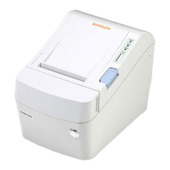
◈ Components
Cable Cover
SRP-370/372
AC/DC Adaptor
◈ Connecting the cables
1. Turn off the printer and the host ECR (host computer).
2. Plug the power cord into the Adaptor, and then plug the Adaptor into the power connector
of the printer.
3. Check the interface cable (Serial, Parallel, USB, or Ethernet), and connect the interface
connector cable accordingly.
4. Plug the drawer kick-out cable into the drawer kick-out connector on the printer.
※ Do not use an adapter that was not supplied with the printer.
Drawer kick-out connector
Power connector
Adaptor
Power cord
◈ Installing the Paper Roll
※ Note : Adjusting the Paper Near-End Sensor
The paper near-end sensor performs the two functions of gauging
'No Paper' status as well as detecting black marks. In order to
gauge 'No Paper' status, the sensor must be in the "a" position as
shown in the picture. The factory default setting places the
sensor in this position. To detect black marks, the sensor must
be in the "b" position.
Black marks must have an optical density (O.D.) of at least 0.6 to
be safely detected.
As the black mark density of the paper can cause operating
errors, make sure to check it.
※ Note: O.D. Value Chart
Paper Roll
Power cord
Installation Guide
Drawer
Interface cable
(Serial/Parallel/USB/Ethernet
kick-out
cable
1. Open the paper roll cover by
pressing the cover-open button.
2. Insert a new paper roll, making
sure to align it properly.
3. Pull out a small amount of paper,
and close the cover.
※ Note
When closing the cover, press down
on the center of the cover to ensure
that the paper is in contact with the
roller.
Printing quality may not be optimum
if recommended paper is not used.
(Refer to the User's Manual.)
1.4
0.9
0.6
0.3
0.2
Printer Installation Guide
THERMAL PRINTER
◈ Using the Operation Panel
Procuct Installation CD
Procuct Installation CD
Procuct Installation CD
CD
◈ Setting the DIP switches
Changing Dip Switch settings must be done when the printer is off. Any changes done while
the printer is on will not be processed.
1. Serial Interface
• DIP Switch 1
SW
1-1
1-2
1-3
1-4
1-5
1-6
1-7
1-8
• DIP Switch 2
SW
2-1
2-2
2-3
2-4
2-5
2-6
2-7
Near End Sensor Status
Interface
2-8
connector
2. Parallel / USB Interface
• DIP Switch 2
SW
2-1
2-2
2-3
2-4
2-5
2-6
2-7
Near End Sensor Status
2-8
• Table1 – Baud rate (bps) Selection
1-1
OFF
ON
OFF
ON
• Table 2 – Print Density Selection
2-1
ON
OFF
ON
OFF
OFF
ON
OFF
ON
SRP-370/372
• POWER (LED)
When turning on the power, a green LED will be lit.
• ERROR (LED)
When an error occurs, a red LED will be lit.
(e.g. no paper, cover ajar, etc.)
• PAPER (LED)
Red LED will be lit when the paper roll is running low. The LED blinks
when the printer is in self-test printing standby mode or macro execution
standby mode.
• FEED (Button)
Press the FEED button once to discharge extra paper. Holding down the
FEED button will discharge paper continuously until the button is
released.
Function
ON
Baud Rate Selection
Refer to the following table 1
Software
Handshaking
(Xon/Xoff)
Reserved
Auto Cutter
Disable
Paper
Two colors
Reserved
Reserved
Function
ON
Print Density
Refer to the following table 2
Historical Control
Enable
Reserved
Interface Condition
Memory
Selection
Switch
Disable
Printing Width
2" Printing
Function
ON
Print Density
Refer to the following table 2
Historical Control
Enable
Reserved
Interface Condition
Memory
Selection
Switch
Disable
Printing Width
2" Printing
1-2
Transmission Speed
OFF
OFF
ON
ON
2-2
2-3
ON
ON
ON
ON
OFF
ON
OFF
ON
OFF
OFF
OFF
OFF
ON
OFF
ON
OFF
Ver.2
OFF
Default
ON
ON
Hardware
OFF
(DTR/DSR)
--
OFF
Enable
OFF
Mono color
OFF
--
OFF
--
ON
OFF
Default
OFF
OFF
OFF
Disable
OFF
--
OFF
DIP Switch
OFF
Enable
OFF
3" Printing
OFF
OFF
Default
OFF
OFF
OFF
Disable
OFF
--
OFF
DIP Switch
OFF
Enable
OFF
3" Printing
OFF
Default
9600
19200
115200
38400
115200
Print Density
Default
130%
120%
110%
105%
100%
100%
95%
90%
80%
Advertisement
Table of Contents

Subscribe to Our Youtube Channel
Related Manuals for BIXOLON SRP-370


Summary of Contents for BIXOLON SRP-370
- Page 1 3. Utilities: a logo download tool and a virtual memory switch control tool (e.g. no paper, cover ajar, etc.) We at BIXOLON maintain ongoing efforts to enhance and upgrade the functions and quality • PAPER (LED) of all our products. In following, product specifications and/or user manual content may be Red LED will be lit when the paper roll is running low.
- Page 2 5. In the Question window, select Yes and the computer will reboot. Characters per line 180 DPI 42 (Font A) 203 DPI 48 (Font A) 6. After rebooting, open Start > Settings > Printers & Fax > BIXOLON SRP-370 Icon > (default) 56 (Font B) 64 (Font B) Right-Click >...
- Page 3 • PAPER (VOYANT) Nous, BIXOLON, poursuivons sans cesse nos efforts afin d’améliorer et de mettre à jour les Lorsque le rouleau de papier est presque terminé, le voyant papier fonctions et la qualité de tous nos produits.
- Page 4 (IEEE1284) : IFA-P TYPE 1. Après avoir lancé le CD d’installation du produit, lancer le fichier imprimante thermique > SRP-370 > Pilotes > Pilote Windows > Fichier Pilotes > Win SRP-370_Vx.x.x.exe ◈ Caractéristiques 2. Dans la fenêtre de demande d’installation, cliquer sur Suivant.
- Page 5 • PAPER (LED) Se encenderá un LED rojo cuando el rollo de papel esté por terminarse. En BIXOLON mantenemos esfuerzos continuos para mejorar y actualizar las funciones y la El LED parpadea cuando la impresora está en modo de espera por calidad de todos nuestros productos.
- Page 6 (IEEE1284): IFA-P TYPE 1. Luego de ejecutar el CD de instalación del producto, ejecute el archivo Impresora ◈ Especificaciones térmica > SRP-370 > Controladores > Controladores de Windows > Carpeta de Controladores > Win SRP-370_Vx.x.x.exe. Elemento Detalles 2.
- Page 7 • PAPER (LED) Nós, na BIXOLON tentamos melhorar constantemente e actualizar as funções e qualidade O LED vermelho acende-se quando o rolo de papel estiver a correr dos nossos produtos. Deste modo, as especificações do produto e/ou o conteúdo do abaixo do nível normal.
- Page 8 ROM e as definições do interruptor DIP. fixa paralela (IEEE1284): IFA-P TYPE 1. Depois de executar o CD de instalação do produto, execute Thermal Printer > SRP-370 > Drivers > Windows Driver > Drivers Folder > Ficheiro Win SRP-370_Vx.x.x.exe.
Need help?
Do you have a question about the SRP-370 and is the answer not in the manual?
Questions and answers