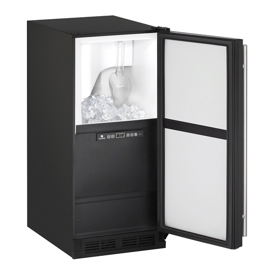
U-Line CLR1215 User Manual
15" clear ice maker
Hide thumbs
Also See for CLR1215:
- User manual & service manual (53 pages) ,
- User manual (39 pages) ,
- Quick start manual (17 pages)

Related Manuals for U-Line CLR1215


Summary of Contents for U-Line CLR1215
- Page 1 USER GUIDE SAFETY • INSTALLATION & INTEGRATION • OPERATING INSTRUCTIONS • MAINTENANCE • SERVICE RIGHT PRODUCT. RIGHT PLACE. RIGHT TEMPERATURE. SINCE 1962. 1000 Series CLR1215 15" Clear Ice Maker • •...
-
Page 2: Table Of Contents
USER GUIDE u-line.com SAFETY • INSTALLATION & INTEGRATION • OPERATING INSTRUCTIONS • MAINTENANCE • SERVICE Contents Maintenance Intro Cleaning Safety Cleaning Condenser Safety and Warning Extended Non-Use Disposal and Recycling Service Installation Troubleshooting Environmental Requirements Warranty Electrical Service Extended Cutout Dimensions... - Page 3 1. U-Line Customer Care must be contacted immediately at +1.800.779.2547. 2. Service or repairs performed on the unit without prior written approval from U-Line is not permitted. If the unit has been altered or repaired in the field without prior written approval from U-Line, claims will not be eligible.
-
Page 4: Safety And Warning
USER GUIDE u-line.com SAFETY • INSTALLATION & INTEGRATION • OPERATING INSTRUCTIONS • MAINTENANCE • SERVICE Safety and Warning NOTICE Please read all instructions before installing, operating, or servicing the appliance. Use this appliance for its intended purpose only and follow... -
Page 5: Disposal And Recycling
USER GUIDE u-line.com SAFETY • INSTALLATION & INTEGRATION • OPERATING INSTRUCTIONS • MAINTENANCE • SERVICE Disposal and Recycling DANGER RISK OF CHILD ENTRAPMENT. Before you throw away your old refrigerator or freezer, take off the doors and leave shelves in place so children may not easily climb inside. -
Page 6: Environmental Requirements
USER GUIDE u-line.com SAFETY • INSTALLATION & INTEGRATION • OPERATING INSTRUCTIONS • MAINTENANCE • SERVICE Environmental Requirements This model is intended for indoor/interior applications only and is not to be used in installations that are open/ exposed to natural elements. -
Page 7: Electrical
USER GUIDE u-line.com SAFETY • INSTALLATION & INTEGRATION • OPERATING INSTRUCTIONS • MAINTENANCE • SERVICE Electrical WARNING SHOCK HAZARD — Electrical Grounding Required. Never attempt to repair or perform maintenance on the unit until the electricity has been disconnected. Never remove the round grounding prong from the plug and never use a two-prong grounding adapter. -
Page 8: Cutout Dimensions
SAFETY • INSTALLATION & INTEGRATION • OPERATING INSTRUCTIONS • MAINTENANCE • SERVICE Cutout Dimensions PREPARE SITE Your U-Line product has been designed for either free- standing or built-in installation. When built-in, your unit does not require additional air space for top, sides, or rear. -
Page 9: Product Dimensions
USER GUIDE u-line.com SAFETY • INSTALLATION & INTEGRATION • OPERATING INSTRUCTIONS • MAINTENANCE • SERVICE Product Dimensions 23-1/4" (591 mm) (Includes 3/4" [20 mm] Integrated Panel) 34-1/8" to 35-1/8" (867 mm to 892 mm) 3-9/16" (91 mm) 14-15/16" (379 mm) -
Page 10: Side By Side Installation
USER GUIDE u-line.com SAFETY • INSTALLATION & INTEGRATION • OPERATING INSTRUCTIONS • MAINTENANCE • SERVICE Side-by-Side Installation 3. Place bracket over holes and attach to unit with two screws removed in step 2 using a T-25 Torx driver. Two units may be installed side-by-side. -
Page 11: Water Hookup
USER GUIDE u-line.com SAFETY • INSTALLATION & INTEGRATION • OPERATING INSTRUCTIONS • MAINTENANCE • SERVICE Water Hookup CAUTION PREPARE PLUMBING Do not use any plastic water supply line. The line Please use the braided stainless steel water supply line is under pressure at all times. Plastic may crack which comes attached. - Page 12 USER GUIDE u-line.com SAFETY • INSTALLATION & INTEGRATION • OPERATING INSTRUCTIONS • MAINTENANCE • SERVICE 4. Turn on water and check for leaks. 5. Route water supply line in cable clamp and secure with screw. Water Hookup 2...
-
Page 13: Drain
DRAIN CONNECTION CAUTION With Trap and Vent Proper Drain If your U-Line unit did not come with a factory installed drain pump you must use a gravity A gravity drain may be used if: style drain connection. For assistance in Drain line has at least a 1"... - Page 14 (Optional Hook-Up) requirements for a gravity drain, you may have ordered a pre-installed U-Line P60 drain pump. Waste If you need to install a P60 drain pump into your unit, see Valve DRAIN PUMP section in the User Manual.
-
Page 15: Drain Pump
Ice Machine ships with before installing the unit. discharge tube installed.) • The U-Line P60-00 drain pump is designed to be used 5. 2x Vent tube Zip Ties exclusively on the U-Line Clear Ice Machine and is UL recognized only for use on the U-Line Clear Ice 6. - Page 16 USER GUIDE u-line.com SAFETY • INSTALLATION & INTEGRATION • OPERATING INSTRUCTIONS • MAINTENANCE • SERVICE Note: Slide clamp on hose end before installing hose. Do not tighten clamp until pump and hoses have been installed. 6. Install the 3 hoses and hose...
- Page 17 USER GUIDE u-line.com SAFETY • INSTALLATION & INTEGRATION • OPERATING INSTRUCTIONS • MAINTENANCE • SERVICE WARNING The back panel serves as a guard. Do not put your hands inside the ice machine cabinet or attempt to touch any components except the discharge tube during testing.
-
Page 18: Anti-Tip Bracket
USER GUIDE u-line.com SAFETY • INSTALLATION & INTEGRATION • OPERATING INSTRUCTIONS • MAINTENANCE • SERVICE Anti-Tip Bracket 1. Slide unit out so screws on top of unit are easily accessible. 2. Remove the two screws from the opposite side of the hinge assembly using a T-25 Torx driver (see below). -
Page 19: General Installation
USER GUIDE u-line.com SAFETY • INSTALLATION & INTEGRATION • OPERATING INSTRUCTIONS • MAINTENANCE • SERVICE General Installation INSTALLATION 1. Plug in the power/electrical cord. LEVELING INFORMATION 1. Use a level to 2. Gently push the unit into position. Be careful not to confirm the unit is entangle the cord or water and drain lines. -
Page 20: Integrated Panel Dimensions
USER GUIDE u-line.com SAFETY • INSTALLATION & INTEGRATION • OPERATING INSTRUCTIONS • MAINTENANCE • SERVICE Integrated Panel Dimensions Integrated Panel Dimensions INTEGRATED PANEL BACK SURFACE MUST HAVE AMPLE FLAT SURFACE TO MOUNT OVERLAY PANEL FLAT AND WITHOUT 3/4" INTERFERENCE (20 mm) NOTICE 14-3/4"... -
Page 21: Integrated Panel Installation
Integrated Panel Installation 6. Secure integrated panel to door/drawer Clamp 1. Fully open door/drawer. using clamps. A robust tape may also be used. U-Line 2. Starting at corner, pull recommends the use gasket away from door/ of bar clamps to drawer. Door/Drawer secure the panel to the door/drawer. - Page 22 USER GUIDE u-line.com SAFETY • INSTALLATION & INTEGRATION • OPERATING INSTRUCTIONS • MAINTENANCE • SERVICE 11.Remove clamps from door/drawer. NOTICE If panel requires additional adjustment after removing clamps, slightly loosen each screw and adjust panel as necessary. Tighten screws upon completion.
-
Page 23: Grille / Plinth Installation
USER GUIDE u-line.com SAFETY • INSTALLATION & INTEGRATION • OPERATING INSTRUCTIONS • MAINTENANCE • SERVICE Grille - Plinth Installation REMOVING AND INSTALLING GRILLE WARNING Disconnect electric power to the unit before removing the grille. When using the unit, the grille (plinth strip/base fascia) must be installed. -
Page 24: Door Swing
USER GUIDE u-line.com SAFETY • INSTALLATION & INTEGRATION • OPERATING INSTRUCTIONS • MAINTENANCE • SERVICE Door Swing Wall Wall 1/4" Min. 2-1/8" Min. (6 mm) (54 mm) Door Swing Door Swing Units have a zero clearance for the door to open 90°, when installed adjacent to cabinets. -
Page 25: Door Stop
3. On 24" models, a second pin is included for the bottom hinge. Repeat steps above for second hinge. Your U-Line unit was shipped to you with the optional 90° pin(s). (Models that are 15" wide include 1 pin. Models NOTE: Threaded pin will be inserted from the bottom. -
Page 26: Door Adjust
USER GUIDE u-line.com SAFETY • INSTALLATION & INTEGRATION • OPERATING INSTRUCTIONS • MAINTENANCE • SERVICE Door Adjustments DOOR ALIGNMENT AND ADJUSTMENT Align and adjust the door if it is not level or is not sealing properly. If the door is not sealed, the unit may not cool properly, or excessive frost may form in the interior. - Page 27 USER GUIDE u-line.com SAFETY • INSTALLATION & INTEGRATION • OPERATING INSTRUCTIONS • MAINTENANCE • SERVICE Remove bottom hinge: Prepare door for reinstallation: 1. Remove bottom hinge from cabinet. 1. Rotate door 180° to reverse. 2. Remove gasket center strip and apply in-line with new opening (approximately 2"...
-
Page 28: First Use
USER GUIDE u-line.com SAFETY • INSTALLATION & INTEGRATION • OPERATING INSTRUCTIONS • MAINTENANCE • SERVICE First Use All U-Line controls are preset at the factory. Initial startup requires no adjustments. NOTICE U-Line recommends discarding the ice produced during the first two to three hours of operation to avoid possible dirt or scale that may dislodge from the water line. -
Page 29: Control Operation
USER GUIDE u-line.com SAFETY • INSTALLATION & INTEGRATION • OPERATING INSTRUCTIONS • MAINTENANCE • SERVICE Control Operation Alert Up Down Light Power Clean CONTROL FUNCTION GUIDE FUNCTION COMMAND DISPLAY/OPTIONS ON/OFF Press and release Unit will immediately turn ON or OFF. -
Page 30: Ice
USER GUIDE u-line.com SAFETY • INSTALLATION & INTEGRATION • OPERATING INSTRUCTIONS • MAINTENANCE • SERVICE Cube Types ICE CUBE THICKNESS ADJUSTMENT 1/4" TO 1/2" 1/16" TO 1/8" Interval - As Required (6.4 mm to 12.7 mm) (1.6 mm to 3.2 mm) -
Page 31: Sabbath Mode
Sabbath Mode Select Down U-Line Clear Ice Machine models are Star-K certified and can be used during the Sabbath. View a full list of Star-K certified U-Line units at www.star-k.org. To prepare the unit for the Sabbath: 1. Press and hold the until the unit turns off. -
Page 32: Airflow And Product Loading
USER GUIDE u-line.com SAFETY • INSTALLATION & INTEGRATION • OPERATING INSTRUCTIONS • MAINTENANCE • SERVICE Airflow and Product Loading NOTICE The unit requires proper airflow to perform at its highest efficiency. Do not block the front grille at any time, or the unit will not perform as expected. -
Page 33: Cleaning
For best results use Claire Stainless Steel Rinse the interior using a soft sponge and clean water. Polish and Cleaner, which can be purchased from U-Line Corporation (Part Number 173348). Comparable products are acceptable. Frequent cleaning will remove surface Do not use any solvent-based or abrasive contamination that could lead to rust. - Page 34 Water trough before use. 6. Clean the Interior Bin as follows: U-Line Ice Machine Cleaner is used to remove lime scale and other mineral deposits. Refer to the following steps to initiate the self-cleaning cycle. • Dilute one packet of CLR cleaner into two quarts of water.
- Page 35 Due to variations in water quality or inadequate maintenance your unit may become excessively coated in lime scale or calcium. U-Line offers a cost effective refresh kit which replaces many interior components and will return your unit to like new condition. Refresh kits may be ordered from your local distributor and installed by your local service company.
-
Page 36: Cleaning Condenser
USER GUIDE u-line.com SAFETY • INSTALLATION & INTEGRATION • OPERATING INSTRUCTIONS • MAINTENANCE • SERVICE Cleaning Condenser INTERVAL - EVERY SIX MONTHS To maintain operational efficiency, keep the front grille free of dust and lint, and clean the condenser when necessary. -
Page 37: Extended Non-Use
SAFETY • INSTALLATION & INTEGRATION • OPERATING INSTRUCTIONS • MAINTENANCE • SERVICE Extended Non-Use VACATION/HOLIDAY, PROLONGED SHUTDOWN For questions regarding winterization, please call U-Line at +1.800.779.2547. The following steps are recommended for periods of extended non-use: CAUTION 1. Remove all consumable content from the unit. -
Page 38: Troubleshooting
• Evaporator: Refrigerant flowing through an evaporator may sound like boiling liquid. BEFORE CALLING FOR SERVICE If you think your U-Line product is malfunctioning, read • Condenser Fan: Air moving through a condenser may the CONTROL OPERATION section to clearly understand be heard. -
Page 39: Warranty
God, such as fire, floods, wind, and U-Line product to be free from defects in materials and lightning; damages incurred or resulting from shipping, workmanship for a period of five years from the date of improper installation, unauthorized modification, or purchase. - Page 40 7. If a product defect is discovered during the applicable warranty period, you must promptly notify either U-Line at 8900 N. 55th Street, Milwaukee, Wisconsin 53223 USA or at +1.800.779.2547 or the dealer from whom you purchased the product. In no event shall such notification be received later than 30 days after the expiration of the applicable warranty period.
-
Page 41: Wire Diagram
USER GUIDE u-line.com SAFETY • INSTALLATION & INTEGRATION • OPERATING INSTRUCTIONS • MAINTENANCE • SERVICE Wire Diagram Wire Diagram 1... -
Page 42: Product Liability
U-Line in an unaltered condition. The dealer would then be authorized to • When the unit is ready for pickup, contact U-Line at permanently replace the end-user’s product at no cost to +1.800.779.2547 and U-Line will make arrangements the end-user. -
Page 43: Warranty Claims
USER GUIDE u-line.com SAFETY • INSTALLATION & INTEGRATION • OPERATING INSTRUCTIONS • MAINTENANCE • SERVICE Warranty Claims warranty status. We also accept the following information to verify warranty status: The following information defines the parameters for filing a warranty claim: •... -
Page 44: Ordering Replacement Parts
Warranty parts will be shipped at no charge after U-Line confirms warranty status. Please provide the model, serial number, part number and part description. Some parts will require color or voltage information. -
Page 45: System Diagnosis Guide
USER GUIDE u-line.com SAFETY • INSTALLATION & INTEGRATION • OPERATING INSTRUCTIONS • MAINTENANCE • SERVICE System Diagnosis Guide REFRIGERATION SYSTEM DIAGNOSIS GUIDE System Suction Suction Compressor Condenser Capillary Evaporator Wattage Condition Pressure Line Discharge Tube Normal Normal Slightly below Very hot... -
Page 46: Compressor Specifications
USER GUIDE u-line.com SAFETY • INSTALLATION & INTEGRATION • OPERATING INSTRUCTIONS • MAINTENANCE • SERVICE Compressor Specifications DANGER OVERLOAD PROTECTOR Electrocution can cause death or serious injury. Burns from hot or cold surfaces can cause serious injury. Take precautions when servicing this unit. -
Page 47: Troubleshooting Extended
DC outputs located on the relay/power board. Included in this section are some diagnostic tips and of course, if additional help is required please contact the U-Line Corp, “Customer Care Facility” at +1.800.779.2547 for assistance. Troubleshooting - Extended 1... - Page 48 Go to component testing and turn off fill valve, level unit if needed. Low Ice Dirty evaporator, dirty condenser, faulty bin Clean the evaporator using U-Line cleaner, clean the condenser coil if Production thermistor needed, check bin thermistor reading in service mode.
- Page 49 USER GUIDE u-line.com SAFETY • INSTALLATION & INTEGRATION • OPERATING INSTRUCTIONS • MAINTENANCE • SERVICE REFRIGERATION SYSTEM DIAGNOSIS GUIDE System Suction Suction Compressor Condenser Capillary Evaporator Wattage Condition Pressure Line Discharge Tube Normal Normal Slightly below Very hot Very hot...
- Page 50 USER GUIDE u-line.com SAFETY • INSTALLATION & INTEGRATION • OPERATING INSTRUCTIONS • MAINTENANCE • SERVICE NOTICE Check Voltage Alert Customer No Voltage Frequently toggling the compressor relay could At Wall Outlet Of Power Failure force the compressor into overload. The...
- Page 51 USER GUIDE u-line.com SAFETY • INSTALLATION & INTEGRATION • OPERATING INSTRUCTIONS • MAINTENANCE • SERVICE THERMISTOR FAILURE Always assure that all thermistor connections are clean and dry. Whenever opening a thermistor connection be sure to apply a fresh dab of die electric grease.
- Page 52 USER GUIDE u-line.com SAFETY • INSTALLATION & INTEGRATION • OPERATING INSTRUCTIONS • MAINTENANCE • SERVICE Control Operation - Service UI BUTTON LAYOUT Hidden Button -Accesses Service Menu -No LED Up Button -Increases temperature -Navigates through service menu Down Button -Decreases temperature...
-
Page 53: Control Quick Guide
USER GUIDE u-line.com SAFETY • INSTALLATION & INTEGRATION • OPERATING INSTRUCTIONS • MAINTENANCE • SERVICE CONTROL QUICK GUIDE CONTROL FUNCTION GUIDE FUNCTION COMMAND DISPLAY/OPTIONS ON/OFF Push and release the power key to power the unit ON or OFF View bin thermistor set... - Page 54 USER GUIDE u-line.com SAFETY • INSTALLATION & INTEGRATION • OPERATING INSTRUCTIONS • MAINTENANCE • SERVICE SILENT MODE In some cases it may be requested for the unit to be shut down for short periods during meetings for example. To do this hold the down arrow and press the up arrow three times.
- Page 55 USER GUIDE u-line.com SAFETY • INSTALLATION & INTEGRATION • OPERATING INSTRUCTIONS • MAINTENANCE • SERVICE Service Mode Quick Guide Number Service Mode Menu Item To Navigate/Access View thermistor #1 cabinet temp no offsets Use up/down to access and light bulb key to view...
- Page 56 USER GUIDE u-line.com SAFETY • INSTALLATION & INTEGRATION • OPERATING INSTRUCTIONS • MAINTENANCE • SERVICE SERVICE MODE QUICK GUIDE 13.Does not apply to this model. THERMISTOR 1 — TEMPERATURE This will show the pure thermistor reading with no ERROR LOG offsets taken into account.
- Page 57 2224R 2260R 1224RSOD 2224RG 2260RDC 1224WC 2224WC 2260WC CLR1215 2224ZWC 2260ZWC CO1224F ADA24R PROGRAMMING THE UNIT TO CORRECT MODEL NUMBER • Unplug unit and install new board • Use the up/down arrows to scroll to correct model number from chart •...
-
Page 58: Control Defaults
USER GUIDE u-line.com SAFETY • INSTALLATION & INTEGRATION • OPERATING INSTRUCTIONS • MAINTENANCE • SERVICE Control Defaults Default Value Fahrenheit/Celsius* °F °C Defrost Duration Minutes Next Defrost Hours Thermistor Four OFFSET** — Thermistor Three OFFSET** — Thermistor Two OFFSET** —... -
Page 59: Service Mode
USER GUIDE u-line.com SAFETY • INSTALLATION & INTEGRATION • OPERATING INSTRUCTIONS • MAINTENANCE • SERVICE Service Mode SERVICE MODE QUICK GUIDE Number Service Mode Menu Item To Navigate/Access VIEW THERMISTOR #1 CABINET TEMP NO OFFSETS USE UP/DOWN TO ACCESS AND LIGHT BULB KEY TO VIEW... - Page 60 USER GUIDE u-line.com SAFETY • INSTALLATION & INTEGRATION • OPERATING INSTRUCTIONS • MAINTENANCE • SERVICE ERRORS Programming the unit to correct model number *All errors are logged in memory. 1. Unplug unit and install new board *Only door error is displayed on the display and has an 2.
- Page 61 USER GUIDE u-line.com SAFETY • INSTALLATION & INTEGRATION • OPERATING INSTRUCTIONS • MAINTENANCE • SERVICE Thermistors Thermistor Resistance Data Nominal Resistance Temp (F) Temp (C) Thermistors are used for various temperature readings. (OHMS)* Thermistors provide reliable temperature readings using a...
-
Page 62: Defrost
USER GUIDE u-line.com SAFETY • INSTALLATION & INTEGRATION • OPERATING INSTRUCTIONS • MAINTENANCE • SERVICE Defrost These models have no defrost options. Defrost 1...