kozy heat 932 Installation & Operating Manual
Direct vent wall-furnace
Hide thumbs
Also See for 932:
- Installation & operating manual (31 pages) ,
- Installation and operating manual (33 pages) ,
- Installation and operating manual (32 pages)
Table of Contents
Advertisement
INSTALLATION & OPERATING MANUAL
MODELS:
#932 DIRECT VENT WALL-FURNACE
#936 DIRECT VENT WALL- FURNACE
U.S. Patents:
#5.931.154
#6.004.493
IMPORTANT:
READ INSTRUCTIONS CAREFULLY BEFORE INSTALLATION. FAILURE TO INSTALL
THIS FIREPLACE CORRECTLY CAN CAUSE SERIOUS STRUCTURAL AND FIRE
.
HAZARDS AND MAY VOID YOUR WARRANTY
www.kozyheat.com
July 2006
Page 1
Advertisement
Table of Contents

Subscribe to Our Youtube Channel
Related Manuals for kozy heat 932

Summary of Contents for kozy heat 932
- Page 1 INSTALLATION & OPERATING MANUAL MODELS: #932 DIRECT VENT WALL-FURNACE #936 DIRECT VENT WALL- FURNACE U.S. Patents: #5.931.154 #6.004.493 IMPORTANT: READ INSTRUCTIONS CAREFULLY BEFORE INSTALLATION. FAILURE TO INSTALL THIS FIREPLACE CORRECTLY CAN CAUSE SERIOUS STRUCTURAL AND FIRE HAZARDS AND MAY VOID YOUR WARRANTY www.kozyheat.com...
-
Page 2: Table Of Contents
MODEL #932 DV ........ -
Page 3: Installation Instructions
IMPORTANT: READ THIS MANUAL BEFORE INSTALLING AND USING THIS FIREPLACE MODELS #932 DV & #936 DV WALL FURNACE INSTALLATION INSTRUCTIONS This appliance has been tested to and complies with ANSI Z21.88-2002•CSA 2.33-M02, “VENTED GAS FIREPLACE HEATER”. Installation must conform with local building codes, or, in the absence of local building codes, with the national fuel gas code, ANSI Z223.1, NFPA 54 - current edition, or the Manufactured Home Construction and Safety Standard, Title 24 CFR, Part 3288. -
Page 4: Gas Conversion Kit
If a gas conversion is necessary, one of the following conversions kits must be used: Natural Gas Converison Kits - used to convert an LP millivolt board to natural gas. Model #932 - #OCK-S38 Model #936 - #OCK-H31N LP Gas Conversion Kits - used to convert a Natural Gas millivolt board to LP Gas. -
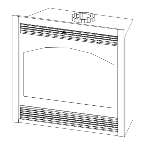
Page 5: Determine Location
A) PREPARE THE FIREPLACE Figure 2 1. REMOVE THE GLASS ASSEMBLY. See Figure 2. A. Locate the spring-loaded latch handles securing the glass assembly (under the firebox). B. Pull the handles out, then down to release the glass assembly. C. Pull the bottom of the glass assembly out and lift up off the tabs (at the top). - Page 6 Figure 3A 36 1 2 Figure 3B 18 1 2 13 3 44 13 MODEL 936 63 3 NOTE: * = 1/4" CLEARANCE ALL DIMENSIONS ARE MINIMUM 18 1/2" Page 6...
- Page 7 The minimum for the support platform under the unit is: Model #932 DV: 18 1/4” deep by 32” wide Model #936 DV: 18 1/4" deep by 36" wide. If masonry is to be used (optional), prepare the necessary foundation for the masonry load.
-
Page 8: Venting Requirements
- #745 KOZY HEAT DIRECT VENT KIT - For terminations of 4' or less. - #718 KOZY HEAT DIRECT VENT KIT - For terminations greater than 4' but less than 8'. - #746 KOZY HEAT DIRECT VENT EXTENSION KIT - Used to extend the #745 or #718 kit an additional 6'. - Page 9 RESTRICTOR INSTALLATION The restrictor plate included in the fireplace components packet can be installed as either a large or small restrictor, depending on your specific venting configuration. There are several factors which can affect proper draft of the vent system and the burner operation of a fireplace. Installing a restrictor may be necessary to resolve the Figure 6A problem, even though it may not be required under ‘normal...
- Page 10 TERMINATION VENT CAP LOCATION: This gas appliance must not be connected to a chimney flue serving another type of appliance. GENERAL: Terminations against vinyl siding must use a vinyl siding protector. Follow instructions included. DO NOT RECESS TERMINATION KIT INTO OUTSIDE BUILDING MATERIALS - i.e.: brick, stone, etc.. If necessary, extend framing so that termination kit will be exposed once building materials are installed.
-
Page 11: Venting Requirements
HORIZONTAL VENTING REQUIREMENTS MINIMUM VERTICAL RISE* FROM TOP OF UNIT: 18 IN. (to top of 7” pipe) MINIMUM HORIZONTAL RUN: 6 IN. MAXIMUM HORIZONTAL RUN: 20 FT. (Horizontal runs must maintain 1/4” rise per ft.) TOTAL HORIZONTAL & VERTICAL RUN MUST NOT EXCEED 32 FT. *Minimum vertical rise directly off the top of the unit is determined by the length of the horizontal run. - Page 12 INSTALLATION OF THE #700 SERIES HORIZONTAL DIRECT VENT TERMINATION KIT(S). NOTE : #700 Series vent kits must be supported every 3 ft. to maintain proper rise. The flex pipe is permanently attached to the exterior wall plate. Do not attach the #745 or #718 termination kit to the fireplace (or extension kit) until it has passed through the wall.
-
Page 13: Fan Installation
A receptacle speed control assembly and (3) wire nuts are included in the fireplace components packet. This optional fan kit #932-028 (Model #932 DV) or #600-1* (Model #936 DV) includes: 1. Right and left fan assemblies with magnetic limit switch already mounted. - Page 14 INSTALLATION INSTRUCTIONS. REFER TO THE FIGURE BELOW. Remove the lower grill, if installed. OPTIONAL: For easier installation, the fans may be separated by unplugging the three-prong plug from the receptacle in the right fan assembly. Slide the left fan (A) (without receptacle) through the lower grill opening (right side of the valve) and place over the (2) left mounting studs (B) located towards the back of the fireplace.
- Page 15 The maximum inlet gas supply pressure: 13.0 inches W.C. Manifold Pressure: 10.0 inches W.C. Manifold Pressure (lo setting): 6.5 inches W.C. Model #932 - Orifice size: 53 Input: 26, 000 BTU’s Efficiency: 73% AFUE: 66.7% Model #936 - Orifice size: 51 Input: 35,000 BTU'S...
- Page 16 The left pressure tap is the manifold pressure and the right pressure tap is the incoming pressure. Follow instructions on page #26 for Model #932 DV and page #29 for Model #936 DV for checking these pressures. SECURE THE MILLIVOLT BOARD. See Figures 12A - 12D.
- Page 17 Before securing the board into place make sure that all of the wires (attached under the board) are clear and unobstructed. Attach the 1/4" nuts (included with the board assembly) and tighten. MODEL #932 DV: Replace the burner cover assembly, properly seating PILOT SHIELD the burner tube over the orifice. The burner cover should be ‘inside’ the flanges on the board.
-
Page 18: Log Installation
G) #932 DV LOG INSTALLATION. See Figures 13A - 13C This #932-500A log set includes: (1) ‘AD’ log (1) ‘BI’ log (1) ‘AJ’ log (1) ‘AG’ log (2) ‘M’ logs (1) ‘C’ log (1) ‘HB’ log (1) Rock wood embers pkt. -
Page 19: Log Installation
#936 DV LOG INSTALLATION. See Figures 13D -13F. This #936-50E log set includes: (1) X1 Log (1) X6 Log (1) X9 Log *Note: X5 Log is not (1) X2 Log (1) X7 Log (1) X10 Log used in this log set & has (1) X3 Log (1) X8 Log (1) Klinker pkg. - Page 20 MODEL #932 DV: THERMOSTAT, WALL SWITCH OR REMOTE CONTROL INSTALLATION CAUTION: DO NOT CONNECT HIGH VOLTAGE (115V) TO ANY OF THESE SYSTEMS. Figure 14A If desired, a thermostat, wall switch, or remote control assembly may be used to turn the fireplace ‘OFF’ and ‘ON’.
- Page 21 MODEL #936 DV THERMOSTAT - WALL SWITCH - REMOTE INSTALLATION (OPTIONAL). CAUTION: DO NOT CONNECT HIGH VOLTAGE (115V) WIRE TO THE GAS VALVE! NOTE: INSTALLATION OF A THERMOSTAT OR WALL SWITCH SHOULD ONLY BE DONE BY A QUALIFIED INSTALLER. If desired, a thermostat (wireless style available), wall switch, or remote control assembly may be used to turn Figure 14C the fireplace ‘OFF’...
- Page 22 THIS STEP SHOULD ONLY BE DONE BY A QUALIFIED INSTALLER OR SERVICE TECHNICIAN: A. Perform lighting and shutdown procedures as described on page #24-#25 for model #932 DV and pages #27-#28 for model #936 DV. This should be done prior to replacing the glass so that any necessary adjustments can be made and proper operation verified.
- Page 23 REPLACE THE GLASS. Refer also to Figure 2, page #5. A) Align the slots in the top of the glass assembly over the tabs on the fireplace. B) Place the glass assembly so it is flush with the front of the fireplace front. C) Secure the assembly to the fireplace by pushing the two spring loaded handles (located under the firebox) back, locking them into position.
-
Page 24: Lighting & Shutdown / Pressure Testing
Model #932 DV LIGHTING AND SHUTDOWN / PRESSURE TESTING NOTE: Prior to lighting, check all fittings for leakage. This is accomplished by applying soapy water on all connections made. If there is any leakage, bubbles will appear at the point of connection. If bubbles occur, tighten the fittings until the bubbles no longer appear. - Page 25 TO TURN THE BURNER OFF: To turn the burner ‘OFF’, depress the ON/OFF rocker switch to ‘OFF’, flip ‘off’ the wall switch or adjust the setting on the thermostat or remote control. NOTE: The pilot will stay lit. TO TURN THE PILOT OFF: To turn off the pilot, push in and turn the control knob to the "OFF"...
- Page 26 PRESSURE TEST - MANIFOLD & INLET PRESSURE IMPORTANT NOTICE: A pressure check tap for both the manifold (outgoing) and inlet (incoming) pressure has been incorporated into the valve by S.I.T. Controls. The right pressure tap is the manifold pressure and the left pressure tap measures the incoming pressure.
- Page 27 Model #936 DV: LIGHTING AND SHUTDOWN PROCEDURES NOTE: Prior to lighting, check all fittings for leakage. This is accomplished by applying soapy water on all connections made. If there is any leakage, bubbles will appear at the point of connection. If bubbles occur, tighten the fittings until the bubbles no longer appear. IMPORTANT: TEST ALL CONNECTIONS WHETHER FIELD OR FACTORY MADE.
- Page 28 Turn gas control knob counterclockwise to the "ON" position. 10. The burner can now be turned ‘ON’ or lit by depressing the bottom of the ON/OFF rocker switch (C) located beside the valve OR by setting the thermostat or remote control to the desired setting. 11.
- Page 29 PRESSURE TEST - MANIFOLD & INLET PRESSURE IMPORTANT NOTICE: A pressure check tap for both the manifold (outgoing) and inlet (incoming) pressure has been incorporated into the valve by Honeywell. The right pressure tap is the manifold pressure and the left pressure tap measures the incoming pressure. Follow the instructions below for proper pressure testing procedures.
-
Page 30: Model #932 Dv
/ cover assembly, sliding it off the burner BE REQUIRED DUE TO EXCESSIVE LINT orifice. FROM CARPETING, BEDDING MATERIALS, Model #932 DV: Remove the burner / cover ETC. IT IS IMPERATIVE THAT CONTROL assembly, sliding it off the burner orifice. -
Page 31: Model #932 Dv
All of the working parts of this unit can be removed at one time. Before removing millivolt board, check for loose wires. PROBLEM CAUSE SOLUTION No spark when piezo Model #932: The nut which holds the piezo Tighten nut. is depressed. in place is loose. Model #936: Wire on back of piezo button Put wire back into place. -
Page 32: Model #936 Dv
PROBLEM CAUSE SOLUTION Burner won't light. Pilot not lit. Relight pilot. Regulator valve not turned “on”. Turn valve to "on". Rocker switch not turned “on”. Press bottom of switch. Rocker switch wire not connected. Check wiring diagram Figures 21 & 22 to ensure that all wires are secure. -
Page 33: Replacement Parts
936-043 Pilot Shield GLASS & GLASS GASKET LOG SETS & REFRACTORY 700-08T 12" x 27" Glass with gasket - Model #932 DV 932-500A Log Set - #932 DV 700-07T 17" x 30" Glass with gasket - Model #936 DV 936-50E... - Page 34 Page 34...
-
Page 35: Warranty Policy
LIFETIME WARRANTY IS EXTENDED AS FOLLOWS: Hussong Manufacturing warranties to the original purchaser that the firebox, heat exchanger, fiber logs, burner tube and glass of this Kozy Heat fireplace will not be defective in material or workmanship under normal use and service for as long as you own this product. If any of these components fail due to defects in material or workmanship under normal use and service, Hussong Manufacturing Co., Inc.
Need help?
Do you have a question about the 932 and is the answer not in the manual?
Questions and answers