Table of Contents
Advertisement
Warm Air Gas Furnace / Downflow Air Discharge
This is a safety alert symbol and should never be ignored. When you see this symbol on labels or in
manuals, be alert to the potential for personal injury or death.
As with any mechanical equipment, personal injury can
result from contact with sharp sheet metal edges. Be
careful when you handle this equipment.
Unit Dimensions .............................................................2
A95DF2E/95G2DFE Parts Arrangement ........................3
A95DF2E/95G2DFE Gas Furnace .................................4
Shipping and Packing List ..............................................4
.......................................................4
Use of Furnace as a Construction Heater ......................5
.....................................................................6
Combustion, Dilution, Ventilation Air...............................6
Setting Equipment ..........................................................9
........................................................................12
Duct System .................................................................12
Pipe and Fittings Specifications....................................12
Joint Cementing Procedure ..........................................14
Venting Practices..........................................................14
*P507206-01*
(P) 507206-01
507206-01
INSTALLATION INSTRUCTIONS
A95DF2E, 95G2DFE
Direct Vent & Non-Direct Vent
This manual must be left with the homeowner for future reference.
CAUTION
TABLE OF CONTENTS
Improper installation, adjustment, alteration, service
or maintenance can cause property damage, personal
injury or loss of life. Installation and service must
be performed by a licensed professional installer (or
equivalent), service agency or the gas supplier.
Vent Piping Guidelines .................................................16
Condensate Piping........................................................31
Gas Piping ....................................................................35
Electrical .......................................................................37
Unit Start Up .................................................................48
Gas Pressure Adjustment .............................................49
High Altitude Information ..............................................50
Other Unit Adjustments.................................................51
Blower Motor Performance ...........................................52
Service ........................................................................53
Planned Service ...........................................................55
Repair Parts List ...........................................................56
Start Up Checklist .........................................................57
Commonwealth of Massachusetts.......................59
A Lennox International, Inc. Company
Issue 1337
WARNING
Manufactured By
Allied Air Enterprises LLC
215 Metropolitan Drive
West Columbia, SC 29170
Page 1 of 59
Advertisement
Table of Contents

Related Manuals for Airease A95DF2E


Summary of Contents for Airease A95DF2E
-
Page 1: Table Of Contents
(or equivalent), service agency or the gas supplier. TABLE OF CONTENTS Unit Dimensions .............2 Vent Piping Guidelines ..........16 A95DF2E/95G2DFE Parts Arrangement ......3 Condensate Piping............31 A95DF2E/95G2DFE Gas Furnace .........4 Gas Piping ..............35 Shipping and Packing List ..........4 Electrical ...............37... -
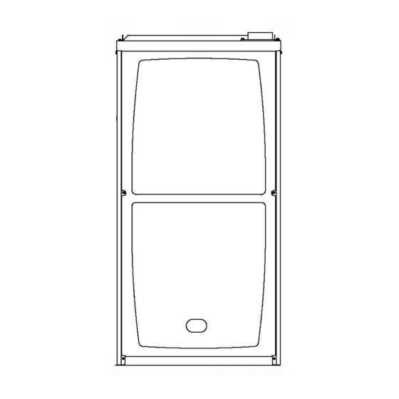
Page 2: Unit Dimensions
Unit Dimensions - inches (mm) Model A95UH2E/95G2UHE 045-12 17-1/2 16-3/8 070-16 090-20 19-7/8 19-1/2 110-20 Page 2 of 59 Issue 1337 507206-01... - Page 3 Figure 1 507206-01 Issue 1337 Page 3 of 59...
-
Page 4: Shipping And Packing List
Gas Furnace Shipping and Packing List This Category IV gas furnace is shipped ready for installation Package 1 of 1 contains: in the downflow position. 1 - Assembled Gas Unit 1 - Bag assembly containing the following: The furnace is equipped for installation in natural gas 1 - Snap bushing applications. -
Page 5: Use Of Furnace As A Construction Heater
In Canada, installation must conform with current National Standard of Canada CSA-B149 Natural Gas and Propane Installation Codes, local plumbing or waste water codes and other applicable local codes. In order to ensure proper unit operation in non-direct vent applications, combustion and ventilation air supply must be provided according to the current National Fuel Gas Code or CSA-B149 standard. -
Page 6: General
• Air filters must be replaced upon construction completion. • The input rate and temperature rise must be set per the WARNING furnace rating plate. • One hundred percent (100%) outdoor air must be provided The State of California has determined that this product for combustion air requirements during construction. - Page 7 air is brought into the house for combustion, negative infiltration. If the furnace is located in a building of tight pressure (outside pressure is greater than inside pressure) construction with weather stripping and caulking around will build to the point that a down draft can occur in the the windows and doors, follow the procedures in the “Air furnace vent pipe or chimney.
- Page 8 Air from Outside Equipment in Confined Space - All Air from Outside If air from outside is brought in for combustion and (All Air Through Ventilated Attic) ventilation, the confined space shall be provided with two permanent openings. One opening shall be within 12” (305 mm) of the top of the enclosure and one within 12”...
-
Page 9: Setting Equipment
Allow for clearances to combustible materials as indicated Equipment in Confined Space on the unit nameplate. Minimum clearances for closet or (Inlet Air from Ventilated Crawlspace & Outlet Air to Outside) alcove installations are shown in Figure 13. Units with 1/2 HP Blower Motor Figure 10 WARNING Blower access panel must be securely in place when... - Page 10 Installation on Non-Combustible Flooring WARNING 1. Cut floor opening keeping in mind clearances listed on unit rating plate. Also keep in mind gas supply Improper installation of the furnace can result in connections, electrical supply, flue and air intake personal injury or death. Combustion and flue products connections and sufficient installation and servicing must never be allowed to enter the return air system clearances.
- Page 11 Combustible Flooring Base Opening Size Table 2 Figure 16 Return Air Opening - Downflow Units Return air may be brought in only through the top opening of a furnace installed in the downflow position. The following steps should be taken when installing plenum: 1.
-
Page 12: Filters
Filters Pipe & Fittings Specifications This unit is not equipped with a filter or rack. A field provided All pipe, fittings, primer and solvent cement must conform filter is required for the unit to operate properly. Table 3 lists with American National Standard Institute and the American recommended filter sizes. - Page 13 vent pipe hangers. Uniformly apply a liberal coat of PVC primer for PVC or use a clean dry cloth for ABS to clean IMPORTANT inside socket surface of fitting and male end of pipe to depth of fitting socket. The exhaust and intake connections are made of PVC. Use PVC primer and solvent cement when using PVC Canadian Applications Only vent pipe.
-
Page 14: Joint Cementing Procedure
Joint Cementing Procedure Venting Practices All cementing of joints should be done according to the specifications outlined in ASTM D 2855. Piping Suspension Guidelines NOTE: A sheet metal screw may be used to secure the intake pipe to the connector, if desired. Use a drill or self tapping screw to make a pilot hole. - Page 15 1. Seal any unused openings in the common venting system. 2. Inspect the venting system for proper size and horizontal pitch. Determine that there is no blockage, restriction, leakage, corrosion, or other deficiencies which could cause an unsafe condition. 3. Close all building doors and windows and all doors between the space in which the appliances remaining connected to the common venting system are located and other spaces of the building.
-
Page 16: Vent Piping Guidelines
Terminations should be used. Exhaust vent termination pipe is sized to optimize the velocity of the exhaust gas as it exits the termination. MINIMUM VENT PIPE LENGTHS A95DF2E/95G2DFE MIN.VENT LENGTH* MODELS 045,070,090,110 15 ft or 5 ft plus 2 elbows or 10 ft plus 1 elbow *Any approved termination may be added to the minimm length listed. - Page 17 A95DF2E & 95G2DFE Table 7A 507206-01 Issue 1337 Page 17 of 59...
- Page 18 A95DF2E & 95G2DFE Table 7B Page 18 of 59 Issue 1337 507206-01...
- Page 19 A95DF2E & 95G2DFE Table 7C 507206-01 Issue 1337 Page 19 of 59...
- Page 20 Typical Exhaust Pipe Connections Figure 22 Typical Intake Pipe Connections (Direct Vent Applications) Figure 23 Page 20 of 59 Issue 1337 507206-01...
- Page 21 Intake Piping This furnace may be installed in either direct vent or non- direct vent applications. In non-direct vent applications, when intake air will be drawn into the furnace from the surrounding space, the indoor air quality must be considered. Guidelines listed in Combustion, Dilution and Ventilation Air section must be followed.
- Page 22 NOTE: See Table 8 for maximum allowed exhaust pipe IMPORTANT length without insulation in unconditioned space during winter design temperatures below 32° F (0° C). If required, Do not use screens or perforated metal in exhaust exhaust pipe should be insulated with 1/2” (13 mm), Armaflex terminations.
- Page 23 Vent Termination Clearances For Non-Direct Vent Installations in the USA and Canada Figure 26 507206-01 Issue 1337 Page 23 of 59...
- Page 24 Vent Termination Clearances For Direct Vent installations in the USA and Canada Figure 27 Page 24 of 59 Issue 1337 507206-01...
- Page 25 Details of Intake and Exhaust Piping Terminations for Direct Vent Roof Termination Kit Direct Vent Installations NOTE: In Direct Vent installations, combustion air is taken from outdoors and flue gases are discharged to outdoors. NOTE: Flue gas may be slightly acidic and may adversely affect some building materials.
- Page 26 Flush Mount Side Wall Termination Figure 31 6. On field supplied terminations, a minimum distance between the end of the exhaust pipe and the end of the intake pipe without a termination elbow is 8” and a minimum distance of 6” with a termination elbow. See Figures 33 and 34.
- Page 27 Figure 32 507206-01 Issue 1337 Page 27 of 59...
- Page 28 Field Supplied Wall Termination Field Supplied Wall Termination Figure 34 Figure 33 Page 28 of 59 Issue 1337 507206-01...
- Page 29 Direct Vent Concentric Rooftop Termination Optional Vent Termination for Multiple Unit Installation of Direct Vent Wall Termination Kit Figure 37 Figure 35 Direct Vent Application Using Existing Chimney Direct Vent Concentric Wall Termination Figure 36 Figure 38 507206-01 Issue 1337 Page 29 of 59...
- Page 30 Details of Exhaust Piping Terminations for Non-Direct Vent Applications Non-Direct Vent Field Supplied Wall Termination Exhaust pipe may be routed either horizontally through Extended an outside wall or vertically through the roof. In attic or closet installations, vertical termination through the roof is preferred.
-
Page 31: Condensate Piping
Condensate Piping Condensate Trap and Plug Locations This unit is designed for either right or left side exit of condensate piping in downflow applications. Refer to Figure 43 for condensate trap locations. NOTE: If necessary the condensate trap may be installed up to 5 feet away using PVC pipe from the furnace. - Page 32 NOTE: Vinyl tubing may be used for condensate drain. Condensate line must slope downward away from the trap Tubing must be 1-1/4” ODX1”ID and should be attached to drain. If drain level is above condensate trap, condensate to the drain on the trap using a hose clamp. pump must be used.
- Page 33 CAUTION When combining the furnace and evaporator coil drains together, the A/C condensate drain outlet must be vented to relieve pressure in order for the furnace pressure switch to operate properly. Ecaporator Coil Using a Common Drain Figure 46 Condensate Trap with Optional Overflow Switch Figure 47 507206-01 Issue 1337...
- Page 34 TRAP DRAIN ASSEMBLY USING 1/2” PVC or 3/4” PVC Figure 48 Page 34 of 59 Issue 1337 507206-01...
-
Page 35: Gas Piping
Gas Piping IMPORTANT Compounds used on threaded joints of gas piping must CAUTION be resistant to the actions of liquified petroleum gases. If a flexible gas connector is required or allowed by the authority that thas jurisdiction, black iron pipe shall be installed at the gas valve and extend outside the furnace Leak Check cabinet. - Page 36 Figure 50 Table 10 Page 36 of 59 Issue 1337 507206-01...
-
Page 37: Electrical
Electrical The unit is equipped with a field makeup box. The makeup ELECTROSTATIC DISCHARGE (ESD) box may be installed on the exterior of the right side of the Precautions and Procedures furnace to facilitate installation. Seal unused openings on left side with plugs removed from right side. Secure the excess wire to the existing harness to protect it from CAUTION damage. - Page 38 (“LOW HEAT” is default) when there is no cooling or heating demand. The line voltage supply should be routed through a readily 2 - When the A95DF2E or 95G2DFE is running in the accessible disconnect located within sight of the furnace. heating mode, A junction box on the furnace side panel is provided for line the indoor blower will run on the ‘LOW HEAT”...
- Page 39 Integrated Control DIP Switch Settings A95DF2E/95G2DFE units are equipped with a two-stage TABLE 12 integrated control. This control manages ignition timing, Blower Off Heating Mode Delay Switch Settings heating mode fan off delays and indoor blower speeds based on selections made using the control dip switches...
- Page 40 TYPICAL WIRING DIAGRAM Figure 54 Page 40 of 59 Issue 1337 507206-01...
- Page 41 3/16” QUICK CONNECT TERMINALS THERMOSTAT CONNECTIONS (TB1) FLAME SENSE SIGNAL DS = DEHUMIDIFICATION SIGNAL HI Cool 24VAC W2 = HEAT DEMAND FROM 2ND STAGE T/STAT HI HEAT 24VAC W1 = HEAT DEMAND FROM 1ST STAGE T/STAT LO COOL 24VAC R = CLASS 2 VOLTAGE TO THERMOG LO HEAT 24VAC G = MANUAL FSATNA FTROM C = THERMOSTT’ASTT ASTIGNAL GROUND CONNECTED TO...
- Page 42 Table 15 Field Wiring Applications With Conventional Thermostat Page 42 of 59 Issue 1337 507206-01...
- Page 43 Table 15 Field Wiring Applications With Conventional Thermostat (Continued) 507206-01 Issue 1337 Page 43 of 59...
- Page 44 Table 15 Field Wiring Applications With Conventional Thermostat (Continued) * Connect W1 to W1 ONLY if using defrost tempering kit 67M41 NOTE - Do NOT make a wire connection between the room thermostat L terminal and the L terminal of the integrated control.
- Page 45 Table 15 Field Wiring Applications With Conventional Thermostat (Continued) * Connect W1 to W1 ONLY if using defrost tempering kit 67M41 NOTE - Do NOT make a wire connection between the room thermostat L terminal and the L terminal of the integrated control.
- Page 46 Testing for Proper Venting and Sufficient Combustion Air for Non-Direct Vent Applications 6. Follow the lighting instruction to place the appliance being inspected into operation. Adjust thermostat so WARNING appliance will operate continuously. 7. Use the flame of a match or candle to test for spillage CARBON MONOXIDE POISONING HAZARD of flue gases at the draft hood relief opening after 5 Failure to follow the steps outlined below for each...
-
Page 47: Unit Start Up
Unit Start-Up Priming Condensate Trap The condensate trap should be primed with water prior to FOR YOUR SAFETY READ BEFORE OPERATING start-up to ensure proper condensate drainage. Either pour 10 fl. oz. (300 ml) of water into the trap, or follow these steps to prime the trap: 1. -
Page 48: Gas Pressure Adjustment
Gas Pressure Adjustment Gas Valve Shown In “ON’ Position Gas Flow (Approximate) GAS METER CLOCKING CHART Seconds for One Revolution Model Natural 1 cu ft Dial 2 cu ft Dial 1 cu ft Dial 2 cu ft Dial Natural - 1000 btu/cu ft LP- 2500 btu/cu ft Table 16 Figure 56... -
Page 49: High Altitude Information
Manifold and Supply Line Pressures Altitudes High Altitude Information NOTE: In Canada, certification for installations at elevations Manifold Pressure in w.g. Supply Line Pressure in w.g. A95DF2E over 4500 feet (1372 m) is the jurisdiction of local authorities. 95G2DFE Low Fire Hihh Fire Min. -
Page 50: Other Unit Adjustments
Other Unit Adjustments Thermostat Heat Anticipation Set the heat anticipator setting (if adjustable) according to Primary Limit the amp draw listed on the wiring diagram that is attached The primary limit is located on the heating compartment to the unit. vestibule panel. - Page 51 BLOWER DATA - Table 20 95DF045 PERFORMANCE (Less Filter) External Air Volume / Watts at Various Blower Speeds Static High Medium-High Medium Medium-Low Pressure Watts Watts Watts Watts Watts in. w.g. 0.00 1395 1290 1190 0.10 1375 1245 1140 0.20 1320 1215 1090...
-
Page 52: Service
Service Electrical 1. Check all wiring for loose connections. 2. Check for the correct voltage at the furnace (furnace WARNING operating). Correct voltage is 120 VAC ± 10%. 3. Check amp-draw on the blower motor with the blower ELECTRICAL SHOCK, FIRE, compartment access panel in place. - Page 53 16. Remove screws along vestibule sides and bottom which Cleaning the Burner Assembly secure vestibule panel and heat exchanger assembly 1. Turn off electrical and gas power supplies to furnace. to cabinet. Remove two screws from blower rail which Remove upper and lower furnace access panels. secure bottom heat exchanger flange.
-
Page 54: Planned Service
Planned Service A service technician should check the following items during an annual inspection. Power to the unit must be shut off for safety. Fresh air grilles and louvers (on the unit and in the room where the furnace is installed) - Must be open and unobstructed to provide combustion air. -
Page 55: Repair Parts List
REPAIR PARTS LIST The following repair parts are available through Allied Air dealers. When ordering parts, include the complete furnace model number listed on the CSA nameplate. Example: A95DF2V045B12S-01. All service must be performed by a licensed professional installer (or equivalent), service agency, or gas supplier. Cabinet Parts Heating Parts Heating Compartment Access Panel... - Page 56 Start-UP & Performance Check List Page 56 of 59 Issue 1337 507206-01...
- Page 57 UNIT OPERATION HEATING MODE COOLING MODE GAS MANIFOLD PRESSURE “W.C.” ______ INDOOR BLOWER AMPS ______ COMBUSTION SAMPLE CO CO _____ PPM TEMPERATURE DROP ______ ______ Return Duct Temperature INDOOR BLOWER AMPS ______ ______ Supply Duct Temperature ______ Temperature Drop TEMPERATURE RISE TOTAL EXTERNAL STATIC (dry coil) Supply Duct Temperature ______...
-
Page 58: Commonwealth Of Massachusetts
REQUIREMENTS for COMMONWEALTH of MASSACHUSETTS Modifications to NFPA-54, Chapter 10 4. INSPECTION. The state or local gas inspector of the Revise NFPA-54 section 10.8.3 to add the following side wall, horizontally vented, gas-fueled equipment requirements: shall not approve the installation unless, upon inspection, the inspector observes carbon monoxide For all side wall, horizontally vented, gas-fueled equipment detectors and signage installed in accordance with the...
Need help?
Do you have a question about the A95DF2E and is the answer not in the manual?
Questions and answers