Mitsubishi Electric FR-A800 Installation Manuallines
Hide thumbs
Also See for FR-A800:
- Instruction manual (914 pages) ,
- Manual (154 pages) ,
- Beginner's manual (100 pages)
Table of Contents
Advertisement
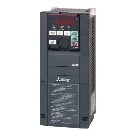
INVERTER
FR-A800
INSTALLATION GUIDELINE
FR-A820-00046(0.4K) to 04750(90K)
FR-A840-00023(0.4K) to 06830(280K)
FR-A842-07700(315K) to 12120(500K)
FR-A846-00023(0.4K) to 00470(18.5K)
Thank you for choosing this Mitsubishi Inverter.
This Installation guideline and the enclosed CD-ROM give handling information and precautions for use
of this product.
Do not use this product until you have a full knowledge of the equipment, the safety information and the
instructions.
Please forward this Installation guideline and the CD ROM to the end user.
Installation And Instructions..................................................................... 1
1
Outline Drawing ................................................................................................. 3
2
Wiring ...................................................................................................................... 5
3
4
Failsafe Of The System Which Uses The Inverter............................... 28
5
Precautions For Use Of The Inverter ..................................................... 29
6
Drive The Motor ................................................................................................ 31
7
Troubleshooting ............................................................................................. 50
Specifications ................................................................................................... 53
8
A
APPENDIX .............................................................................................................. 56
Art. No.: 274662
19 08 2014
Version check
Version D
CONTENTS
800
Advertisement
Table of Contents

Related Manuals for Mitsubishi Electric FR-A800


Summary of Contents for Mitsubishi Electric FR-A800
- Page 1 INVERTER FR-A800 INSTALLATION GUIDELINE FR-A820-00046(0.4K) to 04750(90K) FR-A840-00023(0.4K) to 06830(280K) FR-A842-07700(315K) to 12120(500K) FR-A846-00023(0.4K) to 00470(18.5K) Thank you for choosing this Mitsubishi Inverter. This Installation guideline and the enclosed CD-ROM give handling information and precautions for use of this product.
- Page 2 Print Date Art. no. Revision 11/2013 274662-A First edition 04/2014 274662-B Addition: FR-A840-03250(110K) to 06830(280K) Changes: Parameter list, Setting values, Protective functions 06/2014 274662-C Changes: Inverter type: rating and capacity plate Parameter list, Protective functions 08/2014 274662-D Additions: FR-A842-07700(315K) to 12120 (500K) (Separated converter type) FR-A846-00023(0.4K) to 00470(18.5K) (IP55 compatible model) For Maximum Safety Mitsubishi transistorized inverters are not designed or manufactured to be used in equipment or systems in situations...
- Page 3 A person who took a proper engineering training. Please note if you can take a proper engineering training at your local Mitsubishi Electric office. Such training may be available at your local Mitsubishi Electric office. Contact your local sales office for schedules and locations.
- Page 4 Injury Prevention CAUTION Apply only the voltage specified in the instruction manual to each terminal. Otherwise, burst, damage, etc. may occur. Ensure that the cables are connected to the correct terminals. Otherwise, burst, damage, etc. may occur. Always make sure that polarity is correct to prevent damage, etc. Otherwise, burst, damage, etc. may occur. While power is on or for some time after power-off, do not touch the inverter as it is hot and you may get burnt.
- Page 5 Operation WARNING When you have chosen the retry function, stay away from the equipment as it will restart suddenly after an alarm stop. Since pressing the key may not stop output depending on the function setting status, provide a circuit and switch separately to make an emergency stop (power off, mechanical brake operation for emergency stop, etc).
- Page 6 Disposing of the inverter CAUTION Treat as industrial waste. General instructions Many of the diagrams and drawings in instruction manuals show the inverter without a cover, or partially open. Never run the inverter in this status. Always replace the cover and follow instruction manuals when operating the inverter. For more details on the PM motor, refer to the Instruction Manual of the PM motor.
-
Page 7: Installation And Instructions
1 INSTALLATION AND INSTRUCTIONS 1.1 Inverter Type Symbol EMC Filter (IP55 FR - A8 0 00023 compatible models only) Built-in C2 filter Built-in C3 filter Circuit board Plated Symbol Voltage class Symbol Structure, functionality Symbol Description Symbol Type Symbol coating (3C2) conductor 00023 to SLD rated inverter... -
Page 8: Installation Of The Inverter
INSTALLATION AND INSTRUCTIONS 1.2 Installation of the inverter Install the inverter on a strong surface securely with bolts. Fix six positions for the FR-A840- 04320(160K) or higher and for the FR-A842 models (separated converter type). Leave enough clearances and take cooling measures. Avoid places where the inverter is subjected to direct sunlight, high temperature and high humidity. -
Page 9: Outline Drawing
2 OUTLINE DRAWING FR-A820-00046(0.4K) to 04750(90K) FR-A840-04320(160K) to 06830(280K) FR-A820-00046(0.4K) to 04750(90K) FR-A840-04320(160K) to 06830(280K) FR-A840-00023(0.4K) to 03610(132K) FR-A840-00023(0.4K) to 03610(132K) 3-φC 2-φC (Unit: mm) Inverter Type FR-A820-00046(0.4K) FR-A820-00077(0.75K) FR-A820-00105(1.5K) FR-A820-00167(2.2K) FR-A820-00250(3.7K) FR-A820-00340(5.5K) FR-A820-00490(7.5K) FR-A820-00630(11K) FR-A820-00770(15K) FR-A820-00930(18.5K) FR-A820-01250(22K) FR-A820-01540(30K) FR-A820-01870(37K) FR-A820-02330(45K) FR-A820-03160(55K) FR-A820-03800(75K) - Page 10 OUTLINE DRAWING FR-A842-07700(315K) to 12120(500K) FR-A846-00023(0.4K) to 00470(18.5K) 3-ØC 2-ØC (Unit: mm) Inverter Type FR-A842-07700(315K) 1330 1300 FR-A842-08660(355K) FR-A842-09620(400K) FR-A842-10940(450K) 1580 1550 FR-A842-12120(500K) FR-A846-00023(0.4K) to 00170(5.5K) FR-A846-00250(7.5K) to 632.5 00470(18.5K) For dimensions of the converter unit (FR-CC2) refer to the FR-CC2 Instruction Manual.
-
Page 11: Wiring
3 WIRING 3.1 Terminal connection diagrams 3.1.1 FR-A820/A840 FM type FR-A820-00770(15K)–01250(22K) Brake resistor FR-A840-00470(18.5K)–01800(55K) DC reactor (FR-ABR) *7*8 Brake resistor (FR-HEL) DC reactor (FR-ABR) (FR-HEL) Sink logic Brake unit (option) Brake unit Main circuit terminal (option) Control circuit terminal Earth Jumper Jumper... -
Page 12: Specifications
10 V), set the voltage/current input switch OFF. To input a current (4 to 20 mA), set the voltage/current input switch ON. Terminals 10 and 2 are also used as a PTC input terminal. (Pr. 561) (Refer to the FR-A800 Instruction Manual.) It is recommended to use 2W, 1kΩ... - Page 13 WIRING CA type FR-A820-00770(15K)–01250(22K) Brake resistor FR-A840-00470(18.5K)–01800(55K) DC reactor (FR-ABR) *7*8 Brake resistor (FR-HEL) DC reactor (FR-ABR) (FR-HEL) Source logic Brake unit (option) Brake unit Main circuit terminal (option) Control circuit terminal Earth Jumper Jumper Earth MCCB R/L1 Inrush current Motor 3-phase limit circuit...
-
Page 14: Fr-A820-00046(0.4K)
10 V), set the voltage/current input switch OFF. To input a current (4 to 20 mA), set the voltage/current input switch ON. Terminals 10 and 2 are also used as a PTC input terminal. (Pr. 561) (Refer to the FR-A800 Instruction Manual.) It is recommended to use 2W, 1kΩ... - Page 15 WIRING 3.1.2 FR-A842 FM type Sink logic Main circuit terminal Control circuit terminal Brake unit (option) Converter unit Motor R/L1 S/L2 T/L3 Jumper Earth R1/L11 S1/L21 Main circuit Earth Control circuit Relay output Control input signals Forward rotation start Reverse rotation start Relay output 1 (Alarm output) STP(STOP)
- Page 16 10 V), set the voltage/current input switch OFF. To input a current (4 to 20 mA), set the voltage/current input switch ON. Terminals 10 and 2 are also used as a PTC input terminal. (Pr. 561) (Refer to the FR-A800 Instruction Manual.) It is recommended to use 2W, 1kΩ...
- Page 17 WIRING CA type Source logic Main circuit terminal Control circuit terminal Brake unit (option) Converter unit Motor R/L1 S/L2 T/L3 Jumper R1/L11 Earth S1/L21 Main circuit Earth Control circuit Control input signals Relay output Forward rotation start Relay output 1 Reverse rotation start (Alarm output) STP(STOP)
- Page 18 10 V), set the voltage/current input switch OFF. To input a current (4 to 20 mA), set the voltage/current input switch ON. Terminals 10 and 2 are also used as a PTC input terminal. (Pr. 561) (Refer to the FR-A800 Instruction Manual.) It is recommended to use 2W, 1kΩ...
- Page 19 WIRING 3.1.3 FR-A846 FM type Sink logic Brake unit (option) Main circuit terminal Control circuit terminal Jumper Motor R/L1 Inrush current 3-phase limit circuit S/L2 AC power T/L3 supply EMC filter ON/OFF Earth connector Main circuit Earth Control circuit Relay output Control input signals Forward rotation start...
- Page 20 10 V), set the voltage/current input switch OFF. To input a current (4 to 20 mA), set the voltage/current input switch ON. Terminals 10 and 2 are also used as a PTC input terminal. (Pr. 561) (Refer to the FR-A800 Instruction Manual.) It is recommended to use 2W, 1kΩ...
- Page 21 WIRING CA type Source logic Brake unit (option) Main circuit terminal Control circuit terminal Jumper Motor R/L1 Inrush current 3-phase limit circuit S/L2 AC power T/L3 supply EMC filter ON/OFF Earth connector Main circuit Earth Control circuit Control input signals Relay output Forward rotation start Reverse rotation start...
- Page 22 10 V), set the voltage/current input switch OFF. To input a current (4 to 20 mA), set the voltage/current input switch ON. Terminals 10 and 2 are also used as a PTC input terminal. (Pr. 561) (Refer to the FR-A800 Instruction Manual.) It is recommended to use 2W, 1kΩ...
-
Page 23: Fr-A820-00770(15K)
WIRING 3.2 Main circuit terminal 3.2.1 Terminal layout and wiring FR-A820-00046(0.4K), 00077(0.75K) FR-A820-00105(1.5K) to 00250(3.7K) FR-A820-00340(5.5K), 00490(7.5K) FR-A840-00023(0.4K) to 00126(3.7K) FR-A840-00170(5.5K), 00250(7.5K) Jumper P/+ PR Jumper Jumper Jumper R1/L11 S1/L21 R/L1 S/L2 T/L3 Jumper R/L1 S/L2 T/L3 Jumper R/L1 S/L2 T/L3 R1/L11 S1/L21 R1/L11 S1/L21 Charge lamp... - Page 24 WIRING The following diagram shows the positions of R1/L11, S1/L21, and the charge lamp. Charge lamp Jumper R1/L11 S1/L21 The terminals P3 and PR of the FR-A820-01540(30K) are not equipped with screws. Do not connect anything to these. For terminal layout and wiring of the converter unit (FR-CC2) refer to the FR-CC2 Instruction Manual. CAUTION The power supply cables must be connected to R/L1, S/L2, T/L3.
-
Page 25: Fr-A820-01250(22K)
WIRING 3.3 Wiring fundamentals 3.3.1 Cable size Select the recommended cable size to ensure that a voltage drop will be 2% max. If the wiring distance is long between the inverter and motor, a main circuit cable voltage drop will cause the motor torque to decrease especially at the output of a low frequency. - Page 26 WIRING 400V class, FR-A840/A846 (when input power supply is 440V based on the rated current for 150% overload for 1 minute) Crimping Terminal Tightening Torque Applicable Inverter Type Terminal Screw Size * [Nm] R/L1, S/L2, T/L3 U, V, W FR-A840-00023(0.4K) to 00126(3.7K) FR-A840-00170(5.5K) FR-A840-00250(7.5K)
- Page 27 WIRING For the FR-A840-01800(55K) or lower and the FR-A846 (IP55 compatible) models, the recommended cable size is that of the HIV cable (600V class 2 vinyl-insulated cable) with continuous maximum permissible temperature of 75°C. Assumes that the surrounding air temperature is 50°C or less and the wiring distance is 20m or less. For the FR-A840-02160(75K) or higher, the recommended cable size is that of the LMFC cable (heat resistant flexible cross-linked polyethylene insulated cable) with continuous maximum permissible temperature of 90°C.
- Page 28 Refer to the FR-A800 Instruction Manual to drive a 400V class motor by an inverter. The carrier frequency is limited during PM sensorless vector control. (Refer to the FR-A800 Instruction Manual.) 3.3.3 Cable size of the control circuit power supply (terminal R1/L11, S1/L21) Terminal screw size: M4 Cable size: 0.75mm...
-
Page 29: Control Circuit Terminals
WIRING 3.4 Control circuit terminals 3.4.1 Terminal layout ∗1 1 F/C +24 SD So SOC S1 S2 PC Recommended cable gauge: 0.3 to 0.75mm² 5 10E 10 SE SE SU IPF OL FU PC RL RM RH RT AU STP MRS RES SD SD STF STR JOG The terminal functions as the terminal FM for the FM type, and as the terminal CA for the CA type. - Page 30 WIRING (3) Insert the wires into a socket. When using a single wire or stranded wires without a blade terminal, push the open/close button all the way down with a flathead screwdriver, and insert the wire. Open/close button Flathead screwdriver Wire removal Pull the wire while pushing the open/close button all the way down firmly with a flathead screwdriver.
- Page 31 WIRING 3.4.4 Control logic (sink/source) change Change the control logic of input signals as necessary. To change the control logic, change the jumper connector position on the control circuit board. Connect the jumper con- nector to the connector pin of the desired control logic. The control logic of input signals is initially set to the sink logic (SINK) for the FM type.
-
Page 32: Function Description
To prevent automatic restart after a fault occurrence, connect the reset button of a safety relay module or a safety pro- grammable controller across the terminals SO and SOC. The reset button acts as the feedback input for the safety relay module or the safety programmable controller. FR-A800 R/L1 S/L2 T/L3 Logic... - Page 33 WIRING 3.5.3 Safety stop function operation Input signal Output signal Internal safety Input power Inverter operation enable signal circuit failure S1-SIC S2-SIC — — — Output shutoff (Safe state) No failure Drive enabled Short Short Failure Output shutoff (Safe state) Output shutoff (Safe state) No failure Open...
- Page 34 4 FAILSAFE OF THE SYSTEM WHICH USES THE INVERTER When a fault is detected by the protective function, the protective function activates and output a fault signal (ALM). How- ever, a fault output signal may not be output at an inverter fault occurrence when the detection circuit or output circuit fails, etc.
-
Page 35: Precautions For Use Of The Inverter
5 PRECAUTIONS FOR USE OF THE INVERTER The FR-A800 series is a highly reliable product, but incorrect peripheral circuit making or operation/handling method may shorten the product life or damage the product. Before starting operation, always recheck the following items: Use crimping terminals with insulation sleeve to wire the power supply and motor. - Page 36 PRECAUTIONS FOR USE OF THE INVERTER Vector control is available with an encoder-equipped motor. And such an encoder must be directly connected to a motor shaft without any backlash. (Real sensorless vector control, PM sensorless control do not require an encoder.) Inverter input side magnetic contactor (MC) On the inverter input side, connect an MC for the following purposes.
- Page 37 Holding this key for 2 seconds locks the operation. The key lock is invalid when Pr. 161 ="0 (initial setting)". (Refer to the FR-A800 Instruction Manual.) Enters each setting. When the initial setting is set.
- Page 38 DRIVE THE MOTOR 6.1.2 Basic operation (factory setting) Operation mode switchover/frequency setting External operation mode (At power-ON) PU operation mode PU JOG operation mode Flicker Example Frequency setting has been written Value change and completed! Output current monitor Output voltage monitor Parameter setting mode (At power-ON) Display the present setting...
-
Page 39: Fr-A820-03800(75K)
DRIVE THE MOTOR 6.2 Parameter list For simple variable-speed operation of the inverter, the initial values of the parameters may be used as they are. Set the necessary parameters to meet the load and operational specifications. Parameter setting, change and check can be per- formed from the operation panel (FR-DU08, resp. - Page 40 DRIVE THE MOTOR Initial Initial Parameter Name Setting Range Parameter Name Setting Range Value Value 0 to 590Hz, Starting frequency Frequency jump 3B 9999 9999 0 to 10Hz, 9999 9999 for elevator mode Speed display 0, 1 to 9998 Retry selection 0 to 5 Up-to-frequency Stall prevention...
- Page 41 DRIVE THE MOTOR Initial Initial Parameter Name Setting Range Parameter Name Setting Range Value Value Speed control gain 48, 96, 192, PU communication 384, 576, 768, (Advanced magnetic 9999 0 to 200%, 9999 speed 1152 flux vector) PU communication 0 to 50Ω, stop bit length / 0, 1, 10, 11 9999...
- Page 42 DRIVE THE MOTOR Initial Initial Parameter Name Setting Range Parameter Name Setting Range Value Value Backlash Stall prevention acceleration 0.5s operation level for 150% 0 to 360s 0 to 400% stopping time restart Backlash Output current deceleration detection signal 0.1s 0 to 590Hz 0 to 10s, 9999 stopping frequency...
- Page 43 DRIVE THE MOTOR Initial Initial Parameter Name Setting Range Parameter Name Setting Range Value Value Power-failure 0 to 3600s, 265 * 9999 Multi-speed setting 0 to 590Hz, deceleration time 2 9999 9999 (speeds 8 to 15) 9999 Power failure deceleration time 266 * 0 to 590Hz 60/50Hz...
- Page 44 DRIVE THE MOTOR Initial Initial Parameter Name Setting Range Parameter Name Setting Range Value Value 0, 1, 10, 11, 20, Communication error — Pulse train I/O 21, 100 count (FM type) selection Stop position 0,1 (CA type) 9999 0, 1, 9999 command selection Automatic Orientation speed...
- Page 45 DRIVE THE MOTOR Initial Initial Parameter Name Setting Range Parameter Name Setting Range Value Value 0, 1, 3 to 6, 13 to Orientation selection 0 to 2 16, 20, 23, 24, 30, 33, 34, 40, Orientation speed 0 to 1000 43, 44, 50, 53, gain (P term) Second applied...
- Page 46 DRIVE THE MOTOR Initial Initial Parameter Name Setting Range Parameter Name Setting Range Value Value Second target Twelfth target position upper 4 position upper 4 digits digits Third target position Thirteenth target lower 4 digits position lower 4 digits Third target position upper 4 digits Thirteenth target position upper 4...
- Page 47 DRIVE THE MOTOR Initial Initial Parameter Name Setting Range Parameter Name Setting Range Value Value USB communication Amplitude 0 to 999.8s, 9999 check time interval 9999 compensation 0 to 50% amount during Protocol selection 0, 1 acceleration NET mode operation Amplitude command source 9999...
- Page 48 DRIVE THE MOTOR Initial Initial Parameter Name Setting Range Parameter Name Setting Range Value Value Second brake Second free thermal 0 to 590Hz, 9999 operation time at 0.3s reduction frequency 2 9999 0 to 5s stop Second free thermal 100% 1 to 100% Second deceleration reduction ratio 2...
- Page 49 DRIVE THE MOTOR Initial Initial Parameter Name Setting Range Parameter Name Setting Range Value Value 0, 10, 11, 20, 21, Operation frequency 0 to 590Hz, 50, 51, 60, 61, during 9999 9999 70, 71, 80, 81, communication error 90, 91, 100, Second PID action Low speed range 101, 1000,...
- Page 50 DRIVE THE MOTOR Initial Initial Parameter Name Setting Range Parameter Name Setting Range Value Value Torque limit level Torque bias filter 9999 0 to 5s, 9999 9999 0 to 400%, 9999 during deceleration Torque bias 9999 Easy gain tuning 0 to 5s, 9999 operation time response level 1 to 15...
- Page 51 DRIVE THE MOTOR Initial Initial Parameter Name Setting Range Parameter Name Setting Range Value Value Speed feed forward Terminal 2 frequency 0 to 1s 0 to 300% filter setting bias (902) Speed feed forward 150% 0 to 400% Terminal 2 frequency torque limit setting gain 0 to 590Hz...
- Page 52 DRIVE THE MOTOR Initial Initial Parameter Name Setting Range Parameter Name Setting Range Value Value Fault initiation 9999 0 to 255, 9999 Current output bias (930) 0 to 100% 0, 3003, 3103, PM parameter current 8009, 8109, *9,*11 initialization Simple Simple Simple 9009, 9109...
- Page 53 DRIVE THE MOTOR Initial Initial Parameter Name Setting Range Parameter Name Setting Range Value Value Analog source Swinging 1027 1073 selection (1ch) suppression control 0, 1 operation selection Analog source 1028 selection (2ch) Swinging 0.05 to 3Hz, 1074 suppression Analog source 9999 1 to 3, 5 to 14, 1029...
- Page 54 DRIVE THE MOTOR Initial Initial Parameter Name Setting Range Parameter Name Setting Range Value Value Second PID set Fourth positioning 1234 0.01 to 360s 1140 point/deviation input acceleration time 1 to 5 selection Fourth positioning 1235 0.01 to 360s Second PID deceleration time 1141 measured value...
- Page 55 DRIVE THE MOTOR Initial Initial Parameter Name Setting Range Parameter Name Setting Range Value Value Tenth positioning Fifteenth positioning 0, 1, 10, 11, 100, 1258 1281 0.01 to 360s acceleration time subfunction 101, 110, 111 Tenth positioning Home position return 1259 1282 0.01 to 360s...
-
Page 56: Troubleshooting
When the protective function is activated, the inverter output is shut off and a fault signal is output. NOTES For the details of fault displays and other malfunctions, also refer to the FR-A800 Instruction Manual. Past eight faults can be displayed using the setting dial. (Refer to page 32.) -
Page 57: Reset Method Of Protective Function
TROUBLESHOOTING 7.1 Reset method of protective function The inverter can be reset by performing any of the following operations. Note that the internal thermal integrated value of the electronic thermal relay function and the number of retries are cleared (erased) by resetting the inverter. Inverter recovers about 1s after reset is cancelled. - Page 58 TROUBLESHOOTING Operation Panel Data Operation Panel Data Name Name Indication code Indication code Inverter overload trip (electronic Abnormal output current E.THT E.CDO (H30) (HC4) thermal relay function) detection Motor overload trip (electronic Inrush current limit circuit E.THM E.IOH (H31) (HC5) thermal relay function) fault Communication fault...
- Page 59 8 SPECIFICATIONS 8.1 Rating 8.1.1 FR-A820 (200V class) 00046 00077 00105 00167 00250 00340 00490 00630 00770 00930 01250 01540 01870 02330 03160 03800 04750 Model FR-A820- (0.4K) (0.75K) (1.5K) (2.2K) (3.7K) (5.5K) (7.5K) (11K) (15K) (18.5K) (22K) (30K) (37K) (45K) (55K) (75K)
- Page 60 SPECIFICATIONS 8.1.2 FR-A840 (400V class) 00023 00038 00052 00083 00126 00170 00250 00310 00380 00470 00620 00770 00930 01160 01800 02160 02600 03250 03610 04320 04810 05470 06100 06830 Model FR-A840- (0.4K) (0.75K) (1.5K) (2.2K) (3.7K) (5.5K) (7.5K) (11K) (15K) (18.5K) (22K) (30K)
- Page 61 FR-DU08: IP40 (except for the PU connector section) For the power voltage exceeding 480V, set Pr. 977 "Input voltage mode selection". (For details, refer to the FR-A800 Instruction Manual.) For ratings of the converter unit (FR-CC2) refer to the FR-CC2 Instruction Manual.
- Page 62 The inverter (resp. the converter unit for separated converter types) is equipped with a built-in EMC filter. Set the EMC filter valid. (For details, refer to the FR-A800 and FR-CC2 Instruction Manuals.) Connect the inverter (and the converter unit) to an earthed power supply.
- Page 63 APPENDIX A.1.2 Low Voltage Directive We have self-confirmed our inverters as products compliant to the Low Voltage Directive (conforming standard EN 61800-5-1) and place the CE mark on the inverters. Outline of instructions Do not use an earth leakage current breaker as an electric shock protector without connecting the equipment to the earth.
- Page 64 APPENDIX Wiring protection For installation Class T, Class J, or Class CC fuse or UL 489 Molded Case Circuit Breaker (MCCB) according to the local directives must be provided. 00046 00077 00105 00167 00250 00340 00490 00630 00770 00930 01250 01540 FR-A820- (0.4K)
- Page 65 APPENDIX A.2 Instructions for UL and cUL (Conforming standard UL 508C, CSA C22.2 No.14) A.2.1 General precautions WARNING The bus capacitor discharge time is 10 minutes. Before starting wiring or inspection, switch power off, wait for more than 10 minutes, and check for residual voltage between terminal P/+ and N/- with a meter etc., to avoid a hazard of electrical shock.
- Page 66 APPENDIX A.2.5 Motor overload protection When using the electronic thermal relay function as motor overload protection, set the rated motor current to Pr. 9 "Elec- tronic thermal O/L relay". Electronic thermal relay function operation characteristic This function detects the overload (overheat) of the Pr.
- Page 68 Phone: +371 (0)6 / 784 2280 Fax: +371 (0)6 / 784 2281 Mitsubishi Electric Europe B.V. / FA - European Business Group / Gothaer Straße 8 / D-40880 Ratingen / Germany / Tel.: +49(0)2102-4860 / Fax: +49(0)2102-4861120 / info@mitsubishi-automation.com / https://eu3a.mitsubishielectric.com...