Table of Contents
Advertisement
Quick Links
Service
Manual
SECTION
1. MAIN UNIT
1.1 TECHNICAL SPECIFICATIONS ......................................................................................................... 1-1
1.2 REGIONAL CODES ............................................................................................................................ 1-2
1.3 INFORMATIONS ................................................................................................................................. 1-3
1.4 SERVICING HINT ............................................................................................................................... 1-4
1.5 DISASSEMBLY ................................................................................................................................... 1-5
1.6 REPLACEMENT OF PRINCIPAL COMPONENTS ............................................................................. 1-6
1.7 SERVICE MODE ................................................................................................................................. 1-8
1.8 ELECTRICAL ADJUSTMENT ........................................................................................................... 1-10
1.9 WAVEFORM ..................................................................................................................................... 1-12
1.10 WIRING DIAGRAM ........................................................................................................................... 1-13
1.11 BLOCK DIAGRAM ............................................................................................................................. 1-15
1.12 SCHEMATIC DIAGRAM .................................................................................................................... 1-17
1.13 PARTS LOCATION ........................................................................................................................... 1-27
1.14 EXPLODED VIEW AND PARTS LIST ............................................................................................... 1-30
1.15 ELECTRICAL PARTS LIST ............................................................................................................... 1-33
2. TKM1000MZ ( DVD MODULE for MARANTZ )
2.1 SCHEMATIC DIAGRAM AND PARTS LOCATION ............................................................................. 2-1
2.2 MICROPROCESSOR AND IC DATA ................................................................................................ 2-15
2.3 EXPLODED VIEW AND PARTS LIST ............................................................................................... 2-28
2.4 ELECTRICAL PARTS LIST ............................................................................................................... 2-30
Please use this service manual with referring to the user guide ( D.F.U. ) without fail.
Printed in Japan
A-B
SURROUND
TITLE
V I D E O
STANDBY
DIMMER
SHUFFLE
POWER
TABLE OF CONTENTS
DV-18
DV18 /
F1N, /K1G, /S1G, /U1G, /U1B
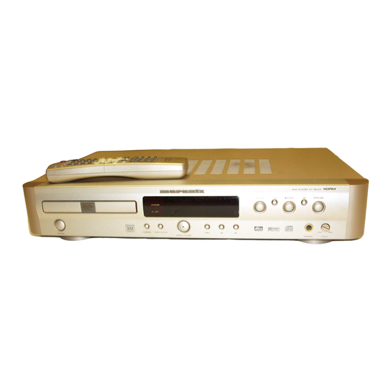
DVD PLAYER DV-18
PLAY
STOP
REPEAT
SHUFFLE
SVCD
SCAN
CHAPTER
TITLE
TRACK
CHAPTER
TRACK
PBC
FTS
TOTAL
TRACK
TIME
DIGITAL OUT
SCAN
PHONES
OPEN/CLOSE
DVD Player
PAUSE
MIN
MAX
LEVEL
PAGE
R
370K855010 MIT
First Issue 2000.09
Advertisement
Table of Contents

Subscribe to Our Youtube Channel
Related Manuals for Marantz dv18


Summary of Contents for Marantz dv18
- Page 1 1.13 PARTS LOCATION ........................... 1-27 1.14 EXPLODED VIEW AND PARTS LIST ....................1-30 1.15 ELECTRICAL PARTS LIST ....................... 1-33 2. TKM1000MZ ( DVD MODULE for MARANTZ ) 2.1 SCHEMATIC DIAGRAM AND PARTS LOCATION ................2-1 2.2 MICROPROCESSOR AND IC DATA ....................2-15 2.3 EXPLODED VIEW AND PARTS LIST ....................
- Page 2 MARANTZ Parts for your equipment are generally available to our National Marantz Subsidiary or Agent. ORDERING PARTS : Parts can be ordered either by mail or by Fax.. In both cases, the correct part number has to be specified.
-
Page 3: Technical Specifications
1. TECHNICAL SPECIFICATIONS Discs played DVD video disc ..........12 cm single sided, single layer 12 cm single sided, double layer 12 cm double sided, single layer 12 cm double sided, double layer (one layer per side) 8 cm single sided, single layer 8 cm single sided, double layer 8 cm double sided, single layer 8 cm double sided, double layer (one layer per side) -
Page 4: Regional Codes
2. REGIONAL CODES What are "regional codes"? Motion picture studios want to control the home release of movies in different countries because theater releases arenít simultaneous (a movie may come out on DVD in the US when itís just hitting screens in Europe). Therefore they have required that the DVD standard include codes which can be used to lock out the playback of certain discs in certain geo- graphical regions. -
Page 5: Informations
3. INFORMATIONS REGION CODE Chapter: A title may also be separated into chapters. VERSION REGION CODE COUNTRY For example, a movie (title) may be separated into 3 scenes /FXX JAPAN (chapters). /KXX CHINA /SXX SINGAPORE/HONGKONG Title 1 Title 2 /UXX USA/CANADA Chapter Chapter... -
Page 6: Servicing Hint
4. SERVICING HINT SERVICE HINTS SERVICE TOOLS Audio signals disc 4822 397 30184 Disc without errors (SBC444)+ Disc with DO errors, black spots and fingerprints (SBC444A) 4822 397 30245 Disc (65 min 1kHz) without no pause 4822 397 30155 Max. diameter disc (58.0 mm) 4822 397 60141 Torx screwdrivers Set (straight) -
Page 7: Disassembly
5. DISAS SEMBLY 5. DISASSEMBLY 5. DISASSEMBLY 5. DISASSEMBLY 5. DISASSEMBLY 5. DISASSEMBLY 1. Remove 6 screws and remove the top cover. (see Fig.5- 1. ネジを 6 本外し、トップカバーを 外します。 (Fig.5-1) 2. ケーブルホルダーを 緩め、DVD メイン基板 <-> PP01 間の 2. Lose the cable holder. Remove the housing of the wire ケーブルを... -
Page 8: Replacement Of Principal Components
6. REPLACEMENT OF PRINCIPAL COMPONENTS 6-1-2. Removal of the TRAVERSE MECHA. 6-1. Removal of the TRAVERSE MECHA. 1) Remove the four b screws on the MAIN PCB and then 6-1-1. Removal of the MECHANISM BLOCK disconnect the P800 connector on the MAIN PCB. 1) Turn the unit s power on and press the "EJECT"... - Page 9 3) Carefully disconnect the two connectors (P500, P600) and 6-3. Replacement of the PICK UP BLOCK the two flat cables (P200, P300) on the MECHANISM PCB. Replacement of the PICK UP BLOCK itself is not recommended because its azimuth adjustment is very critical and requires a special jig.
-
Page 10: Service Mode
7. SERVICE MODE FLD, LED TEST FLD, LED FLD, LED FLD, LED FLD, LED FLD, LED の確認のしかた の確認のしかた の確認のしかた の確認のしかた の確認のしかた 1. Press the mains switch (POWER BUTTON) while 1. PAUSE PAUSE PAUSE PAUSE PAUSE ボタンと STOP STOP STOP STOP STOP ボタンを同じに押しながら、電源ス... - Page 11 Type version confirmation 製品仕向の確認のしかた 製品仕向の確認のしかた 製品仕向の確認のしかた 製品仕向の確認のしかた 製品仕向の確認のしかた NO DISC NO DISC 1. Power ON the DVD player. The FL display must be 1. Disc が入っていない状態で、ディスプレイに[NO DISC NO DISC NO DISC]と shown <NO DISC>. 表示されている事を確認します。 2. Pressing the button and button simultaneously.
-
Page 12: Electrical Adjustment
8. ELECTRICAL ADJUSTMENT VR120 P800 P804 P803 TP120 TP105 TP107 VR121 TP300 VR110 JITTER ADJ JITTER ADJ SCREW A SCREW B VR202 Fig. 8-1 8-1. DVD JITTER ADJUSTMENT 2. Set the oscilloscope to the DC input mode and connect it to 1. - Page 13 8-4 AS Adjustment 8-4 AS 8-4 AS 調整 調整 8-4 AS 8-4 AS 8-4 AS 調整 調整 調整 CAUTION : 注意 注意 注意: : : : : 注意 注意 Do not see the laser pick-up! Cover the laser pick-up unit Laser Laser Laser...
-
Page 14: Waveform
9. WAVEFORM Power requirements (Refer the circuit diagram page 1-25 and 1-26) 100V AC 120V AV 220V AC 5µsec 5µsec 5µsec 5µsec 5µsec 5µsec 5µsec 5µsec 5µsec 0.1V 5µsec 0.1V 5µsec 0.1V 5µsec 1-12... - Page 15 1.10 WARNINGS 1-13 1-14...
-
Page 16: Block Diagram
1.11 BLOCK DIAGRAM 1-15 1-16... -
Page 17: Schematic Diagram
1.12 SCHEMATIC DIAGRAM AND PARTS LOCATION 1-17 1-18... - Page 18 1-19 1-20...
- Page 19 REPEAT SHUFFLE SCAN CHAPTER TITLE TRACK TITLE CHAPTER TRACK TOTAL TRACK TIME 1-21 1-22...
- Page 20 1-23 1-24...
-
Page 21: Parts Location
1.13 PARTS LOCATION PF01 QF11 QF01 QF05 - QF07 QF08 QF04 QF10 QF09 QF2 QF03 PP01 QP05 QP07 QP18 QP19 QP01 QP03 QP04 QP12 QP14 QP13 QP09 QP08 QP06 QP20 - QP22 QP02 QP25 QP24 QP13 QP11 QP10 1-25 1-26... - Page 22 PV01 QS04 QS02 QS01 QS03 QS05 QS07 QS06 QH02 - QH12 QH03 - QH11 QV10 QV05 QV08 QV15 QV12 QS08 QS09 (Even number) (Odd number) QV03 QV02 QV07 QV06 QV09 QV10 QV16 QV13 QV17 QV18 QS14 QS12 QS15 - QS18 QS11 QS13 QV04...
- Page 23 PK01 QK03 QK05 QK01 QK04 QK06 PS01 1-29...
- Page 24 9965 000 00580 KNOB PHONE GLD 284T154240 035B BLACK 4822 411 20336 KNOB PHONE BLK 284T154310 040B GOLD 9965 000 01554 BADGE 313J251110 NEW MARANTZ BADGE GLD 040B BLACK 9965 000 01553 BADGE 313J251010 NEW MARANTZ BADGE BLK 045B GOLD BUTTON POWER GLD 370K270110...
- Page 25 5 1 2 9 3 x 8 ( M) 5 1 2 6 TO P COV E R S CRE WS 3 x 8 ( U, M) BL A CK : ( U) GOL D ( M) PA RT S NAME MA RK MA T E RI A L / F I N I S H SYM BO L...
- Page 26 1.15 ELECTRICAL PARTS LIST POS. VERS. PART NO. POS. VERS. PART NO. PART NO. PART NO. DESCRIPTION DESCRIPTION NOTE ON SAFETY FOR FUSIBLE RESISTOR : ASSIGNMENT OF COMMON PARTS CODES. COLOR (FOR PCS) COLOR (FOR PCS) (MJI) (MJI) RESISTORS The suppliers and their type numbers of fusible resistors : 1) GD05 ×...
- Page 27 VERS. PART NO. VERS. POS. POS. PART NO. PART NO. PART NO. DESCRIPTION DESCRIPTION COLOR COLOR (FOR PCS) (FOR PCS) (MJI) (MJI) PK01- SEMICONDUCTORS RP09 4822 116 82107 METAL 68kΩ ±5% 3W NK05683030 QK01 4822 209 31378 IC NJM4556 HC10045090 RP10 /F1, /U1 9965 000 00402 METAL 0.47Ω...
- Page 28 VERS. PART NO. VERS. POS. POS. PART NO. PART NO. PART NO. DESCRIPTION DESCRIPTION COLOR COLOR (FOR PCS) (FOR PCS) (MJI) (MJI) DP13 CHIP DIODE ZENER HZ30014050 FC01 4822 526 10696 FERRITE CORE FC50150010 02CZ3.3X 3.3V TFC-23-11-14 WITH TFP2014-V DP14 CHIP DIODE SFPL-52 HZ20002080 FP01 /F1, /U1...
- Page 29 VERS. PART NO. VERS. POS. POS. PART NO. PART NO. PART NO. DESCRIPTION DESCRIPTION COLOR COLOR (FOR PCS) (FOR PCS) (MJI) (MJI) CV19 4822 126 11661 CER. CHIP 5pF DD90050300 RH07 4822 116 90503 CHIP 150Ω ±5% 1/10W NI05151110 CV20 4822 122 33777 CER.
- Page 30 VERS. PART NO. VERS. POS. POS. PART NO. PART NO. PART NO. DESCRIPTION DESCRIPTION COLOR COLOR (FOR PCS) (FOR PCS) (MJI) (MJI) RV08 4822 051 30222 CHIP 2.2kΩ ±5% 1/16W NN05222610 DS01 4822 130 83229 CHIP DIODE 02CZ3.9X HZ30024050 RV09 4822 051 30471 CHIP 470Ω...
- Page 31 VERS. POS. PART NO. PART NO. DESCRIPTION COLOR (FOR PCS) (MJI) QV13 CHIP TRS. 2SC4081 Q OR R HX300012A0 2SC4116 Y OR GR QV14 4822 209 14876 IC MC14577C SOP HC10065170 QV15 CHIP TRS. 2SC4081 Q OR R HX300012A0 2SC4116 Y OR GR QV16 CHIP TRS.
- Page 32 <C3M1>.aaaaaaaaaaaaa TABLE OF CONTENTS SECTION PAGE 2. TKM1000MZ ( DVD MODULE for MARANTZ ) 2.1 SCHEMATIC DIAGRAM AND PARTS LOCATION ................2-1 2.2 MICROPROCESSOR AND IC DATA ....................2-15 2.3 EXPLODED VIEW AND PARTS LIST ....................2-28 2.4 ELECTRICAL PARTS LIST ....................... 2-30 Please use this service manual with referring to the user guide ( D.F.U.
- Page 33 MARANTZ Parts for your equipment are generally available to our National Marantz Subsidiary or Agent. ORDERING PARTS : Parts can be ordered either by mail or by Fax.. In both cases, the correct part number has to be specified.
-
Page 34: Schematic Diagram And Parts Location
2.1 SCHEMATIC DIAGRAM AND PARTS LOCATION Not for DV4000... - Page 36 Not for DV4000...
- Page 37 MAIN TOP VIEW TR113 TR115 TR802 TR801 TR100 ~TR106 IC122 IC121 IC120 TR804 ~TR806 TR300 IC507 IC503 TR500 IC111 TR120 TR201 TR202 TR190 IC202 IC203 TR200 IC311 IC607 IC610 ~IC613 IC502 IC702 IC501...
- Page 38 IC911 MAIN BOTTOM VIEW IC701 IC851 IC606 IC850 IC801 IC901 IC802 IC991 IC971 TR114 IC600 IC700 IC703 IC602 IC605 IC800 IC803 TR112 IC110 IC951 TR111 IC500 IC550 IC614 IC852 TR490 TR491 IC490 TR600 IC603 IC300 IC201 TR117 TR167 IC100 TR170 ~TR712 IC931 TR110 TR125...
- Page 39 2-11 2-12...
- Page 40 MECHA TOP VIEW MECHA BOTTOM VIEW TR34 TR90 TR37 TR35 TR36 TR32 TR31 TR33 LOADING MT100 2-13 2-14...
-
Page 41: Microprocessor And Ic Data
2.2 MICROPROCESSOR AND IC DATA CYC11AP000 (DVD Pre AMP) ADV7172 (Video signal decoder) 2-15 2-16... - Page 42 CYC12MP000(DVD Read Channel) 2-17...
- Page 43 MB90574 (CPU/System control MI-COM) Pin No. Port Name FUNCTION System bus read strobe signal output. System bus lower 8 bit write strobe signal output. BOOT Ziva MI-COM transmission control output. CDLOW Disc judge output. LD.SW1 Laser control output 1. System bus ready input. LD.SW2 Laser control output 2.
- Page 44 Pin No. Port Name FUNCTION AVRTM ECC interruption request input (end of output stream of 2060 bytes data) . 68,69 DGND Ð Ground for digital section. SDA(I2C) Serial data in/out from/to EEP-ROM & video encoder. Serial clock output to the EEP-ROM & video encoder. STAT CD-DSP status input.
- Page 45 MN66261 (CD signal processing) 2-20...
- Page 46 MN66261 (CD signal processing) 2-21...
- Page 47 MN67700 (Servo processing IC) 2-22...
- Page 48 MN67700 (Servo processing IC) 2-23...
- Page 49 YMC13D000 (DVD Sync/ECC/Formatter) Pin No. Port Name FUNCTION 1,12,26,35,46, 52,63,73,81, 95,105,118, VSS1-18 Ð Ground pins. 131,142,156, 170,182,195 SEL0 Ð Test mode select pins. SEL1 4-6,8,10,10 11,14-22,28 29,116,117 119,125,126 TEST9-46 Ð Test mode output pins. (Leave them open) 132,171-174 194,197-206 AVRTM End of output stream of 2060 bytes data to CSS.
- Page 50 Pin No. Port Name FUNCTION 127-130 133-139 CPUADT0-15 CPU address/data bus. 143-147 XRESET Global reset input. 148-152 CPUADT16-20 CPU address bus. XALE Address latch enable input. Read strobe. XINTO ECC interrupt request. XWEH Write strobe signal. XWAIT CPU wait state control. XHSTCS Decipher chip select.
- Page 51 ZIVA-3 (Advanced DVD decoder with integrated Audio DSP) Pin No. Port Name FUNCTION 1,52,129 133,138,141 PIO0-10 Programmable I/O pins. 147,153,156 174,190 2-4,6,8-11 HDATA0-7 8 bit bi-directional host data bus. 5,12,17,27 36,40,47,55 61,65,69,75 81,87,91.95 VDD1-29 Ð +3.3 V power supply pins. 101,107,113 117,123,134 149,160,181...
- Page 52 Pin No. Port Name FUNCTION DA-LRCK PCM left/right clock. Identifies the channel for each audio sample. DA-BCK PCM bit clock output. DA-XCK Audio master frequency clock. DAI-DATA PCM input DATA (not used). DAI-LRCK PCM input LRCK (not used). DAI-BCK PCM input BCK (not used). CLKSEL Clock select pin.
-
Page 53: Exploded View And Parts List
2.3 EXPLODED VIEW AND PARTS LIST (TKM1000MZ) 2-28... - Page 54 (VERS. :VERSION, U:U.S.A., F:JAPAN, K:FAR EAST, ** :EUROPE) VERS. POS. PART NO. PART NO. DESCRIPTION COLOR (FOR PCS) (MJI) 9965 000 04593 PLATE CLAMP 294W051010 9965 000 04594 MAGNET 294W012010 9965 000 04595 DISC CLAMP 294W005010 ST PAN26X06STL CMT PT PAN20X05STL CMT C060 9965 000 04596 GEAR LOAD 2 294W058010 9965 000 04597 SLIDER UD...
-
Page 55: Electrical Parts List
2.4 ELECTRICAL PARTS LIST (TKM1000MZ) NOTE ON SAFETY FOR FUSIBLE RESIST OR : ASSIGNMENT OF COMMON P ARTS CODES. RESISTORS The suppliers and their type numbers of fusible resistors are as 1) GD05 x x x 140, Carbon film fixed resistor, 5% 1/4W follows ;... - Page 56 (VERS. :VERSION, U:U.S.A., F:JAPAN, K:FAR EAST, ** :EUROPE) POS. VERS. PART NO. POS. VERS. PART NO. PART NO. PART NO. DESCRIPTION DESCRIPTION COLOR (FOR PCS) COLOR (FOR PCS) (MJI) (MJI) MAIN CIRCUIT BOARD TR106 9965 000 04651 UMG4N BA21711000 DIODES TR110 4822 130 63618 FET 2SK880 HY208802B0...
Need help?
Do you have a question about the dv18 and is the answer not in the manual?
Questions and answers