Table of Contents
Advertisement
Please read and save these instructions. Read carefully before attempting to assemble, install, operate or maintain the product
described. Protect yourself and others by observing all safety information. Failure to comply with instructions could result in
personal injury and/or property damage! Retain instructions for future reference.
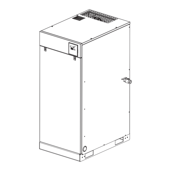
Description
Powerex Scroll Enclosure Air Compressors are designed to
supply continuous oil-free air by using the most advanced
scroll technology. These turn-key packages are extremely
quiet and offer electronic control that will reduce electrical
power consumption.
The Powerex Oilless Rotary Scroll Air Compressor has
advanced scroll compressor technology through the
development of a completely oilless unit. The Powerex Scroll
Compressor offers a dynamically balanced air end which
insures vibration-free operation. The rotary design permits a
continuous 100% duty cycle. No oil separation, oil fi ltration,
or inlet valves are required on the Powerex Scroll unit. The
compressor is virtually maintenance free.
The Powerex Oilless Rotary Scroll Air Compressor is based on
the theory of scroll compression. A scroll is a free standing,
intricate spiral bounded on one side by a solid, fl at plane or
base. A scroll set, the basic compression element of a scroll
compressor, is made up of two identical spirals which form
right and left hand parts. One of these scroll components
is indexed or phased 180° with respect to the other so the
scrolls can mesh. Crescent-shaped gas pockets are formed
and bounded by the spirals and the base plate of both
scrolls. As the moving scroll is orbited around the fi xed scroll,
the pockets formed by the meshed scrolls follow the spiral
toward the center and diminish in size. The moving scroll is
prevented from rotating during this process so the 180° phase
relationship of the scrolls is maintained. The compressor's
inlet is at the outer boundary of the scrolls. The entering
gas is trapped in two completely opposite gas pockets and
compressed as the pockets move toward the center. The
compressed gas is discharged through the outlet at the center
of the fi xed scroll so no valves are needed.
Powerex • 150 Production Drive • Harrison, OH 45030 • USA
1-888-769-7979
Scroll Enclosure Air Compressor
Specifi cations
Product
SED, SET, SEQ, SEH and SEO Series
Performance
See Page 2
Specifi cations
Lubrication
Grease-fi lled Bearings / Dry Scroll
Operating Voltages
3Ø 208-230/460 Volts, 60 Hz
Compression Cycle
Scroll
Motor Overload
IEC Motor Overload Relay
Protection
Pressure Settings
Cut-In: 94 psig
Working Pressure
Cut-In: 116 psig Cut-Out: 145 psig
Overpressure
Safety Valve Factory Set and Sealed
Protection
Outlet Air
See Page 2
Connections
Minimum
See Page 5, Chart 2
Recommended Tank
Sizes
Unit Isolation
Standard All Units
Drive
3V Belt
Control Panel
UL508A Listed for medical units
Cut-Out: 116 psig
(High Pressure Unit)
IN558804AV 6/12
Advertisement
Table of Contents

Related Manuals for Powerex SED1007


Summary of Contents for Powerex SED1007
- Page 1 The rotary design permits a continuous 100% duty cycle. No oil separation, oil fi ltration, or inlet valves are required on the Powerex Scroll unit. The compressor is virtually maintenance free. The Powerex Oilless Rotary Scroll Air Compressor is based on the theory of scroll compression.
-
Page 2: Safety Guidelines
Damage may result in bursting and cause injury or property damage. The compressor nameplate should be checked to see if the unit is the correct model and voltage as ordered. Figure 2 Performance Specifi cations Model SED1007 SED1007HP SET1507 SET1507HP SEQ2007 SEQ2007HP SEH3007... -
Page 3: Breathable Air Warning
IN-LINE SAFETY AND ALARM EQUIPMENT IS NOT compressor such as the air end, discharge pipe, SIMULTANEOUSLY USED, EXISTING WARRANTIES ARE aftercooler, motor, etc. VOIDED, AND POWEREX DISCLAIMS ANY LIABILITY WHATSOEVER FOR ANY LOSS, PERSONAL INJURY OR Keep fl ammable gases away from the compressor. Parts DAMAGE. -
Page 4: Installation Site
Scroll Enclosure Air Compressors General Safety Information Installation (Continued) INSTALLATION SITE 15. Always provide a clean air source for your compressor. The scroll compressor must be located in a clean, well lit Keep all piping direct and short when using an outside and well ventilated area. -
Page 5: Safety Valves
Scroll Enclosure Air Compressors Installation (Continued) SAFETY VALVES The fl ow capacity of a safety valve should be equal to or 2) Install the exhaust duct in order to minimize the greater than the capacity of the compressor. pressure lost of the ducting. Keep the distance between The pressure setting of the safety valve must not be the inlet duct and the compressor exhaust to be at least greater than the maximum working pressure of the air... -
Page 6: Start-Up And Operation
Scroll Enclosure Air Compressors Have a qualifi ed electrician switch the breaker OFF Operation and exchange two out of three phases of electric source. BEFORE START UP Check the discharge pressure. Also make sure the air Make sure all safety warnings, labels and instructions pressure rises to the designated pressure setting by have been read and understood before continuing. - Page 7 Scroll Enclosure Air Compressors Multi-Stage Control As this compressor uses plural air ends, it employs multi-stage control. It can start and stop each air end according to pressure and air consumption, automatically select the number of air ends in accordance with air consumption and achieve optimum and uniform operation at all times as well as energy-saving and labor-saving operation.
-
Page 8: Operating Panel
Scroll Enclosure Air Compressors The Early Caution maintenance alarm becomes effective Operating Panel by installing a Early Caution maintenance connector. By doing so, the maintenance alarm will be activated at DISPLAY MODE 7800 hours (2000 hours earlier than maintenance There are fi ve modes of display: Operation, Caution, Service, alarm 1). - Page 9 Scroll Enclosure Air Compressors Operating Panel (Continued) Items Display Explanation Displays compressor outlet pressure in psig Pressure (Display on the left means 68 psig.) Displays operating time in hours x10. Operating (Display on the left means 230 hours.) Time * Number of Hours that any pump is running x load factor (between 0 to 1 depending on how many pumps are running) Displays operating condition of of air ends No.
- Page 10 Scroll Enclosure Air Compressors Operating Panel (Continued) Items Display Explanation Emergency Shows causes for emergency code numbers. Code Number (Refer to Chart 7 regarding details.) Shows Pressure in psig when emergency stops occur. Pressure (Display means 78 psig.) Shows Temperature of air end in °C when emergency stops occur. (This display means 58°C.) Temperature When air end temperature is less than 15°C or other failure like cut of temperature sensor occurs,...
- Page 11 Scroll Enclosure Air Compressors Operating Panel (Continued) Items Display Explanation Maximum Shows Max. Set Pressure in psig. Pressure (This display means 116 psig.)* Minimum Shows Min. Set Pressure in psig. Pressure (This display means 93 psig.) Time to Shows Time to Change Operating Air End and prevents the same air end from operating change for a long time.
-
Page 12: Installation Procedure
Scroll Enclosure Air Compressors EARLY CAUTION MAINTENANCE CONNECTOR (SEH AND Operating Panel (Continued) SEO SERIES ONLY) POWER OUTAGE RESET CONNECTOR (SEH AND SEO (Shipped with compressor as an accessory) SERIES ONLY) (Shipped with compressor as an accessory) Early Caution maintenance will provide an early alarm for maintenance schedule. - Page 13 Scroll Enclosure Air Compressors Emergency Troubleshooting Item Causes Guide Ambient Ambient temperature is high temperature In case of emergency stop, emergency (alarm) code shown Failure of 1. Unit intake wire screen is clogged in Chart 7 fl ashes on display section and the associated cooling 2.
-
Page 14: Troubleshooting Guide
Scroll Enclosure Air Compressors Troubleshooting Guide Items marked by ▲ are diffi cult for you to remedy. Please contact our distributor. Problems Possible Cause(s) Corrective Action • Electric source is not turned on • Turn on electric source • Fuse on the circuit board was blown •... - Page 15 Scroll Enclosure Air Compressors Branch Circuit Protection Table (A) Load Specifi cations (B) Branch circuit protection - provided by installer Panel Part Motor (A) Power (A) motor Load Panel Load Non-time Time Delay Inverse Time Number Size (HP) (V/PH) Each (FLA) Total (FLA) Delay Fuse Fuse...
-
Page 16: Scheduled Maintenance
Grease all three pin crank bearings as indicated on the grease delivery Chart 14 above. Use only Powerex genuine grease (Part # IP600000AV), or equivalent. Pump grease gun before feeding to eliminate air from grease passage of the needle adapter. - Page 17 Scroll Enclosure Air Compressors Scheduled Maintenance Enter Lip Direction (Continued) Side REPLACE TIP SEAL Remove intake hose Remove the discharge hose. Lip Side Lip Surface Remove nuts and bolts that secure fi xed scroll. (Grooved bottom) (Inside) Remove the fi xed scroll housing. Take out the old tip seal from the orbiting scroll housing and fi...
- Page 18 Scroll Enclosure Air Compressors Scheduled Maintenance (Continued) Insert new dust seal on the backup tube (See Figure 14). After replacing tip seal set, reassemble Fixed Scroll set to the Orbit Scroll. Tighten nuts and bolts temporarily and Dust Seal confi rm if pump pulley rotates smoothly by hand and tighten them fi...
-
Page 19: Maintenance Schedule
Clean Every 5000 hours or less ● Compressor Fins Clean Every 5000 hours or less ▲ ▲ Use genuine Powerex grease Compressor Grease (pump) (Every 5000 hours for high pressure models) ▲ Tip Seal Replace (Every 5000 hours for high pressure models) ▲... - Page 20 Scroll Enclosure Air Compressors Electrical Diagram - External Operation and External Output REMOTE ON / OFF SWITCH INSTRUCTIONS GENERAL FAULT DRY CONTACT CONNECTIONS Turn the compressor off and lockout the power to the Turn the compressor off and lockout the power to the compressor per OSHA standards.
- Page 21 Scroll Enclosure Air Compressors Parts Diagram - SET1507E & SET1507EHP 11 11 Figure 16...
- Page 22 Scroll Enclosure Air Compressors Parts Diagram - SEQ2007E & SEQ2007EHP Figure 17...
-
Page 23: Replacement Parts List
Scroll Enclosure Air Compressors Replacement Parts List Ref. 10 HP 15 HP 20 HP Description SED1007E SED1007EHP SET1507E SET1507EHP SEQ2007E SEQ2007EHP Qty. Air end SL016502AJ SL016511AJ SL016502AJ SL016511AJ SL016502AJ SL016511AJ 2,3,4 Motor MC301570AV MC301570AV MC301570AV MC301570AV MC301570AV MC301570AV 2,3,4 Motor pulley PU009792AV PU009792AV PU009792AV... -
Page 24: Service Parts Diagram
Scroll Enclosure Air Compressors Service Parts Diagram Figure 18... -
Page 25: Service Parts List
Scroll Enclosure Air Compressors Service Parts List Ref. Description SLAE05E SLAE05EHP Qty. Air end Pulley 02549110 02549110 IP600600AV IP600600AV Centrifugal Fan IP601300AV IP601300AV Fan Duct (1) IP601400AV IP601400AV Fan Duct (2) 02519042 02519042 Fan Cover IP601700AV IP601700AV Fan Dust Gasket (1) IP601900AV IP601900AV Heat Insulation Pipe... -
Page 26: Maintenance / Service Record
Scroll Enclosure Air Compressors Maintenance / Service Record Date Maintenance Performed Replacement Components Required... - Page 27 Scroll Enclosure Air Compressors Notes...
- Page 28 Initial Period of Warranty – Parts and Labor. Powerex warrants and represents all Products shall be free from Defects for the fi rst twelve (12) months from the date of shipment by Powerex, or fi ve thousand (5,000) hours of use, whichever occurs fi rst. During such warranty period, Powerex shall be fully liable for all Defects in the Products (the “Product Defects”), i.e., all costs of repair or...
Need help?
Do you have a question about the SED1007 and is the answer not in the manual?
Questions and answers