Table of Contents
Advertisement
Quick Links
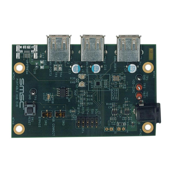
USB3503 Evaluation Board User Manual
Insert EVB graphic/photo
on master page
(this text can be removed on master page)
Copyright © 2013 SMSC or its subsidiaries. All rights reserved.
Circuit diagrams and other information relating to SMSC products are included as a means of illustrating typical applications. Consequently, complete information sufficient for
construction purposes is not necessarily given. Although the information has been checked and is believed to be accurate, no responsibility is assumed for inaccuracies. SMSC
reserves the right to make changes to specifications and product descriptions at any time without notice. Contact your local SMSC sales office to obtain the latest specifications
before placing your product order. The provision of this information does not convey to the purchaser of the described semiconductor devices any licenses under any patent
rights or other intellectual property rights of SMSC or others. All sales are expressly conditional on your agreement to the terms and conditions of the most recently dated
version of SMSC's standard Terms of Sale Agreement dated before the date of your order (the "Terms of Sale Agreement"). The product may contain design defects or errors
known as anomalies which may cause the product's functions to deviate from published specifications. Anomaly sheets are available upon request. SMSC products are not
designed, intended, authorized or warranted for use in any life support or other application where product failure could cause or contribute to personal injury or severe property
damage. Any and all such uses without prior written approval of an Officer of SMSC and further testing and/or modification will be fully at the risk of the customer. Copies of
this document or other SMSC literature, as well as the Terms of Sale Agreement, may be obtained by visiting SMSC's website at http://www.smsc.com. SMSC is a registered
trademark of Standard Microsystems Corporation ("SMSC"). Product names and company names are the trademarks of their respective holders.
The Microchip name and logo, and the Microchip logo are registered trademarks of Microchip Technology Incorporated in the U.S.A. and other countries.
SMSC DISCLAIMS AND EXCLUDES ANY AND ALL WARRANTIES, INCLUDING WITHOUT LIMITATION ANY AND ALL IMPLIED WARRANTIES OF MERCHANTABILITY,
FITNESS FOR A PARTICULAR PURPOSE, TITLE, AND AGAINST INFRINGEMENT AND THE LIKE, AND ANY AND ALL WARRANTIES ARISING FROM ANY COURSE
OF DEALING OR USAGE OF TRADE. IN NO EVENT SHALL SMSC BE LIABLE FOR ANY DIRECT, INCIDENTAL, INDIRECT, SPECIAL, PUNITIVE, OR CONSEQUENTIAL
DAMAGES; OR FOR LOST DATA, PROFITS, SAVINGS OR REVENUES OF ANY KIND; REGARDLESS OF THE FORM OF ACTION, WHETHER BASED ON CONTRACT;
TORT; NEGLIGENCE OF SMSC OR OTHERS; STRICT LIABILITY; BREACH OF WARRANTY; OR OTHERWISE; WHETHER OR NOT ANY REMEDY OF BUYER IS HELD
TO HAVE FAILED OF ITS ESSENTIAL PURPOSE, AND WHETHER OR NOT SMSC HAS BEEN ADVISED OF THE POSSIBILITY OF SUCH DAMAGES.
SMSC USB3503 EVB
Revision 1.0 (05-06-13)
USER MANUAL
Advertisement
Table of Contents

Subscribe to Our Youtube Channel
Related Manuals for SMSC USB3503


Summary of Contents for SMSC USB3503
-
Page 1: User Manual
Any and all such uses without prior written approval of an Officer of SMSC and further testing and/or modification will be fully at the risk of the customer. Copies of this document or other SMSC literature, as well as the Terms of Sale Agreement, may be obtained by visiting SMSC’s website at http://www.smsc.com. -
Page 2: Operation
Initial Bring Up The USB3503 EVB has a default configuration that allows it to operate as a stand alone hub. To begin, connect the U.FL connectors to the HSIC host. Then, plug the evaluation board into the 5V power supply. - Page 3 Figure 3.1 Block Diagram of the USB3503 EVB HSIC and USB Ports The downstream USB ports are mounted on the edges of the USB3503 EVB. The downstream ports use the standard USB Type A receptacle. The label for the port is located near the receptacle. The HSIC upstream port uses U.FL connectors for Data and Strobe.
-
Page 4: Configuration Resistors
USB3503 EVB - Evaluation Board User Manual Test Points, Switches and LEDs There are multiple test points to confirm that the USB3503 EVB is powered properly. TP1 and TP6 connect to GND, TP2 connects to the VBAT pin, and TP3 connects to the VDD_CORE_REG pin. - Page 5 To provide external power to the VDD_CORE_REG pin remove R8 and supply the power through TP3. The USB3503 can function with a single power supply; to do this remove R8 and place a 0Ohm resistor on R9. This connects the VDD_CORE_REG pin to the VDD33_BYP pin allowing the USB3503’s internal 3.3V regulator to supply the VDD_CORE_REG voltage.
- Page 6 USB3503 EVB - Evaluation Board User Manual Below is a summary of the different power options and what resistors need to be populated to support these options: Table 3.2 VBAT and VDD_CORE_REG Source Control VBAT SOURCE VDD_CORE_REG SOURCE INSTALL INSTALL...
- Page 7 USB3503 EVB - Evaluation Board User Manual Below are the locations of the resistors on the back side of the board: Figure 3.5 Regulator Resistors SMSC USB3503 EVB Revision 1.0 (05-06-13) USER MANUAL...
- Page 8 USB3503 EVB - Evaluation Board User Manual 4 Software The USB3503 EVB comes with a CD that contains evaluation software that can be used with the Total Phase Aardvark USB-I C adaptor (not included with the Evaluation Kit). To install the software, run Setup.exe, found on the CD.
-
Page 9: Digital Control
Set the RESET_N pin low to reset the part and place it into the lowest power state. If the CONNECT pin is low when the RESET pin transitions from low to high, the USB3503 will remain in a state that allows the serial interface registers to be manipulated. - Page 10 Write button to change the value on the part. Click on the Read button and the Value and Bit boxes will update the current value on the part. Refer to the USB3503 datasheet for a detailed description of each register and operation of the device...
- Page 11 USB3503 EVB - Evaluation Board User Manual To change these values; update the configuration section to the desired options, then press the Configure button. The part will then reset, pull the CONNECT pin low and update the registers as specified. To go with these options either raise the CONNECT pin, or press the Connect button.
- Page 12 USB3503 EVB - Evaluation Board User Manual 5 USB3503 EVB Schematic Figure 5.1 USB3503 EVB Schematic Revision 1.0 (05-06-13) SMSC USB3503 EVB USER MANUAL...
- Page 13 USB3503 EVB - Evaluation Board User Manual 6 USB3503 EVB Bill of Materials Figure 6.1 USB3503 EVB Bill of Materials SMSC USB3503 EVB Revision 1.0 (05-06-13) USER MANUAL...
- Page 14 USB3503 EVB - Evaluation Board User Manual 7 User Manual Revision History Table 7.1 Customer Revision History REVISION LEVEL & DATE SECTION/FIGURE/ENTRY CORRECTION Rev. 1.0 (05-06-13) Co-branded document Rev. 1.0 (09-12-11) Document release Revision 1.0 (05-06-13) SMSC USB3503 EVB USER MANUAL...
Need help?
Do you have a question about the USB3503 and is the answer not in the manual?
Questions and answers