Table of Contents
Advertisement
Quick Links
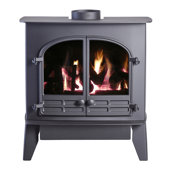
SELENE
6 D
GAS STOVE
Installation and Servicing Instructions
Please leave this instruction booklet with the user after the installation is
complete. Leave the system ready for operation and instruct the user in
the correct use of the appliance and operation of its controls.
Please refer to the appliance data plate for the specific model type.
RevE 18/02/14
1
Advertisement
Table of Contents

Subscribe to Our Youtube Channel
Related Manuals for Hunter Stoves HS Gas SELENE 6 D


Summary of Contents for Hunter Stoves HS Gas SELENE 6 D
- Page 1 SELENE GAS STOVE Installation and Servicing Instructions Please leave this instruction booklet with the user after the installation is complete. Leave the system ready for operation and instruct the user in the correct use of the appliance and operation of its controls. Please refer to the appliance data plate for the specific model type.
-
Page 2: Table Of Contents
Contents TECHNICAL DATA ..........3 STOVE DIMENSIONS ......................4 INSTALLING THE APPLIANCE ......4 ......................4 NSTALLATION OTES ........................6 RRANGEMENT ) ...................6 (GB O DDITIONAL ENTING ...................... 7 EMOVING THE TOVE ................................8 Removing the Glass ......................8 UPPLY ONNECTIONS ...................... -
Page 3: Technical Data
TECHNICAL DATA NATURAL GAS Nominal Gas Pressure 20mBar 37mBar Supply Gas Type/Category G20/I G31/I Jet Type/Size 82/380 92/190 Heat Input (Gross) Full 6.5kW 6.4 kW 4.2kW 3.7 kW Gas Flow Rate (m Full 0.62 m 0.236 m NOx Class Efficiency Class Countries of Destination GB &... -
Page 4: Stove Dimensions
STOVE DIMENSIONS: Diagram 1 INSTALLING THE APPLIANCE Pre-Installation Notes 1. Check the stove data plate to establish the gas type required. The data plate can be found on a chain at the top left rear corner of the stove. Before installation check that the local distribution conditions, nature of the gas and pressure, and adjustment of the application are compatible. - Page 5 7. The hearth should be edged or raised to prevent combustible floor finishes (e.g. Carpet) from being laid too close to the appliance. 8. Opening clearances For the relevant clearance distances when installing the appliance in an opening see diagram 2 below: Diagram 2 MINIMUM CLEARANCE DISTANCES TO: DIMENSION...
-
Page 6: Flue Arrangement
Flue Arrangement The GAS SAFE REGISTERED ENGINEER commissioned to install this appliance is wholly responsible for deciding the suitability of any flue arrangement to operate in conjunction with this gas appliance. The chimney or flue system that is to be fitted to the Selene gas stove must comply with the current rules in force. -
Page 7: Removing The Stove Body
Removing the Stove Body Open the two cast iron doors and gently lift them from their hinges as shown in Diagram 3. Diagram 3 Completely remove the 2 securing bolts that are located behind the valve cover plate by using a 10mm spanner, as shown in Diagram 4. Diagram 4 Slacken the rear locating bolts with a 13mm spanner and remove the stove shell by sliding away from the combustion chamber. -
Page 8: Removing The Glass
Removing the Glass The glass is held in place by 6 fixing clips, 4 at the top and 2 at the bottom. Slightly slacken the lower two fixing screws with a flat blade screwdriver (There is no need to fully remove the screws). Holding the glass with one hand, slacken off the top 2 fixing screws (Diagram 6) until the clips have moved away from the glass panel. -
Page 9: Testing Supply Pressure
Testing Supply Pressure 1. Gas pressure at the appliance is measured via the rearward test nipple (Test nipple ‘A’ in diagram 8) on the left-hand side of the control valve. (Turning the screw approximately half a turn anti-clockwise with a small flat-bladed screwdriver opens the test point.) ALWAYS CLOSE TEST POINTS AFTER USE! 2. -
Page 10: Installation Of The Fire-Bed Into The Stove
INSTALLATION OF THE FIRE-BED INTO THE STOVE IMPORTANT NOTE!! CERAMIC COALS AND LOGS GET VERY HOT! NEVER ATTEMPT TO HANDLE HOT COALS OR LOGS WITH BARE HANDS AND NEVER PLACE HOT COALS OR LOGS ON OR NEAR COMBUSTIBLE SURFACES. NO RESPONSIBILITY FOR ANY INJURY HOWEVER CAUSED WHILST HANDLING HOT COALS, LOGS OR CERAMICS CAN BE ACCEPTED BY HS GAS. -
Page 11: Fitting The Loose Ceramic Coals
3. Place the front ceramic matrix into the fire so that it sits between the middle ceramic matrix and the 2 front tray supports (Steel brackets at the front of the tray) shown in diagram A11. Diagram A11 Fitting the Loose Ceramic Coals 4. - Page 12 6. The third row of coals consists of 6 medium sized coals (6 small coals for LPG stoves). The coals are placed so that they sit on top of the last row of coals and into the notches on the rear ceramic matrix, shown in Diagram A14.
-
Page 13: Section B - Fitting The Log Effect Ceramic Matrices
Section B - Fitting the Log Effect Ceramic Matrices The fire-bed is constructed of 3 ceramic matrices and 6 loose logs. A. Place the rear ceramic matrix into the fire as shown in diagram B9. The ceramic should sit on the burner tray top and be placed so that it touches the back of the firebox. -
Page 14: Fitting The Loose Ceramic Logs
Fitting the Loose Ceramic Logs D. Starting with the Y-shaped log, place at the angle shown in diagram B12. The bottom of the log should sit in the cut-out on the front ceramic matrix, with the flat underside of it resting on the flat area on the middle matrix. - Page 15 G. The fourth log is the shorter of the two straight logs. The log should rest on the middle ceramic on the flat section to the right of the large log. The top of the log should rest in the groove on the rear ceramic, as shown in diagram B15.
-
Page 16: Re-Assembling The Stove
Re-Assembling the Stove When the desired flame picture has been achieved, the stove body should be reassembled. The stove body can be slid back into place, making sure that the slots on the rear of the body locate into the 2 securing bolts at the back of the base, shown in diagram 5 (Page 7). -
Page 17: Operating The Appliance
Operating the Appliance ULL OPERATING INSTRUCTIONS ARE GIVEN IN THE NSTRUCTIONS Fitting the Remote Control (Optional) Fitting the Motor to the Valve Un-screw the cover retaining screw with a small Philips screwdriver (Shown in diagram 19). Prise off the cover at the snap connection with a small flat-bladed screwdriver located on the right hand side of the valve. -
Page 18: Attaching The Remote Control Receiver Box
Attaching the Remote Control Receiver Box The control lead is then attached to the receiver box using the plastic connector and to the valve motor by the two spade terminals. The Remote Control Receiver Box is powered by 4 x AA batteries (supplied). The batteries are fitted by sliding the cover off the receiver box the orientation of the batteries shown on the diagram in the box. -
Page 19: Servicing Instructions
SERVICING INSTRUCTIONS It must be understood that any recommendations made here are in addition to the standard servicing procedures used by the servicing engineer. 1. A GAS SAFE registered fitter using only original HS GAS parts should carry out servicing. 2. -
Page 20: Spares List
SPARES LIST PART DESCRIPTION PART NUMBER Bundy Tube – Main Burner HG06/032 Bundy Tube – Pilot HG06/033 Bundy Tube Inlet HG06/034 TTB Switch HG06/200 TTB Leads HG06/201 Nat. Gas Burner Injector HG01BU024 LPG Burner Injector HG06083 Flue Collar HG06/038 Flue Blanking Plate HG06/037 Flue Gasket...
Need help?
Do you have a question about the HS Gas SELENE 6 D and is the answer not in the manual?
Questions and answers