Viking VDSC530 Service Manual
Hide thumbs
Also See for VDSC530:
- Manual (48 pages) ,
- Service manual (39 pages) ,
- Use & care manual (36 pages)
Table of Contents
Advertisement
Quick Links
Service
Manual
This manual is to be used by qualifi ed appliance technicians only. Viking
does not assume any responsibility for property damage or personal
injury for improper service procedures done by an unqualifi ed person.
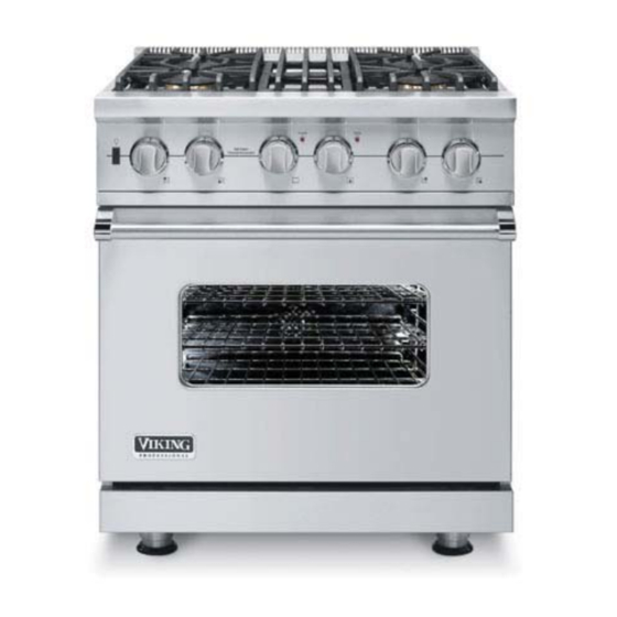
30, 36, & 48 Inch
Dual Fuel Range
Preferred Service
This Base Manual covers general and
specifi c information including, but not
limited to the following models:
December 2009
®
VDSC530
VDSC536
VDSC548
SMC-0003B
Advertisement
Table of Contents

Related Manuals for Viking VDSC530


Summary of Contents for Viking VDSC530
- Page 1 Service Preferred Service Manual This manual is to be used by qualifi ed appliance technicians only. Viking does not assume any responsibility for property damage or personal injury for improper service procedures done by an unqualifi ed person. 30, 36, & 48 Inch This Base Manual covers general and specifi...
-
Page 2: Important Information
All safety messages will be preceded by the safety alert symbol and the word “DANGER”, “WARNING”, or “CAUTION”. These words mean: VIKING will not be responsible for any injury or property damage from improper service procedures. If performing service on your own product, you must... - Page 3 Freestanding dual fuel ranges and all of their component parts, except as detailed below*, are warranted to be free from defective materials or workmanship in normal household use for a period of twelve (12) months from the date of original retail purchase. Viking Range Corporation, warrantor, agrees to repair or replace, at its option, any part which fails or is found to be defective during the warranty period.
-
Page 4: Table Of Contents
Strip Circuits ............48 Motor Capacitor Removal ........29 Electronic Thermostat - DSI System Door Assembly Removal ........29 (VDSC536-4G, VDSC548-6G, & VDSC548-4GQ) 50 Door Gasket Removal ..........29 Wiring Diagrams ............ 51 Door Handle Removal ..........30 ©2009 Viking Preferred Service... -
Page 5: General Information
8 ” 26-7/16” (67.2 cm) - 7 / ( 7 5 8 ” 8-1/8” 1” (20.6 cm) (2.5 cm) 35-7/8” (91.1 cm) min. 37” (94 cm) max. 19-3/8” 25-3/4” (49.2 cm) (65.4 cm) 45-1/8” (114.6 cm) ©2009 Viking Preferred Service... -
Page 6: Specifi Cations
• Wall cabinets directly above product must be a minimum of 42" (106.7 cm) above cooking surface • Rear - 0" with 8" backguard or high shelf; 0" with island trim and noncombustible rear wall; • 6" (15.2 cm) with island trim and combustible rear wall ©2009 Viking Preferred Service... -
Page 7: Warnings
Some cleaners can produce noxious To Prevent Fire or Smoke Damage fumes if applied to a hot surface. • Be sure all packing materials are removed from the appliance before operating it. ©2009 Viking Preferred Service... -
Page 8: Self-Clean Oven
Danger of burning: DO NOT touch the glass! • For proper oven performance and operation, DO NOT block or obstruct the oven vent duct located on the right side of the air grille. ©2009 Viking Preferred Service... -
Page 9: Electrical & Gas Requirements
Children climbing to reach items could be seriously injured. GAS LEAKS. Connect gas and electrical. Before placing appliance in operation, always check for gas leaks. This must be performed by your dealer, a qualifi ed licensed plumber, or gas service company. ©2009 Viking Preferred Service... -
Page 10: In Massachusetts
10 minutes with oven racks inside oven. This could cause them to discolor due to In Massachusetts the high temperature required for self-cleaning. This appliance must be installed with a 36" (3-foot) long fl exible gas connector. ©2009 Viking Preferred Service... -
Page 11: Before Using Range
• This appliance is certifi ed by Star-K to meet strict 10. Center grate regulations in conjunction with specifi c instructions 11. Identifi cation plate found on www.star-k.org. 12. Two standard heavy-duty tilt-proof racks/One heavy- duty TruGlide rack. Six rack positions 13. Broiler pan–located inside oven ©2009 Viking Preferred Service... -
Page 12: Inch Model
2. Island trim 3. Grill (Optional) 48” Six-Burner/Grill 48” Four-Burner/Grill/Griddle 4. Griddle (Optional) 5. Identifi cation plate 6. Three standard heavy-duty tilt-proof racks. Six rack positions 7. Broiler pan–located inside oven ©2009 Viking Preferred Service... -
Page 13: Troubleshooting
LED Error Codes Type of error Cycle Light 2 fl ashes, then 4 seconds OFF (Griddle Probe) Griddle Control Connections The griddle control is only on the following models: VDSC536-4G, VDSC548-6G, and VDSC548-4GQ. ©2009 Viking Preferred Service... -
Page 14: Fault Codes For Dsi Boards
Gas solenoid fault. Check wiring and gas solenoid. 7 fl ashes every 4 seconds Power up with channel on. Switch channel off and retry. 8 fl ashes every 4 seconds Gas solenoid fault. Check wiring and gas solenoid. Direct Spark Module Connections ©2009 Viking Preferred Service... -
Page 15: Led Error Codes
1 second ON, 1 second OFF 1 second ON, 1 second OFF (Oven Probe) Model 1 second ON, 1 second OFF, 1 second ON, 4 seconds OFF Cooling Fan 3 fl ashes High Limit 4 fl ashes Oven Control Board Connections ©2009 Viking Preferred Service... -
Page 16: Oven Components
Open or out of calibration thermostat Replace thermostat Open relay K12, K13, K14, K5, K6, Replace control board or K7 Open control board Replace control board Defective oven wiring (shorted, Repair or replace defective wiring open, or burned) ©2009 Viking Preferred Service... - Page 17 Repair or replace defective wiring open, or burned) Oven lights inoperable (bulbs OK) Open control board Replace control board Open relay K4 Replace control board Defective oven wiring (shorted, Repair or replace defective wiring open, or burned) ©2009 Viking Preferred Service...
- Page 18 Griddle cycle light inoperable - RH Defective cycle light (neon) Replace cycle light oven, LH oven, surface burner, grill, Open griddle control Replace griddle control and griddle igniters operate Defective oven wiring (shorted, Repair or replace defective wiring open, or burned) ©2009 Viking Preferred Service...
-
Page 19: Selector And Thermostat Characteristics
0.70 VDC 9.22 k 4.30 VDC Resistance checks are made on the thermostat wire harness with the thermostat wire harness disconnected from the board at location P15. The harness is connected to P15 for voltage checks. ©2009 Viking Preferred Service... -
Page 20: Component Characteristics
ON (Door Closed) Oven Door Switch 0 VDC Open (P20 brown - purple) P20 brown - purple (Door Open) Oven Door Switch 16 VDC Open (P20 brown - purple) (P20 P20 brown - purple (Door Closed) disconnected) ©2009 Viking Preferred Service... -
Page 21: Checking Convection Element Operation
P2 white to P1 black? Disconnect power to the range. Check convection element resistance. 240 VAC present K17 yellow to P2 white? Convection element 19.0 ? Repair or replace Replace convection Replace control board. element. defective wiring. ©2009 Viking Preferred Service... -
Page 22: Checking Lh Oven Bake Element Operation
P5 orange to P1 black? Disconnect power to the range. Check bake element resistance. 240 VAC present K17 yellow to P5 orange? Bake element 32.4 ? Repair or replace Replace control board. Replace bake element. defective wiring. ©2009 Viking Preferred Service... -
Page 23: Checking Rh Oven Bake Element Operation
Inner bake element 39.0 ? 240 VAC present K17 yellow to P5 blue? Outer bake element 38.0 ? 240 VAC present K17 yellow to P5 orange? Repair or replace Replace control board. Replace bake element. defective wiring. ©2009 Viking Preferred Service... -
Page 24: Checking Lh Oven Broil Element Operation
Inner broil element 39.3 ? 240 VAC present K17 yellow to P6 grey? Outer broil element 43.7 ? 240 VAC present K17 yellow to P6 purple? Repair or replace Replace control board. Replace broil element. defective wiring. ©2009 Viking Preferred Service... -
Page 25: Checking Rh Oven Broil Element Operation
Inner broil element 29.3 ? 240 VAC present K17 yellow to P6 grey? Outer broil element 33.0 ? 240 VAC present K17 yellow to P6 purple? Repair or replace Replace control board. Replace broil element. defective wiring. ©2009 Viking Preferred Service... -
Page 26: Checking Griddle Operation
(Gas supply valve in open position.) Disconnect power to range. Replace griddle Check griddle solenoid resistance. solenoid valve. 210 present S1 brown to SC blue? ©2009 Viking Preferred Service... -
Page 27: Spark Module Test
RTD. If the RTD test resistance is within specifi cations and the consumer is having erratic oven temperatures, please call Viking 7. Remove the grate, burner cap, and burner head. Technical support (1-800-914-4799) for assistance. -
Page 28: Disassembly
3. Remove ten screws and control board from lower mounting plate. Note: During installation, make sure the tabs on the control panel are aligned with the slots on the range. 4. Reverse procedure for installation. 4. Reverse procedure for installation. ©2009 Viking Preferred Service... -
Page 29: Motor Capacitor Removal
3. Close door until pins stop door. 2. Remove the door gasket from two holes in the bottom of the door liner. 3. Reverse procedure for installation. ©2009 Viking Preferred Service... -
Page 30: Door Handle Removal
1. Place the door handle side down on a protected surface. 2. Remove seven screws that attach the outer door panel assembly to the inner door panel assembly. 3. Remove door skin insulation from door skin. ©2009 Viking Preferred Service... -
Page 31: Inner Door Glass Removal
4. Remove black fi berglass rope from inner door panel. 8. Reverse procedure for installation. Note: Use care with insulation, make sure to replace any damaged or missing insulation. Keep vent on inner door panel clear of insulation. 5. Reverse procedure for installation. ©2009 Viking Preferred Service... -
Page 32: Door Hinge Removal
Outer Door Panel Assembly Removed into place. 1. Remove two pal nuts and logo from outer door panel. 2. Reverse procedure for installation. 5. Install two screws that attach the sensor to the back of the oven liner. ©2009 Viking Preferred Service... -
Page 33: Bake Element Removal
1. Remove screws and rack support from each side of oven cavity. 4. Remove bake element insulation from range. Note: Use care with insulation, make sure to replace any damaged or missing insulation. 2. Reverse procedure for installation. ©2009 Viking Preferred Service... -
Page 34: Convection Fan Cover Removal
2. Pull down the smoke eliminator to remove from oven liner. 3. Reverse procedure for installation. Note: The mounting hole pattern for the convection fan assembly is NOT symmetrical. Line up holes before installing. 3. Reverse procedure for installation. ©2009 Viking Preferred Service... -
Page 35: Convection Bake Element Removal
2. Remove four screws and front broil element bracket Control Panel Assembly Removal from oven cavity. Condition Requirements: Door Lowered 1. Remove all knobs. 2. Remove four screws and bezels from control panel assembly. 3. Remove two screws from control panel assembly. ©2009 Viking Preferred Service... -
Page 36: Oven Function Selector Removal
Control Panel Assembly Removed 1. Disconnect connector from the oven function selector. 2. Remove two screws, bezel, and the oven function selector from the control panel assembly. 3. Reverse procedure for installation. 3. Reverse procedure for installation. ©2009 Viking Preferred Service... -
Page 37: Oven Light Bulb Removal
Control Panel Assembly Removed 1. Disconnect two connectors from the light switch. 2. Press tabs on both ends of the switch and push switch through control panel. 4. Reverse procedure for installation. 3. Reverse procedure for installation. ©2009 Viking Preferred Service... -
Page 38: Indicator Lights Removal
Condition Requirements: Control Panel Assembly Removed 1. Remove two screws and door switch from range. 2. Mark and disconnect two connectors from door switch. 4. Reverse procedure for installation. 3. Reverse procedure for installation. ©2009 Viking Preferred Service... -
Page 39: Iris Module Removal
Griddle Burner Igniter Removal (VDSC536-4G, VDSC548-6G, & VDSC548-4GQ) Condition Requirements: 4. Reverse procedure for installation. Griddle Plate and Drip Pan Removed 1. Remove two screws and igniter from range. 2. Disconnect wire from igniter. 3. Reverse procedure for installation. ©2009 Viking Preferred Service... -
Page 40: Direct Spark Module Removal
2. Pull to remove module from burner valve. 3. Remove fl ex tubing from burner valve. 4. Remove screw and burner valve from manifold assembly. 4. Reverse procedure for installation. 5. Reverse procedure for installation. 6. Perform gas leak test. ©2009 Viking Preferred Service... -
Page 41: Island Trim Removal
2. Place backguard assembly on suitable work surface. 3. Remove 17 screws and back. Note: Pry corner of front panel slightly to allow front support to slide from the front panel. 7. Reverse procedure for installation. 4. Remove inner diverter. ©2009 Viking Preferred Service... -
Page 42: Main Top Removal
4. Remove fl ex tubing from jet holder. 5. Remove screw and top support from range. 5. Remove two screws and side trim from each side of range. 6. Reverse procedure for installation. 7. Perform gas leak test. ©2009 Viking Preferred Service... -
Page 43: Manifold Assembly Removal
Condition Requirements: None 1. Remove grates, burner cap, and burner head from burner base assembly. 2. Remove orifi ce from jet holder. 4. Reverse procedure for installation. 5. Perform gas leak test. 3. Reverse procedure for installation. ©2009 Viking Preferred Service... -
Page 44: Burner Base Assembly Removal
Hinge Receiver Removal Condition Requirements: Door Assembly Removed Side Panel Removed 1. Remove three screws and side trim from range. 2. Remove fi ve screws and panel from range. 2. Remove two screws and side trim from range. ©2009 Viking Preferred Service... -
Page 45: Back Panel Removal
2. Remove four screws and blower mount from range. 3. Mark and disconnect three connectors and remove blower motor. 2. Remove three screws and rear wiring channel from range. 3. Remove 12 screws and back panel from range. 4. Reverse procedure for installation. ©2009 Viking Preferred Service... -
Page 46: Terminal Block Removal
Ensure all ground wires are connected before certifying unit as repaired and/or operational. Terminal Block Removal Condition Requirements: Back Panel Removed 1. Mark and disconnect all connectors from terminal block. 2. Remove three screws and terminal block from range. 3. Reverse procedure for installation. ©2009 Viking Preferred Service... -
Page 47: Wiring Diagrams
Light Selector Cycle Selector Probe Convection Fan Power Outer Convection Broil Fan Direction Convection Inner Fan Speed Broil Cool Fan Speed Outer Bake Model Header Inner Bake Second Board Seriel Com Status Door Light Door Lock ©2009 Viking Preferred Service... -
Page 48: Strip Circuits
BREAK RELAY BLUE WHT YEL (30", 36", & 48" RH Oven) 38.0 (48" LH Oven) NOT EQUIPPED INNER BAKE ELEMENT LINE RELAY BREAK RELAY WHT YEL (30", 36", & 48" RH Oven) 39.0 (48" LH Oven) 32.4 ©2009 Viking Preferred Service... - Page 49 POWER RELAY 2.0 ufd 2.0 ufd CONVECTION BLUE BROWN DIRECTION RELAY GREY ORANGE CONVECTION GREEN SPEED RELAY BOARD CIRCUIT COOLING BLOWER MOTOR WHITE WHITE 18.2 WHITE BOARD CIRCUIT DOOR LATCH MOTOR WHITE BLACK BOARD 12.1 k CIRCUIT ©2009 Viking Preferred Service...
-
Page 50: Electronic Thermostat - Dsi System
Wiring Diagrams Electronic Thermostat - DSI System (VDSC536-4G, VDSC548-6G, & VDSC548-4GQ) Griddle Control Thermostat and DSI Module System ©2009 Viking Preferred Service... -
Page 51: Wiring Diagrams
Wiring Diagrams Wiring Diagrams VDSC530 Dual Fuel Range ©2009 Viking Preferred Service... - Page 52 Wiring Diagrams VDSC536 Dual Fuel Range ©2009 Viking Preferred Service...
- Page 53 Wiring Diagrams VDSC548 Dual Fuel Range ©2009 Viking Preferred Service...