KTM 1190 RC8 R Owner's Manual
2014
Hide thumbs
Also See for 1190 RC8 R:
- Repair manual (460 pages) ,
- Owner's manual (283 pages) ,
- Owner's manual (281 pages)

Related Manuals for KTM 1190 RC8 R


Summary of Contents for KTM 1190 RC8 R
- Page 1 2014 OWNER'S MANUAL 1190 RC8 R EU/GB 1190 RC8 R FR 1190 RC8 R JP Art. no. 3213111en...
- Page 3 KTM accepts no liability for delivery options, deviations from illustrations and descriptions, as well as misprints and other errors.
- Page 4 DEAR KTM CUSTOMER ISO 9001(12 100 6061) According to the international quality management standard ISO 9001, KTM uses quality assurance processes that lead to the maximum possible quality of the products. Issued by: TÜV Management Service KTM-Sportmotorcycle AG 5230 Mattighofen, Austria...
-
Page 5: Table Of Contents
TABLE OF CONTENTS Steering damper part number......22 TABLE OF CONTENTS MEANS OF REPRESENTATION ........8 CONTROLS..............23 Symbols used ............8 Clutch lever............23 Formats used............8 Hand brake lever..........23 SAFETY ADVICE.............. 9 Throttle grip ............24 Use definition - intended use ........ 9 Horn button............ - Page 6 TABLE OF CONTENTS 6.11.16 Overview of RACE mode ......... 46 6.11.41 External temperature display menu, OPTION OUTTEMP ........74 6.11.17 Remaining laps menu, LAPSTOGO ....47 6.11.42 Tire pressure monitor menu, OPTION TPMS ..75 6.11.18 Maximum lap speed menu, TOPSPEED.... 48 6.11.43 Table of functions..........
- Page 7 TABLE OF CONTENTS 6.17 Passenger footrests .......... 100 10.7 Adjusting the high-speed compression damping of the shock absorber ........126 6.18 Shift lever ............100 10.8 Adjusting the rebound damping of the shock 6.19 Foot brake lever ..........101 absorber............127 6.20 Side stand............
- Page 8 TABLE OF CONTENTS 11.4 Taking the motorcycle off of the front wheel 13 WHEELS, TIRES ............179 stand .............. 157 13.1 Removing the front wheel ......179 11.5 Bleeding fork legs ..........158 13.2 Installing the front wheel ......180 11.6 Removing the seat ...........
- Page 9 TABLE OF CONTENTS 17.2 Changing engine oil and filter, cleaning oil 23.9 Chassis tightening torques ........ 253 screen ............218 24 SUBSTANCES ............257 17.3 Draining engine oil, cleaning oil screens ..218 25 AUXILIARY SUBSTANCES ........... 261 17.4 Removing the oil filter .........
-
Page 10: Means Of Representation
All work marked with this symbol requires specialist knowledge and technical understanding. In the interest of your own safety, have these jobs performed by an authorized KTM workshop. There, your motorcycle will be optimally cared for by specially trained experts using the specialist tools required. -
Page 11: Safety Advice
SAFETY ADVICE Use definition - intended use KTM sport motorcycles are designed and constructed to meet the normal demands of regular road operation and also for use on race courses, but not for offroad use. Info The motorcycle is only authorized for operation on public roads in the homologated version. -
Page 12: Degrees Of Risk And Symbols
SAFETY ADVICE Degrees of risk and symbols Danger Identifies a danger that will immediately and invariably lead to fatal or serious permanent injury if the appropriate measures are not taken. Warning Identifies a danger that is likely to lead to fatal or serious injury if the appropriate measures are not taken. Caution Identifies a danger that may lead to minor injuries if the appropriate measures are not taken. -
Page 13: Safe Operation
The vehicle should only be used by trained persons. An appropriate driver's license is needed to ride the vehicle on public roads. Have malfunctions that impair safety promptly eliminated by an authorized KTM workshop. Adhere to the information and warning labels on the vehicle. -
Page 14: Protective Clothing
Wear protective clothing (helmet, boots, gloves, pants and jacket with protectors) every time you ride the vehicle. Always wear protective clothing that is in good condition and meets the legal requirements. In the interest of your own safety, KTM recommends that you only operate the vehicle while wearing protective clothing. Work rules Special tools are necessary for certain tasks. -
Page 15: Owner's Manual
Keep the Owner's Manual in an accessible place to enable you to refer to it as needed. If you would like to know more about the vehicle or have questions on the material you read, please contact an authorized KTM dealer. -
Page 16: Important Notes
Guarantee, warranty The work prescribed in the service schedule must be carried out by an authorized KTM workshop only and confirmed in the customer's Service & Warranty Booklet and in the KTM dealer.net; otherwise, all warranty claims will be void. No warranty claims can be considered for damage resulting from manipulations and/or alterations to the vehicle. -
Page 17: Figures
Please follow the instructions in the text. Customer service Your authorized KTM dealer will be happy to answer any questions you may have on your vehicle and KTM. A list of authorized KTM dealers can be found on the KTM website. -
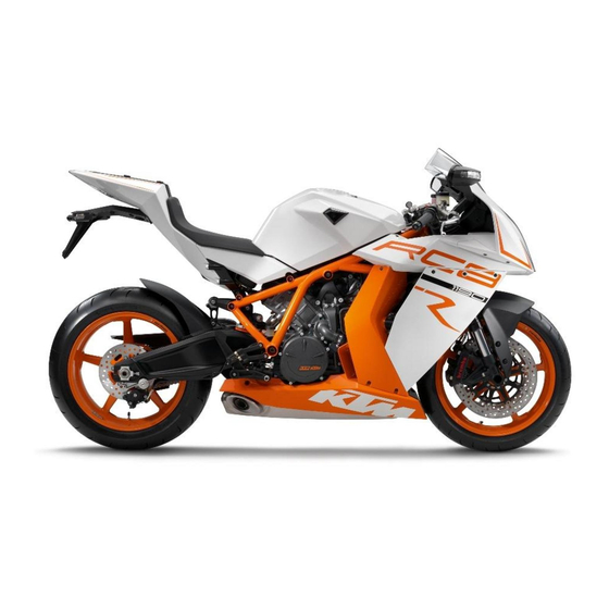
Page 18: View Of Vehicle
VIEW OF VEHICLE View of vehicle, front left (example) B01301-10... - Page 19 VIEW OF VEHICLE Clutch lever ( p. 23) Light switch ( p. 25) Headlight flasher switch ( p. 25) Turn signal switch ( p. 26) Horn button ( p. 24) Filler cap Tool set ( p. 99) Seat lock ( p.
-
Page 20: View Of Vehicle, Rear Right (Example)
VIEW OF VEHICLE View of vehicle, rear right (example) B01302-10... - Page 21 VIEW OF VEHICLE Passenger seat Supporting strap ( p. 99) Fork rebound adjustment Indicator lamps ( p. 33) Ignition/steering lock ( p. 27) Emergency OFF switch ( p. 26) Electric starter button ( p. 27) Hand brake lever ( p. 23) Vehicle identification number/type label ( p.
-
Page 22: Serial Numbers
SERIAL NUMBERS Vehicle identification number/type label The vehicle identification number is stamped on the frame behind the steering head on the right. The type label is on the frame above the vehicle identification number. B01303-10 Key number The key number Code number can be found on the KEYCODECARD. -
Page 23: Engine Number
SERIAL NUMBERS Engine number The engine number is stamped on the right side of the engine. B01304-10 Fork part number The fork part number is stamped on the inner side of the fork stub. B01305-10... -
Page 24: Shock Absorber Part Number
SERIAL NUMBERS Shock absorber part number The shock absorber part number is stamped on the upper part of the shock absorber above the adjusting ring towards the rear. 100657-10 Steering damper part number The steering damper part number is stamped on the top of the steering damper. -
Page 25: Controls
CONTROLS Clutch lever The clutch lever is fitted on the left side of the handlebar. The clutch is hydraulic and self-adjusting. 100659-10 Hand brake lever The hand brake lever is fitted on the right side of the handlebar. The hand brake lever operates the front brake. -
Page 26: Throttle Grip
CONTROLS Throttle grip The throttle grip is fitted on the right side of the handlebar. B00568-10 Horn button The horn button is fitted on the left side of the handlebar. Possible states • Horn button in neutral position pressed –... -
Page 27: Light Switch
CONTROLS Light switch The light switch is fitted on the left side of the handlebar. Possible states Low beam on – The light switch is in the lower position. In this position, the low beam and tail light are switched on. High beam on –... -
Page 28: Turn Signal Switch
CONTROLS Turn signal switch The turn signal switch is fitted on the left side of the handlebar. Possible states Turn signal off Left turn signal on – The turn signal switch is pressed to the left. The turn signal switch automatically returns to the central position after use. Right turn signal on –... -
Page 29: Electric Starter Button
CONTROLS Electric starter button The electric starter button is fitted on the right side of the handlebar. Possible states • Electric starter button in neutral position pressed – In this position, the electric starter is operated. • Electric starter button 100664-11 6.10 Ignition/steering lock... -
Page 30: Combination Instrument
CONTROLS 6.11 Combination instrument 6.11.1 Overview Display ( p. 31) Function buttons Indicator lamps ( p. 33) Info display ( p. 32) 401121-10... -
Page 31: Function Buttons, Handlebar
CONTROLS 6.11.2 function buttons, handlebar The MODE button is fitted on the handlebar, front left. The LAP button is fitted on the handlebar, rear left. MODE button Changes to the next item on the info display in ROAD mode and in RACE mode. LAP button Changes to the next item on the info display in ROAD mode. -
Page 32: Activation And Test
The speed display counts from 0 to 300 and back. The remaining display segments outside the info display light up briefly. The KTM logo appears in the info display. The display then changes to the last selected mode. 401120-01... -
Page 33: Display
CONTROLS 6.11.4 Display The tachometer displays the engine speed in revolutions per minute (RPM). The red marking marks the over-rev (excessive speed) range of the engine. The gear display shows the engaged gear. Info The engaged gear can also be displayed in the info display. The speed ... -
Page 34: Info Display
CONTROLS 6.11.5 Info display The info display has two menus. Menu 1 is ROAD mode (standard) for riding on public roads. Menu 2 is RACE mode for riding on race tracks. It allows riders to time laps themselves. If the general warning lamp lights up, the corresponding message is shown periodically in the info display. -
Page 35: Indicator Lamps
CONTROLS 6.11.6 Indicator lamps Possible states The turn signal indicator lamp flashes green simultaneously with the turn signal – The turn signal is switched on. The oil pressure warning lamp lights up red – The oil pressure is too low. The shift warning lights up/flashes red –... -
Page 36: Immobilizer
The second black ignition key is activated when the vehicle is shipped. Two additional spare ignition keys (key number on the KEYCODECARD) can be ordered from an authorized KTM RC8 workshop, but they must be activated before use. 6.11.8 notes/warnings LOW FUEL appears on the info display if the minimum range falls below the specified value. - Page 37 CONTROLS LOW BATTERY appears on the info display if the battery voltage falls below the specified value. Battery voltage 10.80 V 401124-01 SERVICE IN xxx KM(MPH) appears on the info display if the distance to the next service falls below the specified value. Distance 500 km (310 mi) 401125-01...
- Page 38 CONTROLS ICE appears on the info display if the external temperature falls below the specified value. Temperature 3 °C (37 °F) ICE disappears if the external temperature rises above the specified value. Temperature 4 °C (39 °F) 401127-01...
-
Page 40: Overview Of Road Mode
CONTROLS 6.11.9 Overview of ROAD mode 401128-10... -
Page 41: Distance Menu 1, Odo/Trip 1/Time 1/Avs 1
CONTROLS Functions in ROAD mode Distance menu 1, ODO/Trip 1/Time 1/Avs 1 Distance menu 2, ODO/Trip 2/Time 2/Avs 2 Gear display menu, ODO/Trip 1/Gear Fuel and external temperature menu, FUEL Mapping menu, ENGINE MAP Next service menu, DISTANCE TO Next Service 6.11.10 Distance menu 1, ODO/Trip 1/Time 1/Avs 1 Condition Alternative 1... -
Page 42: Distance Menu 2, Odo/Trip 2/Time 2/Avs 2
CONTROLS Press the button No function Press the button No function Press the button The display changes to the SET‑UP menu and the button 3 - 5 seconds. Press the MODE but- The display of Trip 1, Time 1 and Avs 1 is reset ton for 3 - 5 sec- onds. -
Page 43: Gear Display Menu, Odo/Trip 1/Gear
CONTROLS The calculation of this value starts with the first speed signal and ends 3 seconds after the last speed signal. Avs 2 shows the average speed and is coupled with Trip 2 and Time 2. Press the button No function Press the button No function Press the button... - Page 44 CONTROLS Trip 1 shows the distance covered since the last reset. For example, between two refueling stops. Trip 1 is always running and counts up to 9999.9. Gear shows the gear currently engaged. Press the button No function Press the button No function Press the button The display changes to the SET‑UP menu...
-
Page 45: Fuel And External Temperature Menu, Fuel
CONTROLS 6.11.13 Fuel and external temperature menu, FUEL Condition Alternative 1 • The ignition is on. • The motorcycle is stationary. • ROAD mode Alternative 2 • The ignition is on. • The motorcycle is being ridden. • ROAD mode –... -
Page 46: Mapping Menu, Engine Map
CONTROLS Press the MODE but- Next display mode ton briefly. 6.11.14 Mapping menu, ENGINE MAP Condition Alternative 1 • The ignition is on. • The motorcycle is stationary. • ROAD mode Alternative 2 • The ignition is on. • The motorcycle is being ridden. •... -
Page 47: Next Service Menu, Distance To Next Service
CONTROLS 6.11.15 Next service menu, DISTANCE TO Next Service Condition • The ignition is on. • The motorcycle is stationary. ROAD mode • – Press the MODE button briefly and repeatedly until DISTANCE TONext Service appears in the info display. DISTANCE TO Next Service shows the distance before the next service is necessary. -
Page 48: Overview Of Race Mode
CONTROLS 6.11.16 Overview of RACE mode 401142-10... -
Page 49: Remaining Laps Menu, Lapstogo
CONTROLS Functions in RACE mode Remaining laps menu, LAPSTOGO Maximum lap speed menu, TOPSPEED Gear display menu, LastLap/RaceTrip/Gear Fuel and external temperature menu, FUEL Mapping menu, ENGINE MAP Lap times menu, LAP/BESTLAP/LapTime Maximum speed menu, LAP/BESTLAP/TopSpeed Total distance menu in Race mode RACEODO 6.11.17 Remaining laps menu, LAPSTOGO Condition Alternative 1... -
Page 50: Maximum Lap Speed Menu, Topspeed
CONTROLS LastLap shows the lap time of the last lap. ±Last shows the difference between the last lap and the lap before last. ±Best shows the difference between the last lap and the best lap. If the last lap was the fastest, you see behind ±Best: the Best! symbol in the info display. Press the button No function Press the button... - Page 51 CONTROLS If an R appears after TOPSPEED, the stopwatch is running in the background. If a P appears after TOPSPEED, the stopwatch in the background is active but waiting for a speed signal. The time is not running. This function is controlled with the LAP button. LastLap shows the maximum speed of the last lap.
-
Page 52: Gear Display Menu, Lastlap/Racetrip/Gear
CONTROLS 6.11.19 Gear display menu, LastLap/RaceTrip/Gear Condition Alternative 1 • The ignition is on. • The motorcycle is stationary. • RACE mode Alternative 2 • The ignition is on. • The motorcycle is being ridden. • RACE mode 401145-01 – Press the MODE button briefly and repeatedly until LastLap, RaceTrip, and Gear appear in the info display. -
Page 53: Fuel And External Temperature Menu, Fuel
CONTROLS 6.11.20 Fuel and external temperature menu, FUEL Condition Alternative 1 • The ignition is on. • The motorcycle is stationary. • RACE mode Alternative 2 • The ignition is on. • The motorcycle is being ridden. • RACE mode –... -
Page 54: Mapping Menu, Engine Map
CONTROLS Press the MODE but- Next display mode ton briefly. 6.11.21 Mapping menu, ENGINE MAP Condition Alternative 1 • The ignition is on. • The motorcycle is stationary. • RACE mode Alternative 2 • The ignition is on. • The motorcycle is being ridden. •... -
Page 55: Lap Times Menu, Lap/Bestlap/Laptime
CONTROLS 6.11.22 Lap times menu, LAP/BESTLAP/LapTime Condition • The ignition is on. • The motorcycle is stationary. RACE mode • – Press the MODE button briefly and repeatedly until LAP/BESTLAP/LapTime appears in the info display. LAP shows the selected lap. BESTLAP shows the number of the lap with the best lap time. -
Page 56: Maximum Speed Menu, Lap/Bestlap/Topspeed
CONTROLS 6.11.23 Maximum speed menu, LAP/BESTLAP/TopSpeed Condition • The ignition is on. • The motorcycle is stationary. RACE mode • – Press the MODE button briefly and repeatedly until LAP/BESTLAP/TopSpeed appears in the info display. LAP shows the selected lap. BESTLAP shows the lap in which the highest maximum speed was reached. -
Page 57: Total Distance In Race Mode Menu, Raceodo
CONTROLS 6.11.24 Total distance in Race mode menu, RACEODO Condition • The ignition is on. • The motorcycle is stationary. RACE mode • – Press the MODE button briefly and repeatedly until RACEODO appears at the top of the info display. RACEODO shows the total distance covered in RACE mode. -
Page 58: Overview Of Set-Up Mode
CONTROLS 6.11.25 Overview of SET‑UP mode ODO/Trip 1 ODO/Trip 2 ODO/Trip 1/Gear FUEL ENGINE MAP SHIFT RPMS DISTANCE TO Next Service LAP BLANK TIME CHANGE MODE SET NUM LAPS SET CLOCK LAPSTOGO TRIP F RESET SETTINGS... TOPSPEED ** SET-UP ** BACK... - Page 59 CONTROLS Settings in SET‑UP mode Mode menu, CHANGE MODE Time menu, SET CLOCK Settings menu, SETTINGS Units menu, UNITS Additional functions menu, OPTIONS EXIT SETUP menu...
-
Page 60: Set-Up Menu
CONTROLS 6.11.26 SET‑UP menu Condition Alternative 1 • The ignition is on. • The motorcycle is stationary. • ROAD mode Alternative 2 • The ignition is on. • The motorcycle is stationary. • RACE mode – Press the button and the button for 3 - 5 seconds. -
Page 61: Mode Menu, Change Mode
CONTROLS Press the MODE but- The menu in front of the arrow is selected ton for 3 - 5 sec- onds. Press the MODE but- The menu in front of the arrow is selected ton briefly. 6.11.27 Mode menu, CHANGE MODE Condition Alternative 1 •... -
Page 62: Time Menu, Set Clock
CONTROLS Press the MODE but- Open and exit CHANGE MODE ton briefly. 6.11.28 Time menu, SET CLOCK Condition Alternative 1 • The ignition is on. • The motorcycle is stationary. • ROAD mode Alternative 2 • The ignition is on. •... -
Page 63: Settings Menu
CONTROLS 6.11.29 SETTINGS menu Condition Alternative 1 • The ignition is on. • The motorcycle is stationary. • ROAD mode Alternative 2 • The ignition is on. • The motorcycle is stationary. • RACE mode – Press the button and the button for 3 - 5 seconds. -
Page 64: Shift Warning Lamp Menu, Shift Rpms
CONTROLS Press the MODE but- The menu in front of the arrow is selected ton for 3 - 5 sec- onds. Press the MODE but- The menu in front of the arrow is selected ton briefly. 6.11.30 Shift warning lamp menu, SHIFT RPMS Condition Alternative 1 •... -
Page 65: Lap Button Blank Time, Lap Blank Time Menu
CONTROLS Press the MODE but- Open and exit SHIFT RPMS or change to the next value ton for 3 - 5 sec- onds. Press the MODE but- Open and exit SHIFT RPMS or change to the next value ton briefly. 6.11.31 LAP button blank time, LAP BLANK TIME menu Condition Alternative 1... -
Page 66: Number Of Laps Menu, Set Num Laps
CONTROLS Press the MODE but- Open and exit LAP BLANK TIME ton for 3 - 5 sec- onds. Press the MODE but- Open and exit LAP BLANK TIME ton briefly. 6.11.32 Number of laps menu, SET NUM LAPS Condition Alternative 1 •... -
Page 67: Fuel Reserve Display Menu, Trip F Reset
CONTROLS Press the MODE but- Open and exit SET NUM LAPS ton for 3 - 5 sec- onds. Press the MODE but- Open and exit SET NUM LAPS ton briefly. 6.11.33 Fuel reserve display menu, TRIP F RESET Condition Alternative 1 •... - Page 68 CONTROLS Press the button No function and the button 3 - 5 seconds. Press the MODE but- Open and exit TRIP F RESET ton for 3 - 5 sec- onds. Press the MODE but- Open and exit TRIP F RESET ton briefly.
-
Page 69: Units Menu
CONTROLS 6.11.34 UNITS menu Condition Alternative 1 • The ignition is on. • The motorcycle is stationary. • ROAD mode Alternative 2 • The ignition is on. • The motorcycle is stationary. • RACE mode – Press the button and the button for 3 - 5 seconds. -
Page 70: Kilometers/Miles Menu, Set Km/Miles
CONTROLS Press the MODE but- The menu in front of the arrow is selected ton briefly. 6.11.35 Kilometers/miles menu, SET KM/MILES Condition Alternative 1 • The ignition is on. • The motorcycle is stationary. • ROAD mode Alternative 2 • The ignition is on. -
Page 71: Temperature Display Menu, Set °C/°F
CONTROLS Press the MODE but- Open and exit SET KM/MILES ton briefly. 6.11.36 Temperature display menu, SET °C/°F Condition Alternative 1 • The ignition is on. • The motorcycle is stationary. • ROAD mode Alternative 2 • The ignition is on. •... -
Page 72: Fuel Consumption Menu (Liters), Set Fuel Cons
CONTROLS Press the MODE but- Open and exit SET °C/°F ton briefly. 6.11.37 Fuel consumption menu (liters), SET FUEL CONS Condition • The ignition is on. • The motorcycle is stationary. • The KM/H unit is activated. – Press the button and the button for 3 - 5 seconds. -
Page 73: Fuel Consumption Menu (Gallons), Set Gal Us/Uk
CONTROLS 6.11.38 Fuel consumption menu (gallons), SET GAL US/UK Condition • The ignition is on. • The motorcycle is stationary. The MPH unit is activated. • – Press the button and the button for 3 - 5 seconds. – Press the button three times until the symbol shows UNITS in the info display. -
Page 74: Additional Functions Menu, Options
CONTROLS 6.11.39 Additional functions menu, OPTIONS Condition Alternative 1 • The ignition is on. • The motorcycle is stationary. • ROAD mode Alternative 2 • The ignition is on. • The motorcycle is stationary. • RACE mode 401158-01 – Press the button and the button for 3 - 5 seconds. -
Page 75: Quick Shifter Menu, Option Qkshift
CONTROLS Press the MODE but- The menu in front of the arrow is selected ton briefly. 6.11.40 Quick shifter menu, OPTION QKSHIFT Condition Alternative 1 • The ignition is on. • The motorcycle is stationary. • ROAD mode Alternative 2 •... -
Page 76: External Temperature Display Menu, Option Outtemp
CONTROLS Press the MODE but- Open and exit OPTION QKSHIFT ton briefly. 6.11.41 External temperature display menu, OPTION OUTTEMP Condition Alternative 1 • The ignition is on. • The motorcycle is stationary. • ROAD mode Alternative 2 • The ignition is on. •... -
Page 77: Tire Pressure Monitor Menu, Option Tpms
CONTROLS Press the MODE but- Open and exit OPTION OUTTEMP ton briefly. 6.11.42 Tire pressure monitor menu, OPTION TPMS Condition Alternative 1 • The ignition is on. • The motorcycle is stationary. • ROAD mode Alternative 2 • The ignition is on. •... -
Page 78: Table Of Functions
CONTROLS Press the MODE but- Open and exit OPTION TPMS ton for 3 - 5 sec- onds. Press the MODE but- Open and exit OPTION TPMS ton briefly. 6.11.43 Table of functions Display Press the button Press the button Press the button Press the MODE but- Press the MODE but- and the button... - Page 79 CONTROLS Display Press the button Press the button Press the button Press the MODE but- Press the MODE but- and the button ton for 3 - 5 sec- ton briefly. 3 - 5 seconds. onds. Remaining laps menu, No function No function The display All values in RACE...
- Page 80 CONTROLS Display Press the button Press the button Press the button Press the MODE but- Press the MODE but- and the button ton for 3 - 5 sec- ton briefly. 3 - 5 seconds. onds. SET‑UP menu The arrow moves up The arrow moves No function The menu in front The menu in front...
- Page 81 CONTROLS Display Press the button Press the button Press the button Press the MODE but- Press the MODE but- and the button ton for 3 - 5 sec- ton briefly. 3 - 5 seconds. onds. Kilometers/miles menu, Changes the unit Changes the unit No function Open and exit...
-
Page 82: Table Of Conditions And Menu Activation
CONTROLS 6.11.44 Table of conditions and menu activation Display • • • • • • Menu can be ignition ignition ignition ignition ignition ignition activated is on. is on. is on. is on. is on. is on. • • • •... - Page 83 CONTROLS Display • • • • • • Menu can be activated ignition ignition ignition ignition ignition ignition is on. is on. is on. is on. is on. is on. • • • • • • motor- motor- motor- motor- motor- motor- cycle is...
- Page 84 CONTROLS Display • • • • • • Menu can be activated ignition ignition ignition ignition ignition ignition is on. is on. is on. is on. is on. is on. • • • • • • motor- motor- motor- motor- motor- motor- cycle is...
-
Page 85: Adjusting The Mapping Of The Engine Electronics Engine Map
CONTROLS Display • • • • • • Menu can be activated ignition ignition ignition ignition ignition ignition is on. is on. is on. is on. is on. is on. • • • • • • motor- motor- motor- motor- motor- motor- cycle is... -
Page 86: Displaying Lap Times
CONTROLS Condition The ignition is on. The motorcycle is stationary. Condition ROAD mode – Press the MODE button briefly and repeatedly until ENGINE MAP appears in the info display. – Press the MODE button for 3 - 5 seconds. – Select the mapping with the button or the button –... -
Page 87: Displaying Maximum Speed
CONTROLS – Press the MODE button briefly and repeatedly until LAP/BESTLAP/LapTime appears in the info display. LAP01 appears on the left of the info display. – Press the button The next lap is displayed. – Press the button The previous lap is displayed. –... -
Page 88: Setting Road Or Race Mode
CONTROLS 6.11.48 Setting ROAD or RACE mode Condition The ignition is on. The motorcycle is stationary. – Press the button and the button for 3 - 5 seconds. – Press the MODE button briefly. The mode set is shown in the info display. –... -
Page 89: Adjusting The Shift Speed Rpm1/2
CONTROLS – Press the MODE button briefly. The settings are stored and the display changes to the SET‑UP menu. – Press the button briefly and repeatedly until the symbol shows EXIT SETUP in the info display. – Press the MODE button briefly. 6.11.50 Adjusting the shift speed RPM1/2 Condition The ignition is on. -
Page 90: Setting The Blank Time Of The Lap Button Lap Blank Time
CONTROLS Info RPM2 is the engine speed above which the shift warning light lights up con- stantly. If RPM1 = RPM2, the shift warning light lights up constantly when you reach the engine speed set. – Set the engine speed with the button or the button –... - Page 91 CONTROLS – Press the button and the button for 3 - 5 seconds. – shows SETTINGS in the info display. Press the button twice until the symbol – Press the MODE button briefly. – Press the button once until the symbol shows LAP BLANK TIME in the info display.
-
Page 92: Setting The Number Of Laps Set Num Laps
CONTROLS 6.11.52 Setting the number of laps SET NUM LAPS Condition The ignition is on. The motorcycle is stationary. – Press the button and the button for 3 - 5 seconds. – Press the button twice until the symbol shows SETTINGS in the info display. –... -
Page 93: Setting The Fuel Reserve Display Trip F Reset
CONTROLS 6.11.53 Setting the fuel reserve display TRIP F RESET Condition The ignition is on. The motorcycle is stationary. – Press the button and the button for 3 - 5 seconds. – Press the button twice until the symbol shows SETTINGS in the info display. –... -
Page 94: Setting The Kilometers/Miles Set Km/Miles
CONTROLS 6.11.54 Setting the kilometers/miles SET KM/MILES Info Making a country-specific setting. Condition The ignition is on. The motorcycle is stationary. – Press the button and the button for 3 - 5 seconds. – Press the button three times until the symbol shows UNITS in the info display. -
Page 95: Setting The Temperature Unit Set °C/°F
CONTROLS 6.11.55 Setting the temperature unit SET °C/°F Condition The ignition is on. The motorcycle is stationary. – Press the button and the button for 3 - 5 seconds. – Press the button three times until the symbol shows UNITS in the info display. –... -
Page 96: Setting The Unit Of Fuel Consumption (Liters) Set Fuel Cons
CONTROLS 6.11.56 Setting the unit of fuel consumption (liters) SET FUEL CONS Info The SET FUEL CONS menu is only active if the unit in the SET KM/MILES menu is set to KM/H. Condition The ignition is on. The motorcycle is stationary. The KM/H unit is activated. -
Page 97: Unit Of Fuel Consumption (Gallons) Set Gal Us/Uk
CONTROLS 6.11.57 Unit of fuel consumption (gallons) SET GAL US/UK Info The SET GAL US/UK menu is only active if the unit in the SET KM/MILES menu is set to MPH. Condition The ignition is on. The motorcycle is stationary. The MPH unit is activated. -
Page 98: Switching The External Temperature Display On/Off
CONTROLS 6.11.58 Switching the external temperature display on/off Condition The ignition is on. The motorcycle is stationary. – Press the button and the button for 3 - 5 seconds. – Press the button four times until the symbol shows OPTIONS in the info display. –... -
Page 99: Opening The Filler Cap
CONTROLS 6.12 Opening the filler cap Danger Fire hazard Fuel is highly flammable. – Never refuel the vehicle near open flames or burning cigarettes, and always switch off the engine first. Be careful that no fuel is spilt, especially on hot vehicle components. Clean up spilt fuel immediately. –... -
Page 100: Closing The Filler Cap
CONTROLS 6.13 Closing the filler cap Warning Fire hazard Fuel is highly flammable, poisonous and harmful to your health. – After closing the filler cap, ensure that it is locked properly. Change cloth- ing that has been contaminated with fuel. Immediately clean contaminated areas on the skin with soap and water. -
Page 101: Tool Set
CONTROLS 6.15 Tool set The tool set is in the storage compartment under the seat. 100670-10 6.16 Supporting strap The supporting strap is provided for the passenger to hold on to. B01308-10... -
Page 102: Passenger Footrests
CONTROLS 6.17 Passenger footrests The passenger footrests can be folded up and down. Possible states Passenger footrests folded up – For operation without a passenger. • Passenger footrests folded down – For operation with a passenger. • 100672-01 6.18 Shift lever ... -
Page 103: Foot Brake Lever
CONTROLS The gear positions can be seen in the picture. The neutral or idle position is between the first and second gear. B00559-10 6.19 Foot brake lever The foot brake lever is in front of the right footrest. The foot brake lever operates the rear brake. -
Page 104: Side Stand
CONTROLS 6.20 Side stand The side stand is located on the left side of the vehicle. The side stand is used for parking the motorcycle. Info The side stand must be folded up during motorcycle use. The side stand is coupled with the safety start system; see the riding instructions. Possible states Side stand folded out –... -
Page 105: Preparing For Use
The front and rear wheels must be fitted with tires with similar tread patterns to prevent loss of control over the vehicle. Warning Danger of accidents Uncontrollable handling characteristic due to non-approved and/or non-recommended tires/wheels. – Only tires/wheels approved by KTM and with the corresponding speed index should be used. Warning Danger of accidents Reduced road grip with new tires. –... -
Page 106: Running The Engine In
PREPARING FOR USE – Make sure that the pre-delivery inspection work has been carried out exclusively by an authorized KTM-RC8 workshop. You receive a delivery certificate and the service record at vehicle handover. – Before your first trip, read the entire operating instructions carefully. -
Page 107: Loading The Vehicle
PREPARING FOR USE Loading the vehicle Warning Danger of accidents Unstable handling characteristics. – Do not exceed the maximum permitted weight and axle loads. The overall weight consists of: motorcycle operational and with a full tank, driver and passenger with protective clothing and helmet, baggage. Warning Danger of accidents Unstable handling characteristics due to incorrect mounting of suitcase and/or tank rucksack. - Page 108 PREPARING FOR USE Warning Danger of accidents Unstable handling characteristics due to slipped baggage. – Check the way your baggage is fixed regularly. – If you carry any baggage, make sure it is fixed firmly as close as possible to the center of the vehicle and ensure even weight distribu- tion between the front and rear wheels.
-
Page 109: Riding Instructions
RIDING INSTRUCTIONS Checks and maintenance measures when preparing for use Info Before every trip, check the condition of the vehicle and ensure that it is roadworthy. The vehicle must be in perfect technical condition when it is being operated. – Check the engine oil level. -
Page 110: Starting
RIDING INSTRUCTIONS Starting Danger Danger of poisoning Exhaust gases are toxic and inhaling them may result in unconsciousness and/or death. – When running the engine, always make sure there is sufficient ventilation, and do not start or run the engine in an enclosed space without an effective exhaust extraction system. -
Page 111: Starting Off
RIDING INSTRUCTIONS – Press the emergency OFF switch into the position – Switch on the ignition by turning the black programming key to the position ON After you switch on the ignition, you can hear the fuel pump working for about two seconds. -
Page 112: Shifting, Riding
RIDING INSTRUCTIONS Shifting, riding Warning Danger of accidents Abrupt load alterations can cause the vehicle to get out of control. – Avoid abrupt load alterations and sudden braking actions, and adapt your speed to the road conditions. Warning Danger of accidents If you change down at high engine speed, the rear wheel can lock up. –... - Page 113 RIDING INSTRUCTIONS Warning Danger of accidents Reduced road grip with cold tires. – On every journey, take the first miles carefully at moderate speed until the tires reach operating temperature and optimal road grip is ensured. Warning Danger of accidents Reduced road grip with new tires. –...
- Page 114 If you continue riding while the coolant temperature warning lamp is lit, the engine may be damaged. Info If you hear unusual noises while riding, stop immediately, switch off the engine and contact an authorized KTM-RC8 workshop. – When conditions allow (incline, road situation, etc.), you can shift into a higher gear.
-
Page 115: Braking
Clean or dry a dirty or wet brake system by riding and braking gently. Warning Danger of accidents Reduced braking effect caused by spongy pressure point of front or rear brake. – Have the brake system checked in an authorized KTM-RC8 workshop before continuing your journey. Warning Danger of accidents Failure of brake system. –... -
Page 116: Stopping, Parking
RIDING INSTRUCTIONS Warning Danger of accidents Delayed brake action on salted roads. – There may be salt deposits on the brake discs. In order to restore the normal braking efficiency, you will need to remove the deposits from the discs by carefully applying the brakes. –... -
Page 117: Transport
RIDING INSTRUCTIONS – Do not park the vehicle near flammable or explosive substances. Do not place objects on the vehicle while it is still warm from being run. Always let the vehicle cool first. Note Material damage Damage to or destruction of components due to excessive load. –... -
Page 118: Refueling
RIDING INSTRUCTIONS Note Fire hazard Some vehicle components become very hot when the vehicle is operated. – Do not park the vehicle near flammable or explosive substances. Do not place objects on the vehicle while it is still warm from being run. - Page 119 – In some countries and regions, the available fuel quality and cleanliness may not be sufficient. This will result in problems with the fuel system. (Your authorized KTM RC8 workshop will be pleased to help.) – Only refuel with clean fuel that meets the specified standards.
-
Page 120: Service Schedule
● ● Check that the electrical equipment is functioning properly. ○ ● ● ● Read out the trouble code memory using the KTM diagnostics tool. ● ● ● Check the measured service values with the KTM diagnostics tool. ○ ●... - Page 121 215) ● ● ● Change the air filter. Clean the air filter box. ● ● ● Check the fuel pressure. ● ● ● Check the value of the manifold absolute pressure sensor (PM value) with the KTM diagnostics tool.
- Page 122 ● Final check: Check the vehicle for roadworthiness and take a test ride. ○ ● ● ● Read out the fault memory using the KTM diagnostics tool after a test ride. ○ ● ● ● Set the service interval display.
-
Page 123: Tuning The Chassis
TUNING THE CHASSIS 10.1 Fork/shock absorber The fork and the shock absorber offer many options of adapting the chassis to your riding style and the payload. Info To help you adapt the vehicle, we have summarized our findings in Table . -
Page 124: Adjusting The Rebound Damping Of The Fork
TUNING THE CHASSIS – Turn adjusting screws clockwise to the stop. Info The adjusting screws are located at the bottom end of the fork legs. Make the same adjustment on both fork legs. – Turn counterclockwise by the number of clicks corresponding to the fork type. Guideline Compression damping B00572-10... -
Page 125: Adjusting The Spring Preload Of The Fork
TUNING THE CHASSIS – Turn adjusting screws clockwise to the stop. Info The adjustment screws are located at the top end of the fork legs. Make the same adjustment on both fork legs. – Turn counterclockwise by the number of clicks corresponding to the fork type. Guideline Rebound damping Comfort... -
Page 126: Compression Damping Of The Shock Absorber
TUNING THE CHASSIS – Turn adjusting screws clockwise to the stop. Info The adjustment screws are located at the top end of the fork legs. Make the same adjustment on both fork legs. – Turn back counterclockwise by the number of turns according to the fork type. Guideline Spring preload - Preload Adjuster Comfort... -
Page 127: Adjusting The Low-Speed Compression Damping Of The Shock Absorber
Caution Danger of accidents Disassembly of pressurized parts can lead to injury. – The shock absorber is filled with high density nitrogen. Adhere to the description provided. (Your authorized KTM RC8 work- shop will be pleased to help.) Info The low-speed setting can be seen during the slow to normal compression of the shock absorber. -
Page 128: Adjusting The High-Speed Compression Damping Of The Shock Absorber
Caution Danger of accidents Disassembly of pressurized parts can lead to injury. – The shock absorber is filled with high density nitrogen. Adhere to the description provided. (Your authorized KTM RC8 work- shop will be pleased to help.) Info The high-speed setting can be seen during the fast compression of the shock absorber. -
Page 129: Adjusting The Rebound Damping Of The Shock Absorber
Adjusting the rebound damping of the shock absorber Caution Danger of accidents Disassembly of pressurized parts can lead to injury. – The shock absorber is filled with high density nitrogen. Adhere to the description provided. (Your authorized KTM RC8 work- shop will be pleased to help.) – ... - Page 130 TUNING THE CHASSIS Info The spring preload defines the initial situation of the spring process on the shock absorber. The best spring preload setting is achieved when it is set for the weight of the rider and that of any baggage and a passenger, thus ensuring an ideal compromise between maneuverability and stability.
-
Page 131: Steering Damper
TUNING THE CHASSIS Info Turn clockwise to increase preload, turn counterclockwise to reduce spring preload. – Tighten screw Guideline Remaining frame bolts 5 Nm (3.7 lbf ft) 100689-10 10.10 Steering damper The steering damper suppresses shocks to the steering arising from acceleration on uneven ground at high speed or when the load is temporarily taken from the front wheel. -
Page 132: Adjusting The Steering Damper
TUNING THE CHASSIS 10.11 Adjusting the steering damper Info The hydraulic steering damper stabilizes the steering if the front wheel is raised off the ground or carries no load. In contrast to other damping elements, the steering damper is adjusted with the damping element open. –... -
Page 133: Vehicle Level
TUNING THE CHASSIS 10.12 Vehicle level Warning Danger of accidents Modifications to the suspension settings can seriously alter the vehicle's ride behavior. – Following modifications, ride slowly at first to get the feel of the new ride behav- ior. The vehicle level can be adjusted at the front by means of the fork leg clamp and at the rear by the eccentric shaft. -
Page 134: Adjusting Front Vehicle Level
TUNING THE CHASSIS 10.13 Adjusting front vehicle level Warning Danger of accidents Modifications to the suspension settings can seriously alter the vehicle's ride behavior. – Following modifications, ride slowly at first to get the feel of the new ride behavior. – ... - Page 135 TUNING THE CHASSIS Info The standard adjustment is the setting that provides the best vehicle handling. When the fork is compressed, the suspension setting changes, causing the vehi- cle to become more stable but also more difficult to handle. – Tighten screw ...
-
Page 136: Adjusting The Vehicle Level At The Rear
TUNING THE CHASSIS 10.14 Adjusting the vehicle level at the rear Warning Danger of accidents Modifications to the suspension settings can seriously alter the vehicle's ride behavior. – Following modifications, ride slowly at first to get the feel of the new ride behavior. –... -
Page 137: Footrest Position
TUNING THE CHASSIS – Tighten screw Guideline Screw, clamp, eccentric shaft of deflec- 18 Nm (13.3 lbf ft) 100698-10 10.15 Footrest position The adjustable footrest system enables an individual setting of the footrest height and an individual adjustment of the controls. The lower footrest position enables a more comfortable knee angle, the upper footrest posi- tion a sporting sitting position and more forward-leaning freedom for use in racing. - Page 138 TUNING THE CHASSIS – Remove screws B00561-10 – Position the footrest bracket with spacers and screws. Guideline Standard Upper position Info The adjustable footrest bracket enables a more comfortable lower footrest posi- tion or a sporting upper footrest position. B00562-10 –...
- Page 139 TUNING THE CHASSIS – Repeat adjustment work on the footrest bracket on the other side. – Adjust the shift lever. ( p. 139) – Adjust the foot brake lever. ( p. 143) 100702-01...
-
Page 140: Adjusting Shift Lever Stub
TUNING THE CHASSIS 10.17 Adjusting shift lever stub – Remove the screw with the shift lever stub. – Position the shift lever stub with the screw in one of the holes according to the desired lever length. Guideline Standard Central hole –... -
Page 141: Adjusting The Foot Brake Lever Stub
TUNING THE CHASSIS 10.18 Adjusting the foot brake lever stub – Remove the screw with the foot brake lever stub. – Position the foot brake lever stub with the screw in one of the holes according to the desired lever length. Guideline Standard Central hole... - Page 142 TUNING THE CHASSIS – Remove screws and take off the shift rod. – Loosen lock nuts – Adjust the shift rod. Guideline Shift rod adjustment range 114… 153 mm (4.49… 6.02 in) Info Make the same adjustments on both sides. At least 5 screw threads must be screwed into the seating.
- Page 143 TUNING THE CHASSIS – Position the shift rod. Guideline shift lever: upper drill hole, Standard shift shaft: lower drill hole 0 0 A Medium shift force, medium shift shift lever: lower drill hole, distance shift shaft: lower drill hole shift lever: lower drill hole, ...
- Page 144 TUNING THE CHASSIS – Adjust the shift lever by turning the shift rod. Info The position of the shift lever can be greatly varied, depending on the length of the shift rod and the drill holes selected. As seen from the footrest, there ...
-
Page 145: Adjusting The Foot Brake Lever
TUNING THE CHASSIS 10.20 Adjusting the foot brake lever – Use the tool to press in the anti-rotation lock , then turn the piston rod Info The range of adjustment is limited. – Remove the tool. The spring tension on the anti-rotation lock is released and the hex nut is locked. 100707-10 –... -
Page 146: Handlebar Height/Position
TUNING THE CHASSIS – Move the foot brake lever back and forth between the end stop and the contact to the foot brake cylinder piston and check free travel Guideline Free travel at foot brake lever 3… 5 mm (0.12… 0.2 in) Info The piston rod should not move in the process. -
Page 147: Adjusting The Handlebar Height/Position
TUNING THE CHASSIS Handlebar position The handlebar stubs can be set in position , enabling ergonomic adjustment of the handlebar position. Handlebar position difference 6.5° Standard Position 600925-10 10.23 Adjusting the handlebar height/position Info The handlebar stub position must be identical on the left and right of the vehicle. Adjusting the high position of the handlebar stubs: –... - Page 148 TUNING THE CHASSIS – Remove distance sleeve – All cables routed under the upper triple clamp must now be routed under the han- dlebar stub. – Push the handlebar stub carefully up to the upper triple clamp. Watch out for the handlebar position difference.
- Page 149 TUNING THE CHASSIS Adjusting the low position of the handlebar stubs: – Loosen screw Info Loosen the screw several turns to prevent damage to the fork paint when moving the handlebar stub. 100759-10 – Remove screw with distance sleeve –...
- Page 150 TUNING THE CHASSIS – Tighten the screw. Guideline Screw, handlebar stub 20 Nm (14.8 lbf ft) – Repeat the adjustments on the other handlebar stub. – Move the handlebar to and fro over the entire steering range. » If the cables restrict the freedom of movement of the steering: –...
- Page 151 TUNING THE CHASSIS – Position the distance sleeve. – Mount and tighten screw Guideline Remaining frame bolts 5 Nm (3.7 lbf ft) – Tighten screw Guideline Screw, handlebar stub 20 Nm (14.8 lbf ft) 600986-10 – Repeat the adjustments on the other handlebar stub. –...
-
Page 152: Rear Frame Position
TUNING THE CHASSIS – Position the distance sleeve. – Mount and tighten screw Guideline Remaining frame bolts 5 Nm (3.7 lbf ft) – Tighten screw Guideline Screw, handlebar stub 20 Nm (14.8 lbf ft) 600986-11 – Repeat the adjustments on the other handlebar stub. –... -
Page 153: Adjusting The Subframe Position
TUNING THE CHASSIS 10.25 Adjusting the subframe position Warning Danger of accidents Modifications to the suspension settings can seriously alter the vehicle's ride behavior. – Following modifications, ride slowly at first to get the feel of the new ride behavior. Preparatory work –... - Page 154 TUNING THE CHASSIS – Mount the screws with the washer on the left and right sides of the vehicle but do not tighten yet. B01319-01 – Remove screws with the washers on the left and right sides of the vehicle. –...
- Page 155 TUNING THE CHASSIS Lowering the seat position: – Remove screws with the washers on the left and right sides of the vehicle. – Push down on the subframe until the drilled holes of the frame are aligned with the holes at the top rear of the subframe.
- Page 156 TUNING THE CHASSIS – Tighten screws on the left and right sides of the vehicle. Guideline Screw, subframe 20 Nm Loctite ® 243™ (14.8 lbf ft) Info Check the cable routing; the lambda sensor cable should not be taut. B01318-12 –...
- Page 157 TUNING THE CHASSIS Finishing work – Fit the seat. ( p. 159)
-
Page 158: Service Work On The Chassis
SERVICE WORK ON THE CHASSIS 11.1 Raising the rear of the motorcycle with lifting gear Note Danger of damage The parked vehicle may roll away or fall over. – Always place the vehicle on a firm and even surface. – Insert the adapter into the lifting gear at the rear. Adapter (61029055120) Rear wheel stand (61029055400) –... -
Page 159: Raising The Front Of The Motorcycle With Lifting Gear
SERVICE WORK ON THE CHASSIS 11.3 Raising the front of the motorcycle with lifting gear Note Danger of damage The parked vehicle may roll away or fall over. – Always place the vehicle on a firm and even surface. Preparatory work –... -
Page 160: Bleeding Fork Legs
SERVICE WORK ON THE CHASSIS 11.5 Bleeding fork legs Preparatory work – Lean the motorcycle on the side stand. Main work – Release bleeder screws Any excess pressure escapes from the interior of the fork. – Tighten the bleeder screws. Info Perform this action on both fork legs. -
Page 161: Fitting The Seat
SERVICE WORK ON THE CHASSIS 11.7 Fitting the seat – Position the recesses of the seat to the lugs on the frame, lower the rear end and simul- taneously push it forward. – Lock the seat by turning the ignition key in the seat lock. –... -
Page 162: Removing The Passenger Seat
SERVICE WORK ON THE CHASSIS 11.9 Removing the passenger seat – Remove the seat. ( p. 158) – Activate the release lever – Take off the passenger seat toward the top. B01325-10 11.10 Mounting the passenger seat Warning Danger of accidents The passenger seat can come loose from the anchoring if it is not mounted correctly. -
Page 163: Checking For Chain Dirt
SERVICE WORK ON THE CHASSIS 11.11 Checking for chain dirt – Check the chain for loose dirt. » If the chain is very dirty: – Clean the chain. ( p. 161) 400678-01 11.12 Cleaning the chain Warning Danger of accidents Oil or grease on the tires reduces their grip. –... -
Page 164: Checking The Chain Tension
SERVICE WORK ON THE CHASSIS Info The service life of the chain depends largely on its maintenance. – Clean the chain regularly. – Rinse off loose dirt with a soft jet of water. – Remove old grease remains with chain cleaner. Chain cleaner ( p. -
Page 165: Adjusting The Chain Tension
SERVICE WORK ON THE CHASSIS – Lean the motorcycle on the side stand. – Shift into neutral. – Push the chain upwards where the chain passes through the swingarm and measure chain tension Info The lower chain section must be taut. - Page 166 SERVICE WORK ON THE CHASSIS Main work – Loosen nut – Loosen nuts – Adjust chain tension by turning the adjustment screws on the left and right. Guideline Chain tension 15… 20 mm (0.59… 0.79 in) Turn the adjusting screws on the left and right so that the markings on the left ...
-
Page 167: Checking The Chain, Rear Sprocket And Engine Sprocket
SERVICE WORK ON THE CHASSIS 11.15 Checking the chain, rear sprocket and engine sprocket – Check the rear sprocket and engine sprocket for wear. » If the rear sprocket and engine sprocket are worn: – Change the power set. Info The engine sprocket, rear sprocket and chain should always be replaced together. - Page 168 SERVICE WORK ON THE CHASSIS – Shift into neutral. – Pull the lower chain section with specified weight Guideline Weight, chain wear measurement 15 kg (33 lb.) – Measure the distance of 18 chain links in the lower chain section. Info Chain wear is not always even, so you should repeat this measurement at differ- ent chain positions.
- Page 169 SERVICE WORK ON THE CHASSIS – Check the chain sliding guard for wear at the opening. » If the rivets of the chain are no longer visible at the lower edge of the open- ing of the chain sliding guard: –...
-
Page 170: Adjusting Basic Position Of Clutch Lever
SERVICE WORK ON THE CHASSIS 11.16 Adjusting basic position of clutch lever – Adjust the basic setting of the clutch lever to your hand size by turning adjusting screw Info Turn the adjusting screw clockwise to increase the distance between the clutch lever and the handlebar. -
Page 171: Correcting Fluid Level Of Hydraulic Clutch
SERVICE WORK ON THE CHASSIS – Check the fluid level. The fluid level must be between the MIN and MAX markings. » If the coolant level does not meet specifications: – Correct the fluid level of the hydraulic clutch. ( p. -
Page 172: Brake System
Danger of accidents Reduced braking efficiency due to worn brake disc(s). – Change the worn brake disc(s) without delay. (Your authorized KTM RC8 workshop will be pleased to help.) – Check the thickness of the brake disc in several places to see if it is within the speci- ... -
Page 173: Checking The Rear Brake Disc
Danger of accidents Reduced braking efficiency due to worn brake disc(s). – Change the worn brake disc(s) without delay. (Your authorized KTM RC8 workshop will be pleased to help.) – Check the thickness of the brake disc in several places to see if it conforms to measure- ... -
Page 174: Checking The Front Brake Fluid Level
Warning Danger of accidents Reduced braking efficiency due to old brake fluid. – Change the brake fluid of the front and rear brake according to the service schedule. (Your authorized KTM RC8 workshop will be pleased to help.) – Move the brake fluid reservoir mounted on the handlebar to a horizontal position. - Page 175 Warning Danger of accidents Reduced braking efficiency due to old brake fluid. – Change the brake fluid of the front and rear brake according to the service schedule. (Your authorized KTM RC8 workshop will be pleased to help.) Warning Environmental hazard Hazardous substances cause environmental damage.
-
Page 176: Checking The Front Brake Linings
Checking the front brake linings Warning Danger of accidents Reduced braking efficiency caused by worn brake linings. – Change worn brake linings immediately. (Your authorized KTM RC8 workshop will be pleased to help.) Note Danger of accidents Reduced braking efficiency caused by damaged brake discs. –... -
Page 177: Checking The Rear Brake Fluid Level
(Your authorized KTM RC8 workshop will be pleased to help.) Warning Danger of accidents Reduced braking efficiency due to old brake fluid. – Change the brake fluid of the front and rear brake according to the service schedule. (Your authorized KTM RC8 workshop will be pleased to help.) -
Page 178: Adding Rear Brake Fluid
If brake fluid comes into contact with the eyes, flush the eyes thoroughly with water and consult a physician immediately. Warning Danger of accidents Reduced braking efficiency due to old brake fluid. – Change the brake fluid of the front and rear brake according to the service schedule. (Your authorized KTM RC8 workshop will be pleased to help.) - Page 179 BRAKE SYSTEM Warning Environmental hazard Hazardous substances cause environmental damage. – Oil, grease, filters, fuel, cleaners, brake fluid, etc., should be disposed of as stipulated in applicable regulations. Info Never use DOT 5 brake fluid! It is silicone-based and purple in color. Oil seals and brake lines are not designed for DOT 5 brake fluid.
-
Page 180: Checking The Rear Brake Linings
Checking the rear brake linings Warning Danger of accidents Reduced braking efficiency caused by worn brake linings. – Change worn brake linings immediately. (Your authorized KTM RC8 workshop will be pleased to help.) Note Danger of accidents Reduced braking efficiency caused by damaged brake discs. –... -
Page 181: Wheels, Tires
WHEELS, TIRES 13.1 Removing the front wheel Preparatory work – Raise the rear of the motorcycle with lifting gear. ( p. 156) – Raise the front of the motorcycle with lifting gear. ( p. 157) Main work – Remove the screws from both brake calipers. -
Page 182: Installing The Front Wheel
WHEELS, TIRES – Remove spacers C00336-10 13.2 Installing the front wheel – Check the wheel bearing for damage and wear. » If the wheel bearing is damaged or worn: – Replace the wheel bearing. – Clean and grease the shaft seal rings ... - Page 183 WHEELS, TIRES – Insert the wide spacer on the left-hand side (when looking in the direction of travel). Info The arrow indicates the direction of rotation of the front wheel. – Insert the narrow spacer on the right-hand side (when viewed in the direction of travel). C00337-10 Warning Danger of accidents Reduced braking efficiency due to oil or grease on the...
- Page 184 WHEELS, TIRES – Position the brake calipers and check that the brake linings are seated correctly. – Mount screws on both brake calipers but do not tighten yet. – Operate the hand brake lever repeatedly until the brake linings are in contact with the brake disc and there is a pressure point.
-
Page 185: Removing The Rear Wheel
WHEELS, TIRES 13.3 Removing the rear wheel Preparatory work – Raise the rear of the motorcycle with lifting gear. ( p. 156) Main work – Remove nut – Remove chain adjuster – Remove the axle C00339-10 – Push the rear wheel as far forward as possible and then remove the chain from the rear sprocket. -
Page 186: Installing The Rear Wheel
WHEELS, TIRES 13.4 Installing the rear wheel Warning Danger of accidents Reduced braking efficiency due to oil or grease on the brake discs. – Always keep the brake discs free of oil and grease, and clean them with brake cleaner when necessary. Warning Danger of accidents No braking effect when operating the rear brake. - Page 187 WHEELS, TIRES – Push the brake caliper frame completely to the rear. – Position the rear wheel. The brake caliper support and brake linings are correctly positioned. C00343-10 – Push the rear wheel as far forward as possible and place the chain on the rear sprocket. –...
-
Page 188: Checking Rear Hub Cush Drive
WHEELS, TIRES – Place the chain adjuster on the tensioning screw. – Position the chain adjuster and place it on the tensioning screw. – Tighten nut Guideline In order for the rear wheel to be correctly aligned, the markings on the left and right chain adjusters must be in the same position relative to the reference marks ... -
Page 189: Checking The Tire Condition
Warning Danger of accidents Uncontrollable vehicle handling in the event of a flat tire. – In the interest of safety, replace damaged or worn tires immediately. (Your authorized KTM RC8 workshop will be pleased to help.) Warning Danger of crashing Poor vehicle handling due to different tire tread patterns on front and rear wheels. - Page 190 WHEELS, TIRES Warning Danger of accidents Uncontrollable handling characteristic due to non-approved and/or non-recommended tires/wheels. – Only tires/wheels approved by KTM and with the corresponding speed index should be used. Warning Danger of accidents Reduced road grip with new tires. – New tires have a smooth rolling surface and therefore cannot provide full road grip. The entire rolling surface must be rough- ened in the first 200 kilometers (124.3 miles) by moderate riding at alternating angles.
-
Page 191: Checking The Tire Pressure
DOT marking. The first two digits refer to the week of manufacture and last two digits refer to the year of manufacture. KTM recommends that the tires are changed regardless of the actual wear, at the latest after five years. - Page 192 WHEELS, TIRES – Mount the dust cap. Info The rubber seal in the dust cap prevents air from leaking out of the tire if the valve is defective.
-
Page 193: Electrical System
ELECTRICAL SYSTEM 14.1 Removing the battery Warning Risk of injury Battery acid and battery gases cause serious chemical burns. – Keep batteries out of the reach of children. – Wear suitable protective clothing and goggles. – Avoid contact with battery acid and battery gases. –... - Page 194 ELECTRICAL SYSTEM Main work – Disconnect negative (minus) cable of the battery. B01328-10 – Remove the cover of the positive terminal. – Disconnect the positive (plus) cable of the battery. B01329-10 – Remove screws – Removing the securing bracket –...
-
Page 195: Installing The Battery
ELECTRICAL SYSTEM 14.2 Installing the battery Main work – Position the battery in the battery rack. Info The terminals of the battery must face the rear of the vehicle. – Position the bracket B01329-12 – Mount and tighten screws Guideline Remaining chassis screws 10 Nm (7.4 lbf ft) -
Page 196: Recharging The Battery
Environmental hazard The battery contains elements that are harmful to the environment. – Do not discard batteries with the household waste. Dispose of faulty batteries in an environmentally compatible manner. Give the battery to your authorized KTM dealer or dispose of it at a collection point for used batteries. - Page 197 ELECTRICAL SYSTEM Warning Environmental hazard Hazardous substances cause environmental damage. – Oil, grease, filters, fuel, cleaners, brake fluid, etc., should be disposed of as stipulated in applicable regulations. Info Even when there is no load on the battery, it discharges steadily. The charge state and the type of charge are very important for the service life of the battery.
- Page 198 ELECTRICAL SYSTEM Main work – Connect the battery charger to the battery. Switch on the battery charger. Battery charger (58429074000) You can also use the battery charger to test the rest potential and start potential of the battery, and to test the alternator. With this device, you cannot overcharge the battery. Info ...
-
Page 199: Changing The Main Fuse
ELECTRICAL SYSTEM 14.4 Changing the main fuse Warning Fire hazard The electrical system can be overloaded if the wrong fuses are used. – Use only fuses with the prescribed amperage. Never by-pass or repair fuses. Info The main fuse protects all power consumers of the vehicle. The main fuse is under the seat. Preparatory work –... - Page 200 ELECTRICAL SYSTEM Main work – Remove protection covers – Remove the faulty main fuse Info A reserve fuse is located in the starter relay. – Install a new main fuse. Fuse (58011109130) ( p. 250) Place the spare fuse in the starter relay so that it is available if needed. –...
-
Page 201: Changing The Fuses Of Individual Power Consumers
ELECTRICAL SYSTEM 14.5 Changing the fuses of individual power consumers Warning Fire hazard The electrical system can be overloaded if the wrong fuses are used. – Use only fuses with the prescribed amperage. Never by-pass or repair fuses. Info The fuse box containing the fuses of individual power consumers is located under the seat. Preparatory work –... - Page 202 ELECTRICAL SYSTEM – Check the fuses. Info A defective fuse can be identified by the burned-out fuse wire – Remove the faulty fuse. Guideline Fuse 1 - 10 A - ignition, combination instrument, immobilizer, alarm system (optional) 305696-10 Fuse 2 - 15 A - high beam, low beam, parking light, tail light, license plate lamp Fuse 3 - 10 A - horn, brake light Fuse 4 - 10 A - radiator fan Fuse 5 - 10 A - fuel pump...
-
Page 203: Changing The Low Beam Bulb
ELECTRICAL SYSTEM – Close the fuse box cover. Finishing work – Fit the seat. ( p. 159) 14.6 Changing the low beam bulb Note Damage to reflector Reduced brightness. – Grease on the lamp will evaporate due to the heat and be deposited on the reflector. Clean the lamp and keep it free of grease before mounting. - Page 204 ELECTRICAL SYSTEM – Release the latch – Remove the lamp cover 100743-10 – Disconnect plug-in connector – Push off the retaining clamp on both sides, squeeze and fold to the side. – Remove headlight bulb 700295-01 –...
- Page 205 ELECTRICAL SYSTEM – Position the lug of the lamp cover in the notch. Engage the latch – Check that the lighting is functioning properly. 401161-10 – Position the rubber holder – Fold down the combination instrument. Position the lug in the rubber retainer.
-
Page 206: Changing The High Beam Bulb
ELECTRICAL SYSTEM 14.7 Changing the high beam bulb Note Damage to reflector Reduced brightness. – Grease on the lamp will evaporate due to the heat and be deposited on the reflector. Clean the lamp and keep it free of grease before mounting. - Page 207 ELECTRICAL SYSTEM – Disconnect plug-in connector – Push off the retaining clamp on both sides, squeeze and fold to the side. – Remove headlight bulb. – Position the new headlight bulb in the headlight housing. Low beam / high beam (H7 / base PX26d) ( p.
- Page 208 ELECTRICAL SYSTEM – Position the lug of the lamp cover in the notch. Engage the latch. – Check that the lighting is functioning properly. 401161-11 – Position the cover. Info Check for correct positioning and freedom of movement of the brake lines. –...
-
Page 209: Checking The Headlight Setting
ELECTRICAL SYSTEM 14.8 Checking the headlight setting – Stand the vehicle upright on a horizontal surface in front of a light wall and make a 0 0 A mark at the height of the center of the low beam headlight. –... -
Page 210: Activating/Deactivating Ignition Key
ELECTRICAL SYSTEM Main work – Turn the screw to adjust the headlight range. Guideline A motorcycle with rider, including the luggage and a passenger (where applicable) the light cut off must be aligned exactly on the lower mark (when checking headlight adjustment). - Page 211 ELECTRICAL SYSTEM – Insert the orange programming key in the ignition lock. – Switch on the ignition by turning the orange programming key to the ON position EFI warning lamp (MIL) lights up, switches off, and then starts to flash. The immobilizer indicator lamp lights up.
- Page 212 ELECTRICAL SYSTEM Loss of both black ignition keys (no black ignition key available): This procedure is important to prevent misuse of the lost black ignition key. – Press the emergency OFF switch into the position 401114-11 – Insert the orange programming key in the ignition lock. –...
- Page 213 ELECTRICAL SYSTEM programmed during the activation procedure are invalid, but can be reprogrammed in a further activation procedure. – Press the emergency OFF switch into the position – Insert the orange programming key in the ignition lock. – Switch on the ignition by turning the orange programming key to the ON position EFI warning lamp (MIL) lights up, switches off, and then starts to flash.
-
Page 214: Cooling System
COOLING SYSTEM 15.1 Cooling system The water pump with a 3D water pump wheel in the engine ensures forced circulation of the coolant. The heat exchanger enables faster warming of the engine oil at the start of a journey and better heat dissipation for the engine oil during the journey. The pressure in the cooling system resulting from heat is regulated by a valve in the radia- ... -
Page 215: Filling Cooling System Compensating Tank
COOLING SYSTEM Condition The engine is cold. The radiator is completely full. – Rest the motorcycle on its side stand on a horizontal surface. – Check the coolant level in the compensating tank. The coolant level must be between MIN and MAX. »... - Page 216 After draining coolant and refilling the cooling system, the motorcycle must be raised at the front according to the model type. This is the only way of ensuring that the cooling system is filled without air bubbles. (Your authorized KTM RC8 workshop will be pleased to help.)
-
Page 217: Tuning The Engine
TUNING THE ENGINE 16.1 Checking the play in the throttle cable – Check the throttle grip for smooth operation. – Move the handlebar to the straight-ahead position. Move the throttle grip backwards and forwards to ascertain the play in the throttle cable. Throttle cable play 3…... -
Page 218: Adjusting The Play In The Throttle Cable
Adjusting the play in the throttle cable – Move the handlebar to the straight-ahead position. – Throttle position sensor circuit A - check in zero position. Info It is imperative to use the KTM diagnostics tool for this. – Push back protection cap – ... -
Page 219: Service Work On The Engine
SERVICE WORK ON THE ENGINE 17.1 Checking the engine oil level Info The engine oil level must be checked at normal engine operating temperature. Preparatory work – Stand the motorcycle upright on a horizontal surface. Main work – Remove oil dipstick . -
Page 220: Changing Engine Oil And Filter, Cleaning Oil
SERVICE WORK ON THE ENGINE 17.2 Changing engine oil and filter, cleaning oil screen – Drain the engine oil and clean the oil screens. p. 218) – Fill up with engine oil. p. 223) 500281-01 17.3 Draining engine oil, cleaning oil screens Warning Danger of scalding Engine oil and gear oil get very hot when the motorcycle is ridden. - Page 221 SERVICE WORK ON THE ENGINE – Remove screws – Take off the left exhaust cover B01335-10 – Stand the motorcycle on its side stand on a level surface. – Place a suitable container under the engine. – Remove oil drain plug with the magnet, O-rings and oil screen.
- Page 222 SERVICE WORK ON THE ENGINE – Thoroughly clean magnet and oil screen of the oil drain plug. 100773-10 – Mount and tighten the oil drain plugs with the magnet, O-rings, and oil screen. Guideline Oil drain plug M20x1.5 20 Nm (14.8 lbf ft) –...
-
Page 223: Removing The Oil Filter X
SERVICE WORK ON THE ENGINE – Position the left exhaust cover – Mount and tighten screws Guideline Screw, painted trim parts 3.5 Nm (2.58 lbf ft) B01335-10 17.4 Removing the oil filter Warning Danger of scalding Engine oil and gear oil get very hot when the motorcycle is ridden. –... - Page 224 SERVICE WORK ON THE ENGINE Warning Environmental hazard Hazardous substances cause environmental damage. – Oil, grease, filters, fuel, cleaners, brake fluid, etc., should be disposed of as stipulated in applicable regulations. Preparatory work – Place a suitable container under the engine. Main work –...
-
Page 225: Installing The Oil Filter X
SERVICE WORK ON THE ENGINE 17.5 Installing the oil filter – Insert oil filter – Lubricate the O-ring of the oil filter cover. Mount oil filter cover – Mount and tighten the screws. Guideline Remaining engine screws 6 Nm (4.4 lbf ft) 100776-10 17.6 Filling up with engine oil... - Page 226 SERVICE WORK ON THE ENGINE Engine oil (1st 3.00 l (3.17 qt.) External Engine oil quantity) temperature: (SAE 10W/50) ≥ 0 °C (≥ 32 °F) p. 258) External Engine oil (SAE temperature: 5W/40) ( p. 258) < 0 °C (< 32 °F) –...
-
Page 227: Filling Up With Engine Oil 17.7 Adding Engine Oil
SERVICE WORK ON THE ENGINE Danger Danger of poisoning Exhaust gases are toxic and inhaling them may result in unconsciousness and/or death. – When running the engine, always make sure there is sufficient ventilation, and do not start or run the engine in an enclosed space without an effective exhaust extraction system. - Page 228 SERVICE WORK ON THE ENGINE Info For optimal performance of the engine oil, do not mix different types of engine oil. If appropriate, change the engine oil. – Replace oil dipstick Danger Danger of poisoning Exhaust gases are toxic and inhaling them may result in unconsciousness and/or death.
-
Page 229: Cleaning, Care
CLEANING, CARE 18.1 Cleaning motorcycle Note Material damage Damage and destruction of components by high-pressure cleaning equipment. – When cleaning the vehicle with a pressure cleaner, do not point the water jet directly onto electrical components, connectors, cables, bearings, etc. Maintain a minimum distance of 60 cm between the nozzle of the pressure cleaner and the component. Excessive pres- sure can cause malfunctions or destroy these parts. - Page 230 CLEANING, CARE – After rinsing the motorcycle with a gentle spray of water, allow it to dry thoroughly. – Remove the plug from the exhaust system. Warning Danger of accidents Reduced braking efficiency due to a wet or dirty brake sys- tem.
-
Page 231: Checks And Maintenance Steps For Winter Operation
CLEANING, CARE 18.2 Checks and maintenance steps for winter operation Info If the motorcycle is used in the winter, salt can be expected on the roads. Precautions need to be taken against road salt corrosion. If the vehicle was operated in road salt, clean it with cold water after riding. Warm water intensifies the effects of salt. –... -
Page 232: Storage
194) Guideline Storage temperature of battery without 0… 35 °C (32… 95 °F) direct sunshine. – Store the vehicle in a dry location that is not subject to large fluctuations in tempera- ture. Info KTM recommends raising the motorcycle. -
Page 233: Preparing For Use After Storage
STORAGE – Raise the rear of the motorcycle with lifting gear. ( p. 156) – Raise the front of the motorcycle with lifting gear. ( p. 157) – Cover the motorcycle with a porous sheet or blanket. Info Do not use non-porous materials since they prevent humidity from escaping, thus causing corrosion. -
Page 234: Troubleshooting
OFF switch defective – Check the emergency OFF switch. – Safety start system defective Read out the trouble code memory using the KTM diagnostics tool. – Immobilizer active Read the immobilizer blink code. – EFI control unit not activated Encode the EFI control unit. - Page 235 Clean plug connector and treat with contact dized spray. – Fault in fuel injection system Read out the trouble code memory using the KTM diagnostics tool. – Fuel pump control defective Read out the trouble code memory using the KTM diagnostics tool. –...
- Page 236 TROUBLESHOOTING Faults Possible cause Action – High oil consumption Engine oil level too high Check the engine oil level. ( p. 217) – Engine oil too thin (viscosity) Change the engine oil and filter, clean the oil screen. p. 218) –...
-
Page 237: Immobilizer Blink Code
IMMOBILIZER BLINK CODE Blink code of immobilizer indica- tor lamp 12 Immobilizer indicator lamp flashes 1x short, 1 second pause, 2x short Error level condition All ignition keys inactive Blink code of immobilizer indica- tor lamp 13 Immobilizer indicator lamp flashes 1x short, 1 second pause, 3x short Error level condition ICU antenna malfunction Blink code of immobilizer indica-... - Page 238 IMMOBILIZER BLINK CODE Blink code of immobilizer indica- tor lamp 31 Immobilizer indicator lamp flashes 3x short, 1 second pause, 1x short Error level condition Malfunction, encryption query from EFI control unit to immobilizer control unit Blink code of immobilizer indica- tor lamp 32 Immobilizer indicator lamp flashes 3x short, 1 second pause, 2x short Error level condition...
-
Page 239: Engine Control Blink Code
ENGINE CONTROL BLINK CODE Blink code EFI warning lamp (MIL) 02 EFI warning lamp (MIL) flashes 2x short Error level condition Crankshaft position sensor - circuit fault Blink code EFI warning lamp (MIL) 06 EFI warning lamp (MIL) flashes 6x short Error level condition Throttle position sensor circuit A - input signal too low Throttle position sensor circuit A - input signal too high... - Page 240 ENGINE CONTROL BLINK CODE Blink code EFI warning lamp (MIL) 12 EFI warning lamp (MIL) flashes 1x long, 2x short Error level condition Engine coolant temperature sensor - input signal too low Engine coolant temperature sensor - input signal too high Blink code EFI warning lamp (MIL) 13 EFI warning lamp (MIL) flashes 1x long, 3x short Error level condition...
- Page 241 ENGINE CONTROL BLINK CODE Blink code EFI warning lamp (MIL) 18 EFI warning lamp (MIL) flashes 1x long, 8x short Error level condition Lambda sensor cylinder 2, sensor 1 - circuit fault Blink code EFI warning lamp (MIL) 22 EFI warning lamp (MIL) flashes 2x long, 2x short Error level condition Gear position sensor - circuit fault Blink code EFI warning lamp (MIL)
- Page 242 ENGINE CONTROL BLINK CODE Blink code EFI warning lamp (MIL) 37 EFI warning lamp (MIL) flashes 3x long, 7x short Error level condition Ignition coil 1, cylinder 1 - circuit fault Blink code EFI warning lamp (MIL) 38 EFI warning lamp (MIL) flashes 3x long, 8x short Error level condition Ignition coil 1, cylinder 2 - circuit fault Blink code EFI warning lamp (MIL)
- Page 243 ENGINE CONTROL BLINK CODE Blink code EFI warning lamp (MIL) 45 EFI warning lamp (MIL) flashes 4x long, 5x short Error level condition Lambda sensor heater cylinder 1, sensor 1 - short circuit to ground or open circuit Lambda sensor heater cylinder 1, sensor 1 - input signal too high Blink code EFI warning lamp (MIL) 46 EFI warning lamp (MIL) flashes 4x long, 6x short Error level condition...
- Page 244 ENGINE CONTROL BLINK CODE Blink code EFI warning lamp (MIL) 68 EFI warning lamp (MIL) flashes 6x long, 8x short Error level condition Manifold absolute pressure sensor cylinder 1 - connection leaks Blink code EFI warning lamp (MIL) 69 EFI warning lamp (MIL) flashes 6x long, 9x short Error level condition Manifold absolute pressure sensor cylinder 2 - connection leaks Blink code EFI warning lamp (MIL)
-
Page 245: Technical Data
TECHNICAL DATA 23.1 Engine Design 2-cylinder 4-stroke Otto engine, 75° V arrangement, water-cooled Displacement 1,195 cm³ (72.92 cu in) Stroke 69 mm (2.72 in) Bore 105 mm (4.13 in) Compression ratio 13.5:1 Control DOHC, 4 valves per cylinder, chain-driven Valve - valve stem diameter Intake 42 mm (1.65 in) Exhaust... -
Page 246: Engine Tightening Torques
TECHNICAL DATA 1st gear 14:36 2nd gear 16:30 3rd gear 20:30 4th gear 21:27 5th gear 23:26 6th gear 25:26 Mixture preparation Electronically controlled fuel injection Ignition system Contactless controlled fully electronic ignition with digital ignition adjustment Alternator 12 V, 450 W Spark plug Inside spark plug NGK LKAR9BI9... - Page 247 TECHNICAL DATA Screw, gear sensor 6 Nm (4.4 lbf ft) Loctite ® 243™ Screw, pulse generator 6 Nm (4.4 lbf ft) Loctite ® 243™ – Camshaft drive sprocket bolt 14 Nm (10.3 lbf ft) M6 – 10.9 Loctite ® 648™ Freewheel ring bolt 15 Nm (11.1 lbf ft) –...
- Page 248 TECHNICAL DATA – Stud, chain shaft 8 Nm (5.9 lbf ft) Vacuum connection 2.5 Nm (1.84 lbf ft) Loctite ® 243™ Oil nozzle M6x0.75 4 Nm (3 lbf ft) Loctite ® 243™ – Plug, crankshaft retainer 15 Nm (11.1 lbf ft) M8 –...
-
Page 249: Capacities
TECHNICAL DATA – Screw, timing chain tensioner release M10x1 10 Nm (7.4 lbf ft) – Spark plug M10x1 15 Nm (11.1 lbf ft) Cylinder head screw M11x1.5 Tightening sequence: Lubricated with engine oil Using a crisscross pattern Step 1 15 Nm (11.1 lbf ft) Step 2 30 Nm (22.1 lbf ft) Step 3... -
Page 250: Coolant
TECHNICAL DATA Engine oil 3.60 l (3.8 qt.) External temperature: < 0 °C Engine oil (SAE 5W/40) (< 32 °F) p. 258) 23.3.2 Coolant Coolant 2.60 l (2.75 qt.) Coolant ( p. 257) Coolant (mixed ready to use) ( p. 257) 23.3.3 Fuel Total fuel tank capacity, approx. - Page 251 TECHNICAL DATA Front 320 mm (12.6 in) Rear 220 mm (8.66 in) Brake discs - wear limit Front 4.5 mm (0.177 in) Brake disc - wear limit Rear 4.5 mm (0.177 in) Tire air pressure, solo Front 2.5 bar (36 psi) Rear 2.5 bar (36 psi) Tire air pressure with passenger / full payload...
-
Page 252: Electrical System
W5W / base W2.1x9.5d 12 V 23.6 Tires Front tires Rear tires 120/70 ZR 17 M/C 58W TL 190/55 ZR 17 M/C 75W TL Continental Conti SportAttack 2 Continental Conti SportAttack 2 Additional information is available in the Service section under: http://www.ktm.com... -
Page 253: Fork
TECHNICAL DATA 23.7 Fork Fork part number 05.18.7K.07 Fork WP Suspension Up Side Down 4354 Compression damping Comfort 20 clicks Standard 15 clicks Sport 15 clicks Full payload 15 clicks Rebound damping Comfort 20 clicks Standard 20 clicks Sport 10 clicks Full payload 10 clicks Spring preload - Preload Adjuster... -
Page 254: Shock Absorber
TECHNICAL DATA 23.8 Shock absorber Shock absorber part number 17.18.7K.07 Shock absorber WP Suspension 4014 VP Compression damping, high-speed Comfort 3 turns Standard 2.5 turns Sport 1.5 turns Full payload 1.5 turns Compression damping, low-speed Comfort 20 clicks Standard 20 clicks Sport 20 clicks Full payload... - Page 255 TECHNICAL DATA Medium (standard) 85 N/mm (485 lb/in) Hard 95 N/mm (542 lb/in) Spring length 160 mm (6.3 in) Gas pressure 10 bar (145 psi) Static sag 11… 15 mm (0.43… 0.59 in) Riding sag 28… 35 mm (1.1… 1.38 in) Inbuilt length 290 mm (11.42 in) Shock absorber oil (...
- Page 256 TECHNICAL DATA – Screw, exhaust clamp 8 Nm (5.9 lbf ft) – Screw, exhaust heat shield 15 Nm (11.1 lbf ft) Screw, foot brake cylinder 10 Nm (7.4 lbf ft) Loctite ® 243™ Loctite ® 243™ Screw, foot brake lever 15 Nm (11.1 lbf ft) –...
- Page 257 TECHNICAL DATA Screw, rear brake disc 30 Nm (22.1 lbf ft) Loctite ® 243™ – Screw, rear footrest bracket 25 Nm (18.4 lbf ft) – Screw, rear footrest bracket (footrest M8x25 15 Nm (11.1 lbf ft) bracket not mounted) Screw, shift lever 25 Nm (18.4 lbf ft) Loctite ®...
- Page 258 TECHNICAL DATA Nut, swingarm pivot M19x1.5 130 Nm (95.9 lbf ft) Thread greased – Screw, seat lock M22x1.5 8 Nm (5.9 lbf ft) – Bolt, front axle M25x1.5 45 Nm (33.2 lbf ft) Nut, rear wheel spindle M25x1.5 90 Nm (66.4 lbf ft) Thread greased –...
- Page 259 SUBSTANCES Brake fluid DOT 4 / DOT 5.1 Standard/classification – Guideline – Use only brake fluid that complies with the specified standard (see specifications on the container) and that possesses the correspond- ing properties. Recommended supplier Castrol – RESPONSE BRAKE FLUID SUPER DOT 4 Motorex ®...
- Page 260 SUBSTANCES Engine oil (SAE 10W/50) Standard/classification – JASO T903 MA ( p. 263) – SAE ( p. 263) (SAE 10W/50) Guideline – Use only engine oils that comply with the specified standards (see specifications on the container) and that possess the corresponding properties.
- Page 261 SUBSTANCES Fork oil (SAE 5) Standard/classification – SAE ( p. 263) (SAE 5) Guideline – Use only oils that comply with the specified standards (see specifications on the container) and that possess the corresponding proper- ties. Recommended supplier Motorex ® –...
- Page 262 SUBSTANCES Super unleaded (ROZ 95/RON 95/PON 91) Standard/classification – DIN EN 228 (ROZ 95/RON 95/PON 91) Guideline – Only use unleaded super fuel that matches or is equivalent to the specified fuel grade. – Fuel with an ethanol content of up to 10 % (E10 fuel) is safe to use. Info Do not use fuel containing methanol (e.
-
Page 263: Auxiliary Substances
AUXILIARY SUBSTANCES Chain cleaner Recommended supplier Motorex ® – Chain Clean Chain lube for road use Guideline Recommended supplier Motorex ® – Chainlube Road Fuel additive Recommended supplier Motorex ® – Fuel Stabilizer Long-life grease Recommended supplier Motorex ® – Bike Grease 2000 Motorcycle cleaner Recommended supplier... - Page 264 AUXILIARY SUBSTANCES Preserving materials for paints, metal and rubber Recommended supplier Motorex ® – Moto Protect Special cleaner for glossy and matte paint finishes, metal and plastic surfaces Recommended supplier Motorex ® – Quick Cleaner Universal oil spray Recommended supplier Motorex ®...
- Page 265 STANDARDS JASO T903 MA Different technical development directions required a new specification for 4-stroke motorcycles – the JASO T903 MA Standard. Ear- lier, engine oils from the automobile industry were used for 4-stroke motorcycles because there was no separate motorcycle specification. Whereas long service intervals are demanded for automobile engines, high performance at high engine speeds are in the foreground for motorcycle engines.
- Page 266 INDEX rear brake, checking ......178 INDEX Brakes ........113 Accessories .
- Page 267 INDEX fuel and external temperature menu, UNITS menu ......67, 78, 82 FUEL ......43, 51, 76-77, 80-81 Coolant level fuel consumption menu (gallons), SET GAL US/UK .
- Page 268 INDEX Fuel reserve display TRIP F RESET setting ........91 Figures .
- Page 269 INDEX removing the front from the lifting gear ... . . 157 Immobilizer ........34 removing the rear from the lifting gear .
- Page 270 INDEX removing ........158 Preparing for use after storage .
- Page 271 INDEX Steering damper ....... Tire condition adjusting ........130 checking .
- Page 272 *3213111en* 3213111en 11/2013 KTM-Sportmotorcycle AG Photo: Mitterbauer/KTM 5230 Mattighofen/Austria http://www.ktm.com...