Table of Contents
Advertisement
Advertisement
Table of Contents

Subscribe to Our Youtube Channel
Related Manuals for IKONNIK ET4


Summary of Contents for IKONNIK ET4
- Page 1 KNNS0001 Owner’s Manual & Technical Information...
- Page 2 2.4GHz Radio System Legal Entire contents ©2015 IKONNIK RC Before using your product, review all documentation and inspect the product carefully. If for some reason you decide it is not what you wanted, then do not continue with unpacking, setup or operation of your product. Your local hobby dealer cannot accept a product for return or exchange after partaking in actions that produce wear and tear.
-
Page 3: Table Of Contents
Contents Notice ..................4 Precautions................. 4 Introduction ................5 Features ..................5 Receiver Installation and Connection ........7 Pairing the Transmitter and Receiver ........8 Channel Reverse (REV) .............. 9 Digital Trim Settings ..............9 End Point Adjustment (EPA)............. 10 Steering Dual-Rate (ST D/R) ............11 2.4 GHz Fail-Safe Adjustment for Channel 2 ......11 Beginner Mode and Feature Lock ...........11... -
Page 4: Notice
For other adjustments it should be known that hobby grade radio controlled products such as those offered by IKONNIK differ from toy grade, in that they are intended to be user- serviceable products where the user can program, disassemble and maintain their own product. -
Page 5: Introduction
Understanding this dilemma we began the development of the ET4 with the physical needs of the users in mind. The transmitter is configurable for use by left-or right-hand users of most hand sizes. -
Page 6: Features
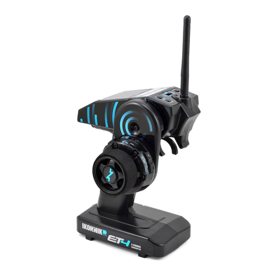
2.4GHz Radio System Features Please read and understand the following instructions for your new radio system prior to operation to ensure a safe and most enjoyable experience. For right-handed users, the transmitter should be held in the left hand with the wheel controlled by the right hand. - Page 7 1. Antenna: Transmits signal to the receiver located in the vehicle. Flip up when transmitter in use. Fold for storage. 2. Multifunction Red Indicator LED: a. Power indicator. b. Low battery voltage warning, batteries should be replaced/recharged before continued use when flashing. c.
-
Page 8: Receiver Installation And Connection
2.4GHz Radio System Receiver Installation and Connection Installation To achieve full operating range with your radio system, it is critical that the receiver antenna be installed properly and undamaged. It should be installed with as much of the antenna as possible in a vertical position. The end of the antenna should be contained inside an antenna tube. -
Page 9: Pairing The Transmitter And Receiver
Pairing the Transmitter and Receiver The process of allowing communication to occur between a 2.4GHz transmitter and receiver is called “pairing” (sometimes referred to as “matching” or “binding”). The radio system comes pre-configured and paired from the factory. In the event your system loses pairing, or one of the components has been replaced, you will need to pair the transmitter and receiver. -
Page 10: Digital Trim Settings
2.4GHz Radio System Steering Reverse REV/Pair button 1. Turn the steering wheel completely to the left (or right) and press the “REV” button for at least 3 seconds to reverse channel 1. 2. The transmitter will beep once for confirmation of “Normal” and twice for confirmation of “Reverse”... -
Page 11: Steering Dual-Rate (St D/R)
Throttle and Brake EPA Throttle CAUTION: FOR FUEL POWERED VEHICLES, PERFORM THIS STEP WITH THE ENGINE EPA buttons OFF, PRIOR TO CALIBRATE THE SERVO TRAVEL FOR THE CARBUREATOR. FOR ELECTRIC POWERED VEHICLES, PERFORM THIS STEP WITH THE VEHICLE OFF, PRIOR TO CALIBRATING THE ESC TO THE TRANSMITTER. Throttle Adjustment: Pull the throttle trigger completely to full throttle and use the “TH+”... -
Page 12: Beginner Mode And Feature Lock
Your IKONNIK transmitter is equipped with two proprietary features to improve and safeguard your experience with radio controlled products. Uniquely implemented by IKONNIK are both a Beginner Mode and Feature Lock. To avoid accidental changing of radio settings by inexperienced or younger users, you can set the mode switch to the middle position which will lock out all functions except the steering trim. -
Page 13: 10 Model Memory With Pair Safe Technology
10 Model Memory with Pair Safe Technology Your transmitter can store up to 10 models in memory, where all of the settings are stored independently for each model. This enables you to use one transmitter with up to 10 different vehicles. Incorporating Pair Safe technology ensures the transmitter will only control the receiver that is paired to the currently selected model. -
Page 14: Memory Reset
2.4GHz Radio System Memory Reset The transmitter has two memory reset features. The first is an individual model reset which as it might sound, resets most parameters to their factory default settings without affecting other models in memory. The second is a full factory reset which restores all parameters to their factory default settings and removes all paired receivers from memory. - Page 15 WARNING: DO NOT ATTEMPT TO CHARGE NON-RECHARGABLE BATTERIES, YOU MAY CAUSE AN EXPLOSION 1. Remove the battery cover from the transmitter. Safety Lock Battery Location 2. Remove the old batteries. 3. Insert the four new AA batteries according to the polarity markings on the battery holder.
-
Page 16: Calibrating Escs
2.4GHz Radio System Calibrating ESCs When calibrating your ESC and transmitter, ensure your Throttle Trim is centered and your Throttle and Brake EPA settings are set to their maximum of 100%. This will ensure your ESC reaches full throttle/brake when your trigger reaches full travel. -
Page 17: Using Your Transmitter For The First Time
Using Your Transmitter For The First Time WARNING: PERFORM THESE STEPS IN A SAFE ENVIRONMENT! MANY FIRST TIME USERS THINK THE STREET IS A GOOD PLACE TO TEST OPERATION, HOWEVER THIS IS DANGEROUS! WE RECOMMEND USING AN OPEN FIELD OR CLOSED AREA WITHOUT VEHICLE TRAFFIC Power 1. -
Page 18: Maintenance
2.4GHz Radio System Maintenance We want you to enjoy your product to its fullest potential. For this to happen it is important to keep your product clean and properly maintained. Lack of cleaning and maintenance can cause component failure. For best and continued performance from your product it is recommended to briefly inspect your product for damage every few uses. -
Page 19: Storage And Disposal
Storage and Disposal Storage • Always store all equipment in a cool dry place when not in use. • Always disconnect the batteries before storage. • Never store the transmitter or receiver in direct sunlight for extended periods of time. •... -
Page 20: Appendix
2.4GHz Radio System Appendix A: Grip Inserts The ET4 grip was engineered specifically to fit a wide range of users with varying hand sizes. Changing the grip size on your transmitter is easy and will allow for a safer, more comfortable and enjoyable user experience. For extra small hands, the transmitter can be operated without a rubber grip insert installed. - Page 21 Appendix B: Changing from Right- to Left-hand Configuration The ET4 wheel module was engineered to be versatile and accommodate a wide range of users. With the included components you have the option to position the wheel module in many positions to best suit your own ergonomics.
- Page 22 2.4GHz Radio System Tip: When reinstalling the wheel module, ensure the center of the wheel module is angled close to vertical, tilted slightly back towards the grip. This provides the most natural neutral position for the most common cant. 1. Remove the two screws on each side of the wheel module using a 2mm hex wrench.
- Page 23 11. Position the wheel module in place with vertical orientation properly set. 12. Reinstall 2 wheel module screws. Appendix C: Spare Parts List KNNS0001 ..ET4 4Ch 2.4GHz Xenon (Xe) AW Radio System KNNS0002 ..ET4 4Ch 2.4GHz Xenon (Xe) Transmitter KNNS0008 ..4Ch 2.4GHz Xenon (Xe) Receiver, AW KNNS0012 ..Battery Holder, 4xAA...
- Page 24 This warranty does not cover breakage due to abuse, improper break-in, improper setup, or improper operation. We at IKONNIK RC have made every effort in component design, material selection and assembly to make our products as durable as possible.
- Page 26 Scan this QR code with your smartphone for more information on the IKONNIK ET4. www.IKONNIK-RC.com 000554-002 (REV A)
Need help?
Do you have a question about the ET4 and is the answer not in the manual?
Questions and answers