Advertisement
Quick Links
Advertisement

Subscribe to Our Youtube Channel
Related Manuals for Insportline AX1001


Summary of Contents for Insportline AX1001
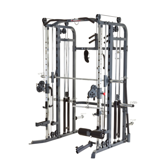
- Page 1 HOME FITNESS GYM AX1001 ASSEMBLY INSTRUCTIONS...
- Page 2 EXPLODED DIAGRAM...
-
Page 3: Part List
PART LIST NUMBER DESCRIPTION QUANTITY LEFT BASE RIGHT BASE LEFT MAIN UPRIGHT RIGHT MAIN UPRIGHT REAR LEFT UPRIGHT REAR RIGHT UPRIGHT LEFT SLIDE FRAME RIGHT SLIDE FRAME GUIDE ROD SHORT GUIDE ROD PLATE SUPPORT TOP FRAME BOTTOM CROSS FRAME MIDDLE CROSS FRAME TOP CROSS FRAME WEIGHT BAR PULL BAR... - Page 4 REINFORCEMENT PLATE REINFORCEMENT PLATE M10 BOLT CAP ROUND PLUG RUBBER CIRCLE RUBBER BUMPER SPIRNG CLIP-REGULAR SPIRNG CLIP-OLYMPIC LOCK PIN BEARING CIRCLE FOR HOLE PULLEY LARGE PULLEY NYLON BUSHING CLIP CABLE PLUM SHAPED SCREW SLIDER PIN M8*8 SOCKET SCREW M10*16 SOCKET CAP SCREW M10*25 SOCKET CAP SCREW M10*30 HEXAGONAL HEAD SCREW M10*50 SOCKET CAP SCREW...
-
Page 5: M10 Lock Nut
STEP 01 1.Attach the right main upright (4) and reinforcement plate (43) to the right base (2) using two M10*75 screws (66), four 10mm washers (69) and two M10 lock nuts (72). 2.Attach the rear right upright (6) and reinforcement plate (43) to the right base (2) using two M10*75 screws (66), four 10mm washers (69) and two M10 lock nuts (72). -
Page 6: Hook
STEP 02 1. Attach the bottom cross frame (13) and reinforcement plate (42) to rear left and right upright (5、 6) using four M10*70 screws (65), four M10*75 screws (66), sixteen 10mm washers (69) and eight M10 lock nuts (72). 2. -
Page 7: Guide Rod
STEP 03 1. Slide the left and right hook (28、29) onto the weight bar (16). 2. Slide the slide support (27) onto the weight bar (16). 3. Insert the short guide rod (10) into hole of the slide support (27) and rubber bumper (47), attach the short guide rod (10) to the left and right main upright (3、4) and the top frame (12) using four M10*70 screws (65) and four 10mm washers (69). -
Page 8: Plate Support
STEP 04 1. Attach the bar holder (30) to rear left upright (5) using two M10*30 screws (63) and two 10mm washers (69). Push the M10 bolt cap (44) onto screws (63). 2. Slide rubber bumper (47) and the plate support (11) onto the guide rod (9). Insert the guide rod (9) into hole of the left and right base (1、... -
Page 9: Nylon Bushing
STEP 05 1. Attach the rotation support (37) and nylon bushing (55) to main upright (3、4) or slide frame (7、8) use axis (39). Then lock with lock pin (50). 2. Attach the bar support (38) to the rotation support (37) using M12*105 screw (68), two 12mm washers (70) and M12 lock nut (73). - Page 10 STEP 06 Bring the threaded end of the cable (57) from A→B→C→D→E→F→G→H→24. NOTE: From F→G, the cable is IN the tube. Repeat the steps to route the cable through the right tower. Attach the pull bar (17) to cables (57) with clip (56).
- Page 11 HOME FITNESS GYM WITH PLASTIC WEIGHTS...
-
Page 12: M10*25 Socket Cap Screw
PART LIST NUMBER DESCRIPTION QUANTITY M10*25 SOCKET CAP SCREW 10MM WASHER SELECTOR SHARFT PLASTIC WEIGHT PLATE TOP PLATE SIDE SHELL LARGE WASHER PLASTIC CIRCLE SELECTOR PIN... - Page 13 1. If you want to use the plastic weight system, the assembly steps is the same as the bell piece system (STEP 01-06). But it is different on STEP 04. 2. Attach the side shell (78) to left and right main upright (3、4) using four M10*25 screws (62) and four 10mm washers (69).
- Page 14 EXERCISES START FINISH START FINISH...
- Page 15 START FINISH START FINISH...
- Page 16 START FINISH START FINISH...
- Page 17 START FINISH START FINISH...
Need help?
Do you have a question about the AX1001 and is the answer not in the manual?
Questions and answers