Advertisement
Quick Links
FOR SERVICE PERSONNEL ONLY
HITACHI
INVERTER SYSTEM MULTI TYPE
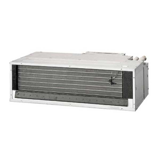
INDOOR UNIT
INSTALLATION MANUAL
RAD-18QPB
RAD-25QPB
MODEL
RAD-35QPB
RAD-50QPB
SAFETY PRECAUTION
l
Read the safety precautions carefully before operating the unit.
l
The contents of this section are vital to ensure safety. Please pay special attention to the following sign.
!
WARNING ........ Incorrect methods of installation may cause death or serious injury.
!
CAUTION ......... Improper installation may result in serious consequence.
Make sure to connect earth wire.
This sign in the fi gures indicates prohibition.
Be sure that the unit operates in proper condition after installation. Explain to customer the proper way of operating
the unit as described in the user's guide.
l
Please request your sales agent or qualifi ed technician to install your unit. Water leakage, short circuit or fi re may occur if
you do the installation work yourself.
l
Please observe the instructions stated in the installation manual during the process of installation. Improper installation may
cause water leakage, electric shock and fi re.
l
Make sure that the units are mounted at locations which are able to provide full support to the weight of the units. If not,
the units may collapse and impose danger.
l
Observe the rules and regulations of the electrical installation and the methods described in the installation manual when
dealing with the electrical work. Use wire which is approved offi cial in your country. A short circuit and fi re may occur due
to the use of low quality wire or improper work.
l
Be sure to use the specifi ed wire for connecting the indoor and outdoor units. Please ensure that the connections are tight
after the conductors of the wire are inserted into the terminals. Improper insertion and loose contact may cause over-heating
and fi re.
l
Please use the specifi ed components for installation work. Otherwise, the units may collapse or water leakage, electric shock
and fi re may occur.
l
When installing or transferring an air conditioner to another location, make sure that air other than the specifi ed refrigerant
(R410A) does not enter the refrigeration cycle. If other air should enter, the pressure level of the refrigeration cycle may
increase abnormally high leading to possibility of unit rupture.
l
Be sure to use the specifi ed piping set for R410A. Otherwise, this may result in broken copper pipes or faults.
l
When installing or removing an air conditioner, do not allow air or moisture to remain in the refrigeration cycle. Otherwise,
pressure in the refrigeration cycle may become abnormally high so that a rupture may be caused.
l
Be sure to ventilate fully if a refrigerant gas leak while at work. If the refrigerant gas comes into contact with fi re, a poisonous
gas may occur.
l
After completion of installation work, check to make sure that there is no refrigeration gas leakage. If the refrigerant gas
leaks into the room, coming into contact with fi re in the fan-driven heater, space heater, etc., a poisonous gas may occur.
l
Unauthorized modifi cations to the air conditioner may be dangerous. If a breakdown occurs please call a qualifi ed air
conditioner technician or electrician. Improper repairs may result in water leakage, electric shock and fi re, etc.
l
Be sure to connect the earth wire from the power supply wire to the outdoor unit and between the outdoor and indoor
unit. Improper earthing may cause electric shock.
l
A circuit breaker must be installed in the house distribution box for the direct connected power supply wire to the outdoor
unit. In case of other installations a main switch with a contact gap or more than 3mm has to be installed. Without a circuit
breaker, the danger of electric shock exists.
l
Do not install the unit near a location where there is fl ammable gas. The outdoor unit may catch fi re if fl ammable
gas leaks around it. Piping shall be suitable supported with a maximum spacing of 1m between the supports.
l
Please ensure smooth fl ow of water when installing the drain hose.
l
An IEC approved power cord should be used. Power cord type: NYM.
THE CHOICE OF MOUNTING SITE
(Please note the following matters and obtain permission from
customer before installation.)
!
WARNING
l
The unit should be mounted at stable, non-vibratory
location which can provide full support to the unit.
!
WARNING
l
No nearby heat source and no obstruction near the air
outlet is allowed.
l
The clearance distances from top, right and left are
specifi ed in fi gure below.
l
The location must be convenient for water drainage and
pipe connection with the outdoor unit.
l
To avoid interference from noise, please place the unit
and its remote controller at least 1m from the radio and
television.
l
To avoid any error in signal transmission from the remote
controller, please put the controller far away from high-
frequency machines and high-power wireless systems.
[Indoor unit installation]
Be sure to completely
seal any gap with putty.
l
The connecting pipe,
irrespective of the size,
should all be insulated
with insulation pipe and
then wrapped with vinyl
tape. (The insulator will
deteriorate if it is not
wrapped with tape).
Drain pipe
Must be installed separately.
Insulate indoor part of pipe to
prevent condensation.
l
"Height difference" and "Piping length" of Indoor and Outdoor unit are different by Outdoor unit.
Please refer to the installation manual in Outdoor unit.
<IA1171: A >
INS RAD-18-25-35-50QPB (EN) 1
INS RAD-18-25-35-50QPB (EN) 1
l
Carefully read through the procedure before start-
ing installation work.
l
The sales agent should inform customers regarding
the correct operation of installation.
l
Explanation for outdoor unit is in "How To Use"
(Instruction Manual) that is packed with outdoor unit.
Tools Needed For Installation Work
(Mark
is exclusive use tool for R410A)
l
+ – Screwdriver
l
Measuring Tape
l
Saw
l
ø 65mm Power Drill
l
Hexagonal Wrench
Key (
4mm)
l
Wrench (14, 17, 22, 26mm)
Leakage Detector
l
Pipe Cutter
l
Putty
l
Pliers
l
Flare Tool
Vacuum Pump Adapter
Manifold Valve
Charge Hose
!
WARNING
!
CAUTION
Accessories to indoor Unit:
No.
Item
1
Flare Insulator
Binder
2
3
4.0 x 10 Screw
4
Insulation Pipe
5
Aluminium Tape (large)
6
Band
7
Suspension Clamp (right, left) each
8
4.0 x 10 Screw
Other optional parts for display panel wired remote controller
& wireless remote controller SPX-RCDA & SPX-RCKA1
No.
Item
Display panel
1
Panel installation plate
2
Panel cover
3
Remote controller (wireless)
4
Remote Controller Holder
5
3.1 x 16 screw
6
Wired Remote Controller with 2 screws
7
!
CAUTION
Always install the indoor unit at level. If the
indoor unit is inclined, water may leak.
Air outlet
Filter
Air inlet
The indoor piping should
b e i n s u l a t e d w i t h t h e
enclosed insulation pipe. (If
the insulator is insuffi cient,
please use commercial
products.)
1. RECOMMENDATION FOR INSTALLATION
l
The fi gures below are the recommended installation type for this duct model.
l
All the optional parts mentioned for each installation type and screws should be purchased locally prior to the installation.
Full duct type
l
Knife
Gas
l
Vinyl Tape
Vacuum Pump
Need optional parts
when installing full duct type (Local purchase)
1
Discharge grille
Chamber of discharge grille ø150mm
2
3
Chamber of discharge of unit side ø150mm
4
Chamber of suction of unit side ø150mm
5
Chamber of suction grille ø150mm
Suction grille with fi lter
6
Flexible duct ø150mm 1m
7
Flexible duct ø150mm 2m
2. Installation procedure and notice
Select the installation location carefully for the split type
air conditioner. It is very diffi cult to move a split type air
conditioner after the fi rst installation.
2.1
Make a hole on the wall as shown in Fig. 2-1.
2.2 Connecting pipe installation
l
Seal the end of the pipes to prevent damage from
moisture and water.
GAS
Quantity
1
2
2.3 Drain pipe installation
2
l
Use PVC pipe VP20 (O.D. 25mm) for drain pipe.
l
You must roll an insulation (thickness 10mm or more) over the indoor section of the drain pipe.
1
l
Position the drain pipe in the downward direction to enable free-fl ow of water. Fix it with a hanger and avoid twisting the pipe as
1
shown in Fig. 2-3.
1
2
Downward 1/25 ~ 1/100
8
Quantity
Insulation
1
(Thickness 10mm or more)
1
1
1
1
2.4 Installation method of unit type
2
1
INSTALLATION OF FULL DUCT TYPE
Electrical
box
l
Permissible length and bending of duct.
Wired
Discharging side duct
remote
controller
Suction side duct
l
Secure the space for installation, inspection or servicing.
l
Apply water-proof treatment to back surface of ceiling under the indoor unit, to prevent water drop.
l
Do not allow any obstacle to block air fl ow within 1m of suction grille.
Semi duct type
Need optional parts
when installing semi duct type (Local purchase)
1
Discharge grille
2
Chamber of discharge grille ø150mm
3
Chamber of discharge of unit side ø150mm
4
Suction grille
Flexible duct ø150mm 1m
5
Flexible duct ø150mm 2m
Non duct type
Need optional parts
when installing non duct type (Local purchase)
1
Discharge grille
2
Discharge duct
3
Suction grille
2 ~ 5mm
Indoor
Outdoor
side
side
Fig. 2-1
Large diameter pipe
Small diameter pipe
„
Insulation pipe
Fig. 2-2
Seal
No trap
Do not do the installation as shown as above
Fig. 2-3
l
Select the indoor unit position, fi xing direction of air outlet so
that cool/hot air reaches all the room. Standard position of
the indoor unit is with the wall side on the ceiling.
l
Remove the factory fi tted fi lter and fi lter holders before installing
of full duct type.
Permissible length
4m or less added to suction side
90° or less, 1 section
1m or less
45° or less, 1 section
l
The hole on the wall
should be made
with some inclination
like Fig. 2-1 to keep
the smooth fl ow of
65mm
condensed water.
Tape
(Unit : mm)
No insulation
Stagnant water
Bending
12/19/14 9:42 AM
12/19/14 9:42 AM
Advertisement

Related Manuals for Hitachi RAD-18QPB


Summary of Contents for Hitachi RAD-18QPB
-
Page 1: Safety Precaution
Tools Needed For Installation Work INSTALLATION MANUAL (Mark is exclusive use tool for R410A) + – Screwdriver Measuring Tape Knife ø 65mm Power Drill Hexagonal Wrench RAD-18QPB Key ( 4mm) Wrench (14, 17, 22, 26mm) RAD-25QPB MODEL Leakage Detector Pipe Cutter Putty... - Page 2 (1) Installation fi gure Remove the screw Indoor unit Discharge opening size Top plate Opening on ceiling 233 (Unit : mm) Opening on ceiling 96 Suction opening size (846 x 96) Suspension bolt 347 (960 x 233) Screws to fit electric box Flexible duct Flexible duct...
- Page 3 • Chamber of discharge grille (3) Installation of suspension bolt • This is the same as for discharge/suction duct type. Suspension bolt (M10: Local purchase) Follow instructions for discharge/suction duct type. Reinforcement ‡ Left side ‡ Right side suspension clamp (2) (4) Preparation for installing indoor unit suspension clamp (2) ƒ...
- Page 4 2.7 Pipe connection Wiring installation illustrations CAUTION Inside top wiring installation (Alternative) Wall recessed wiring installation (Optional) In case of removing flare nut of an indoor unit, first remove a nut of small diameter side, or a seal cap of big diameter side will fly out.