Sign In
Upload
Manuals
Brands
York Manuals
Air Conditioner
eco2 065
York eco2 065 Manuals
Manuals and User Guides for York eco2 065. We have
2
York eco2 065 manuals available for free PDF download: Installation Operation & Maintenance, User Manual
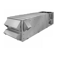
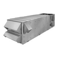
York eco2 065 Installation Operation & Maintenance (176 pages)
PACKAGED ROOFTOP AIR CONDITIONING UNITS
Brand:
York
| Category:
Air Conditioner
| Size: 2.42 MB
Table of Contents
Nomenclature
3
Table of Contents
4
Section 1 Introduction
8
Ecological & Economical Design
8
Indoor Air Quality
8
Fig. 1 - Packaged Rooftop Air con DI Tion Ing Unit
8
Reliable Scroll Compressor Technology
9
Serviceability
9
Install with Ease and Safety
9
Section 2 Installation
11
Approvals
11
Limitations
11
Unit Inspection
11
Location and Clearances
11
Table 1 - Voltage Limitations
11
Rigging and Handling
12
Fig. 2 - Unit Rigging
12
Fig. 3 - Unit Clearances
12
Physical Data
13
Table 2 - Physical Data
13
Table 3 - Electrical Data
21
Airß Ow and Entering Air/Ambient Limitations
23
Table 4 - Air Flow & Entering Amb. Limitations
23
Filters
24
Condensate Drain
24
Fig. 5 - Trap Detail-Draw through Application
24
Air Hoods for Economizer
25
Air Hoods for Fixed Outside Air (Units Without Economizer)
25
Air Hoods for Exhaust Air
25
Field Wiring
25
Evaporator Coil Face Damper
26
Return Air Bypass Damper
26
Roof Link
27
Bacnet and Lon Network Communication
27
Dirty Filter Switch
27
Fig. 6 - Network Communication Board
27
Fig. 7 - Field Control Wiring
28
Ctb2
29
Fig. 8 - Flexsys CTB2 Wiring
29
Power Wiring
30
Electrical Service Sizing
30
Single-Point Power Supply Wiring
31
Fig. 9 - Single-Point Power Supply Wiring
31
Single-Point Power Supply Wiring with Non-Fused Disconnect Switch
32
Dual-Point Power Supply Wiring
33
Fig. 11 - Dual-Point Power Supply Wiring
33
Roof Curb Installation
34
Duct System
34
Sound and Vibration Transmission
35
Fig. 12 - Static Pressure Probe Location
35
Section 3 Start-Up
36
Crankcase Heaters
36
Checking the System Prior to Initial Start (no Power)
36
Unit Checks (Power Applied)
37
Fig. 13 - Supply Fan Isolator Spring Bolts
37
Initial Start-Up
38
Table 5 - R-22 Temperature/Pressure Chart
39
Table 6 - 407C Temperature/Pressure Chart
40
Gas Heat Models
41
Table 7 - Gas Heat Performance Data
42
Section 4 Maintenance
44
General
44
Periodic Maintenance - Monthly
44
Table 8 - Fan Bearing Lubrication Intervals
44
Periodic Maintenance - Three to Six Months
45
Periodic Maintenance - Yearly
45
Fig. 14 - Sheave Alignment
45
Fig. 15 - Fan Data Plate - Belt Tension
46
Fig. 16 - Belt Tensioning Gauge
46
Fig. 17 - Example of FC Fan Shaft/Wheel Marking
47
Fig. 18 - Bearing with Setscrew Type Locking
49
Fig. 19 - Bearing with Eccentric Cam
49
Table 9 - Set Screw Torque
50
Fig. 21 - Split Bearing
50
Fig. 20 - Eccentric Cam Locking Collar
50
Section 5 Unit Sequence of Operation
51
Compressor Staging
51
Compressor Average Run Times
52
Supply Fan Operation
52
Timeouts and Delays
53
Constant Volume Sequence of Operation
53
Table 14 - Timeouts and Delays
53
Table 15 - Staged Heating Steps
54
Fig. 22 - CV Space Sensor Cooling al Go Rithm
55
- Econ O Miz er Not Suitable
55
Fig. 23 - CV Space Sensor Cooling Algorithm
55
Fig. 24 - CV Space Sensor Stepped Heat Algorithm
56
Table 16 - Modes of Operation
57
Variable Air Volume Sequence of Operation
58
Fig. 26 - VAV Occupied Heating to Maintain RAT
59
Morning Warm up
59
Fig. 28 - VAV Unoccupied Cooling Tem Per a Ture
60
Fig. 29 - Compressor Staging for VAV Cooling
60
Fig. 30 - Occupied Heating and Cooling Setpoint
61
Table 17 - VAV Modes of Operation
62
Economizer Operation
63
Ventilation Option Operation
64
Fig. 31 - OAD Minimum Position Reset
65
Area and K Factor
66
Table 18 - Area and K Factor
66
Fig. 32 - Minimum Flow Measurement
67
Fig. 33 - Control for Minimum AMS - Economizer
67
Fig. 34 - Minimum Flow Measurement Option, Economizer Sequence
68
Fig. 35 - Full Flow Measurement Arrangement
68
Fig. 36 - Full Flow Measurement Option, Economizer Not Avail Able
69
Fig. 37 - Full Flow Measurement Option Economizer
69
Low Ambient Operation
70
Fig. 38 - Low Ambient Hardware
71
Fig. 39 - Condensing Pressure Control Proportional
71
Controlling Excessive Supply Air Temperature Sat
72
Power Exhaust Operation
72
Fig. 40 - OAD Position Control
73
Fig. 41 - Building Pressure Control
73
Fig. 42 - Exhaust Proportional Band
74
Fig. 43 - Exhaust Fan Control, Pro por Tion al
74
Time Clock/Scheduling
75
Changeover Relay Operation
75
High Pressure Unloading
75
Comfort Ventilation Operation
75
Hot Water Freeze Protection Using RA Operation
76
Smoke Purge Operation
76
Return Fan Operation
77
Modulating Gas Heat
80
Fig. 44 - Modulating Gas Heat Staging
80
Compressor Operating Controls
81
Refrigerant Safety Operation
82
Flexsys VAV Operation
82
Fig. 45 - By-Pass Damper Formulas
83
Fig. 46 - Bypass Damper Setpoints
84
Section 6 Menu Navigation and Display Descriptions
85
Optilogic Control Center
85
Navigating the Menus
85
History Menu Navigation
85
Unit Status" Navigation
85
Operation Data" Navigation
89
Setpoints" Navigation
92
Unit Setup" Navigation
92
Conþ Guration" Navigation
94
Service" Navigation
95
History" Navigation
98
Table 19 - History Function Text
99
Table 20 - History Points Data List
99
Section 7 Parameter Descriptions and Options (Setpoints)
100
Parameter Description and Options (Setpoints)
100
Status Key Parameters
100
Setpoint Key Parameters
100
Fig. 47 - ODA Damper Position Vs. VAV Sup Ply Fan
101
Unit Setup Key Parameters
102
General Setup
102
Heat/Cool System
103
VAV System
104
Econo/Exhaust System
105
Ventilation
106
Warm-Up Purge
106
Conþ Guration Key Parameters
107
General
107
Run Test
107
Panel Test
108
Heat/Cool System
108
Excessive SAT
108
Econo/Exhaust Vent
109
Service Key Parameters
110
Changing Setpoints
110
Table 21 - Setpoints and Values
113
Fig. 48 - Primary Unit Controller
116
Fig. 49 - Primary Unit Controller Connection Map
117
Fig. 50 - Binary LED Designations
118
Binary Input Operation
119
Analog Input Operation
122
Table 22 - Temperature Sensor Resistance
122
Table 23 - Duct Pressure Transducer Output
122
Table 24 - Building Pressure Transducer Output
123
Table 25 - AMS Pressure Trans Duc er Output
123
Table 26 - Discharge Pressure Transducer Output
123
Table 11 - CV 4 or 6 Compressor Logic - Staging Table 27 - Suction Pressure Transducer Output
124
Table 28 - Monitor & Control I/O for Primary Unit Table 12 - VAV Four or Six Compressor Logic - Controller
125
Control
125
Fig. 51 - MOD-UNT
125
Fig. 52 - MOD-UNT Wiring Diagram
125
Table 29 - Humidity Sensor Output
126
Table 13 - VAV Four or Six Compressor Logic - Table 30 - CO2 Sensor Output
126
Table 31 - T'stat Interface Board Voltage Outputs
127
Output
127
Table 32 - T'stat Interface Board Connections
128
Fig. 53 - Thermostat Interface Board
128
Table 33 - Input/Output Table
129
Service
130
Fault Descriptions
131
Table 34 - Fault Description Table
132
Wiring Diagrams
136
Advertisement
York eco2 065 User Manual (76 pages)
eco2 Packaged Rooftop Air Conditioning Units, 50 THROUGH 100 TONS R-407C and R-22 400VAC/3PH/50Hz
Brand:
York
| Category:
Air Conditioner
| Size: 0.54 MB
Table of Contents
Introduction
2
Table of Contents
3
Features and Benefits
4
Nomenclature
7
Application Data
8
Physical Data
12
TABLES Physical Data
12
Cooling Performance Data
16
Cooling Performance Data - 50 Ton Model
16
Cooling Performance Data - 55 Ton Model
18
Cooling Performance Data - 60 Ton Model
20
Cooling Performance Data - 65 Ton Model
22
Cooling Performance Data - 70 Ton Model
24
Cooling Performance Data - 75 Ton Model
26
Cooling Performance Data - 80 Ton Model
28
Cooling Performance Data - 85 Ton Model
30
Cooling Performance Data - 90 Ton Model
32
Cooling Performance Data - 95 Ton Model
34
Heating Performance Data - Gas/Electric Heat
36
Gas Heat Performance Data
36
Electric Heat Performance Data
36
Supply Fan Data
37
50 Through 65 Ton Supply Fan Data
37
70 Through 85 Ton Supply Fan Data
38
90 Through 95 Ton Supply Fan Data
39
Component Static Pressure Drops
40
Gas Heat Pressure Drops
44
Electric Heat Pressure Drops
46
Exhaust Fan Data
48
60 Through 65 Ton Exhaust Fan Data
48
70 Through 85 Ton Exhaust Fan Data
49
90 Through 95 Ton Exhaust Fan Data
49
Component Static Pressure Drops
50
Electrical Data
52
Compressor Data
52
Supply and Exhaust Fan Motor
53
Condenser Fan Motors
53
Control Transformer
53
Electric Heat
53
Controls
54
Power Wiring
60
Single-Point Power Supply Wiring
60
Single-Point Power Supply Wiring with Non-Fused Disconnect
61
Dual-Point Power Supply Wiring
62
Field Control Wiring
63
General Arrangement Drawings
64
General Arrangement - 50-65 Ton Models (Bottom Supply/Bottom Return)
64
Gen. Agmt. Dwg. - 50-65 Ton Models (Bottom Supply/Bottom Return)
64
General Arrangement - 50-65 Ton Models (Side Supply/Front Return)
65
Gen. Agmt. Dwg. - 50-65 Ton Models (Side Supply/Front Return)
65
General Arrangement Drawing
66
General Arrangement - 70-95 Ton Models (Bottom Supply/Bottom Return)
66
Gen. Agmt. Dwg. - 70-95 Ton Models (Bottom Supply/Bottom Return)
66
General Arrangement - 70-95 Ton Models (Side Supply/Front Return)
67
Gen. Agmt. Dwg. - 70-95 Ton Models (Side Supply/Front Return)
67
General Arrangement - 70-95 Ton Optional Side Return
68
Gen. Agmt. Dwg. - 70-95 Ton Models (Optional Side Return)
68
Curb Layout Drawing
69
Curb Layout Dimensions
69
Power/Control Entry Drawing
70
Power/Control Dimensions
70
Power/Control Entry Drawing - 50-95 Ton Model
70
Guide Specifications
71
Advertisement
Related Products
York ECO2 YPAL 050
York eco2 055
York eco2 070
York eco2 075
York eco2 080
York eco2 085
York eco2 090
York eco2 095
York Eco 2
York eco2 105
York Categories
Air Conditioner
Heat Pump
Chiller
Furnace
Air Handlers
More York Manuals
Login
Sign In
OR
Sign in with Facebook
Sign in with Google
Upload manual
Upload from disk
Upload from URL